RedEarth BlackMax User manual

BlackMax – Installation Manual
RE_PROD_0005 Version 4 Page 1 of 32 Issue Date 23/03/2021
BlackMax
Off-Grid Battery System
Installation Manual

BlackMax – Installation Manual
RE_PROD_0005 Version 4 Page 3 of 32 Issue Date 23/03/2021
WARNING: Working on the inside of the BlackMax system is restricted to qualified personnel.
RedEarth recommend installation by licensed electricians only.
WARNING: Lithium Battery hazard
The BlackMax must only be installed by suitably qualified personnel who have read
and are familiar with its operation and hazards.
This manual covers all following model numbers: BMX-104, BMX-108, BMX-112,
BMX-203, BMX-207,
Safety
CAUTION: The battery provided with this system must be charged only by the
ShurePower inverter Do not attempt to charge the batteries with any other charger
device or connect any devices directly to the DC battery bus.
Attempt to do so will void warranty.
The wiring diagrams and installation instructions are given as a guide only and
compliance to appropriate standards is the responsibility of the installer. Relevant
standards are listed below:
AS/NZS 3000:2018
Wiring rules
AS/NZS 5033:2014 (amdt 1&2)
Installation and safety requirements for
photovoltaic (PV) arrays
AS/NZS 4509.2:2012
Stand-alone power systems-Design
AS/NZS 1170.2:2011
Structural design actions-Wind actions
AS/NZS1768:2007
Lightning protection
AS/NZS 3008.1.1:2017
Electrical installations – Selection of cables
AS/NZS 5139:2019
Electrical installations-Safety of battery
systems for use with power conversion
equipment
Fire
In the advent of fire evacuate the area and call emergency services. A dry agent fire extinguisher should
be readily available and used. DO NOT use water. Evacuate the area and call emergency services. Toxic
gas may be produced if the battery catches fire.
Note: SDS document is provided with the system and also can be found at www.redearth.energy
Damaged battery
Do not use a damaged battery. Batteries should only be disposed of at an appropriate recycling centre.
Please contact RedEarth for advice.
In our efforts towards constant product enhancement, this document is subject to
change at any time. Please visit www.redearth.energy
and download the
appropriate and latest version manual.

BlackMax – Installation Manual
RE_PROD_0005 Version 4 Page 4 of 32 Issue Date 23/03/2021
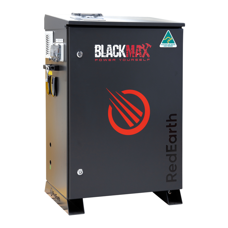
RedEarth’s BlackMax battery system is a ready-to-run energy storage system for off-grid
applications. It consists of a SurePower 5000 hybrid inverter and up to three (3) self-managed
lithium batteries (12.4kWh total). It is fully assembled, factory tested and requires no programming.
It is ready to connect a PV Solar array and a generator (either auto or manual start)
The BlackMax system is designed to be installed either inside or outside, ideally on a flat surface
and in a shaded area against a wall.
RedEarth Energy Storage can also provide an opptional remote monitoring service to ensure
ongoing operation of the BlackMax battery system.
A typical complete installation of the BlackMax with solar panels, will require the electrical connection
of:
•The customers load (via
external GPO) or harwiring to
a terminal block.
•The array of PV solar panels
– via MC4 conectors on the
inside of the unit.
•Generator (via external GPO)
or harwiring to a terminal
block.
Note: The BlackMax is not designed to act as a main switch board for the premises, as it does not
include space for additional main & customer circuit breakers or RCDs. The MEN link and Earth
connection need to be in place at the premises as required by national standards.
Overview:

BlackMax – Installation Manual
RE_PROD_0005 Version 4 Page 5 of 32 Issue Date 23/03/2021
BlackMax Weight: 176kg with 3x Troppo batteries (42kg per battery)
Or: 114kg with 2 Pylontech batteries (32kg per battery)
Dimensions w/ door and lid closed: 1028 H x 750 W x 475 D [mm]
Dimensions & Clearance
BlackMax Minimum Clearance
According to AS/NXS 5139
BlackMax Fully Open
1433 H x 750 W x 1106 D [mm]

BlackMax – Installation Manual
RE_PROD_0005 Version 4 Page 6 of 32 Issue Date 23/03/2021
Opening the BlackMax
RedEarth’s BlackMax energy storage system can
be accessed via the top (lid) or the front door.
To open the lid, 2 screws (one from each side)
must be removed and then the lid can be lifted and
pivoted on the rear hinge similar to “popping the
bonnet” of a car.
To access from the front, there are 2 locks that
must be operated on the front door. The key to
open these locks comes tied to the left handle and
must be kept out of the reach from children.
Inside
The BlackMax can be divided into four main areas, The AC side, the DC side, the inverter, and the
battery area. By opening the front door - as explained above – you will have access to the AC side,
inverter area, and DC side. To access the AC or DC side, you will have to remove the acrylic barrier
that is held in place by 3 nuts. Finally, to access the battery area, all you need to do is “pop the
bonnet”. This is procedure explained in “Opening
the BlackMax”.
Note: When closing, do not over tighten the
nuts holding the clear cover in place as it will
crack under pressure.
Components

BlackMax – Installation Manual
RE_PROD_0005 Version 4 Page 7 of 32 Issue Date 23/03/2021
The main components of the BlackMax are the hybrid inverter (SurePower 5000 by RedEarth), one,
two or three Lithium batteries and several other small devices that are shown in the picture below.
All electrical connections can be made via plugs, making the system user friendly and extremely
quick to install.
Earth Fault Alarms
RedEarth recommend using AERL EarthGuard for Earth Fault Alarms when available. Please
contact AERL https://www.aerl.com.au/ for details.
Components

BlackMax – Installation Manual
RE_PROD_0005 Version 4 Page 8 of 32 Issue Date 23/03/2021
Components

BlackMax – Installation Manual
RE_PROD_0005 Version 4 Page 9 of 32 Issue Date 23/03/2021
The BlackMax comes fully equipped with the following items.
•BlackMax pre-wired enclosure
•RedEarth - SurePower inverter
•Up to 3x Troppo Batteries
•Installation Manual
•User Manual
Many customers request the Solar Power Kit which is
shown at the left and can include:
•Pallet (1.6W 1.16D 0.15H [m])
•BlackMax (with 1 or 2 batteries)
•Solar Panels (between 8 and 16)
•Clenergy PV mounting hardware and rails for tin roof
(custom length)
•15A lead for generator
•Optional
oHonda EU22i (registered in the customer’s name)
oHand trolley to help with the transporting the BlackMax
Components
Kit Dimensions:
1.6 W 1.116 H 1.14 D [m]
360 ~ 530kg

BlackMax – Installation Manual
RE_PROD_0005 Version 4 Page 10 of 32 Issue Date 23/03/2021
7 steps to complete your BlackMax installation:
1. Transporting
2. Positioning
3. Solar Install
4. Electrical connections
4.1. Solar
4.2. Battery
4.3. Load
4.4. Generator
4.5. Generator Auto-Start
4.6. MSB
4.7. Monitoring
5. Turn ON/Commissioning
5.1. Turn ON
5.2. Shutdown
5.3. Commissioning
5.4. Fan Control Adjustment
6. Monitoring and Communication
7. Finalizing and Handover
Step 1. Transporting
The BlackMax system is supplied on a pallet in one
of two configurations (just unit or kit) as shown on
right. It is fully set-up and ready to run. The system
weighs around 176kg with 3x lithium batteries and
should be handled with proper lifting equipment.
RedEarth’s BlackMax
comes fitted with two
handles to help with
handling. However, it is a heavy unit and should be managed with a
transportation device such as a hand trolley. This is available as an
option from RedEarth.
As a last resort, the lithium batteries can be removed and replaced once
the system is in position. Each Troppo battery module weighs 42kg and
should be lifted with the extreme caution.
Installation

BlackMax – Installation Manual
RE_PROD_0005 Version 4 Page 11 of 32 Issue Date 23/03/2021
Step 2. Positioning
The BlackMax is designed to be a freestanding
weatherproof system (suitable for wet locations).
However, we strongly recommend it to be placed close
(300mm) to a wall in a shaded area to reduce the chances
of overheating. It should also be placed as close as
possible to the solar panels and MSB to minimise voltage
drop/power loss (<10m).
Cooling air flow passes up through the base of the system
and then out the top left-hand side.
Do not block the air vents otherwise the system will
overheat and shutdown. Once the system cools down
again it can be restarted. The flow of air is assisted by an
electric fan connected to one of the rear vents. It is
controlled by an adjustable temperature switch set to
30⁰C in the factory.
•Allow 60cm spacing on both sides of the system.
With the help of a hand trolley, you can roll the system into
place and secure it to the floor.
The BlackMax has four holes in the base to allow for
securing. This can be done with dynabolts or material
appropriate screws.
Step 3. Solar Install
The PV Array should be designed and installed in accordance with AS/NZS
5033 and the latest CEC Installation guidelines. Caution should be taken in
selecting PV panels and wiring method to ensure Open Circuit Voltage (VOC)
and Short Circuit Current (ISC) is not exceeded.
Installation
BlackMax Minimum Clearance
According to AS/NZS 5139
WARNING: The Solar DC Isolator on the BlackMax must be in the off position
before any solar panels are connected
PV array must be floating (must not be grounded)
Ensure that the array is within the inverter specification and polarity
of the array is correct.
PV modules must have an IEC61730 Class A rating

BlackMax – Installation Manual
RE_PROD_0005 Version 4 Page 12 of 32 Issue Date 23/03/2021
Step 4. Electrical connections
BlackMax is designed to be a plug and play unit. However, this limits the output to 15A
(approximately 3kW). To unleash the full power of the BlackMax, it must be hardwired to a remote
switchboard, which contains a MEN and earth stake. To do so, open up the unit as explained in
“Opening the BlackMax”, remove the clear cover on the AC side by undoing the 2 screws holding it
in place. This allows access to the terminal blocks, GPO’s, breakers, earth and neutral bars.
Earthing the Unit: The unit should be earthed to an appropriate earth stake. The earth cable can be
connected to the earth bar (or terminal block) inside the unit.
MEN Link: There is a MEN link installed in the BlackMax. If an external switchboard contains a MEN
link, then the one inside the BlackMax should be removed & the BlackMax hard wired to the main
switchboard.
4.1. Solar
For ease installation, the BlackMax comes with its own PV isolation device
and pre-terminated MC4 connectors on the inside of the unit.
To connect the solar power, insert the unterminated cables (coming from the
PV array) into the system and then terminate the correct MC4’s on the cables.
With the BlackMax PV isolator still in the off position, connect the PV cables
to the unit, check for correct polarity and VOC on the isolator terminals.
4.2. Battery
The batteries are shipped inside the unit and can be found in the rear section. For transportation or
maintenance purpose, the batteries can be accessed from the top by lifting the lid or the rear by
removing the back-plate.
Installation
Before any electrical connections are made, check all internal connections are secure and
have not come loose during transport.
Ensure that all breakers and isolators, as well as those supplying power to the unit, are
turned OFF.
Installing an PV array with voltage or current values above the inverter rating will damage the
BlackMax unit and will void warranty.
When exposed to light, photovoltaic (PV) array supplies D.C. voltage to the PCE

BlackMax – Installation Manual
RE_PROD_0005 Version 4 Page 13 of 32 Issue Date 23/03/2021
Removing or Installing a TROPPO:
To remove or install a battery, you will need to follow these steps:
•Remove the battery cables by pressing the button on the
side of the terminal and pull it straight up;
NOTE: When installing the battery cable, simply push it onto
the terminal until you hear a click.
•Remove the bolt that holds the earth cable to the battery;
•Remove the bolts the hold the back-plate in place;
•Remove the battery locating plates;
•Slide out one battery at a time. Be careful handling as each
battery weighs 42 kilograms.
To install a battery, follow this process in reverse.
ATTENTION: If the battery polarity is connected incorrectly it will damage the
BlackMax system.
Installation

BlackMax – Installation Manual
RE_PROD_0005 Version 4 Page 14 of 32 Issue Date 23/03/2021
Removing or Installing a US3000:
To remove or install a battery, you will need to follow these steps:
•Remove the battery cables by pressing the button on the
side of the terminal and pull it straight up;
NOTE: When installing the battery cable, simply push it onto
the terminal until you hear a click.
•Remove the CAT5 cables
•Remove the bolt that holds the earth cable to the battery;
•Remove the bolts the hold the lid down;
•Lift out one battery at a time. Be careful handling as each
battery weighs 32 kilograms.
To install a battery, follow this process in reverse.
ATTENTION: If the battery polarity is connected incorrectly it will damage the
BlackMax system.
Installation

BlackMax – Installation Manual
RE_PROD_0005 Version 4 Page 15 of 32 Issue Date 23/03/2021
4.3. Load
Power to the loads is supplied via the external Power Point or
by hardwired connection. If hardwiring, simply attach the Active,
neutral and earth to the terminals blocks labelled “Loads” on the
inside of the unit. Alternatively, plug in a device to the GPO
labelled Power Output.
Note that this output is limited to 15 Amps (approximately 3kW).
4.4. Generator Connection
Power to the BlackMax can be supplied via the external power
inlet or hardwire connection.
If connecting the generator via power inlet, simply attach the
device to the power inlet labelled “GENERATOR INPUT”.
NOTE: A 15A rated cable must be used for this input.
The following specifications must also be met for a guaranteed
compatibility with the inverter.
-Generator waveform THD: < 10%.
-Generator Vrms range: 180 ~ 264Vac
-Generator voltage crest factor (Vpeak/Vrms): < 1.6
-Generator peak voltage: <380V
-Frequency range: 45Hz ~ 55Hz
-Frequency slew rate: <0.3Hz/sec
To hardwire the generator, the leads from the Gen inlet must be
removed from the terminal block and terminated. Then secure
the active neutral and earth to the terminal blocks.
NOTE: If the system is hardwired, there are stickers in the parts
kit to be placed on the power inlet lead as well as the power inlet.
4.5. Generator Auto-Start
BlackMax contains three terminals (NO, C and NC) on the bottom of the display. These terminals
are connected to a dry contact that can be programmed to automatically start a generator, or it can
be used to activate a signal light indicating that the manual start generator is required. To learn how
to configure this relay, please refer to the SurePower Manual
Tip: When using an AutoStart generator, install a small battery charger on the generators battery
so it does not discharge over time.
Installation

BlackMax – Installation Manual
RE_PROD_0005 Version 4 Page 16 of 32 Issue Date 23/03/2021
4.6. MSB
If the BlackMax is hardwiried into a SwitchBoard, RedEarth recommends
it to be connected to an appropriately rated circuit breaker on the far left-
hand side as shown below.
Note: this Switchboard must contain all necessary stickers and traffolytes
i.e. PV and ES. These can be found in the Parts Kit Box.
Note:If required, SunRise is compatible with RCD type A and must be
triggered at a current of 300mA or higher
Step 5. Monitoring
There are currently two ways to install monitoring/communication.
•Display
•Remote Monitoring (Optional)
The first option does not require any installation as the display is already installed on the lid of the
unit. However, there is the option of relocating the display within 20 meters of the unit. In this case,
installation of a longer CAT5 cable is required (CAT5 cable not supplied).
The remote monitoring option uses a RedEarth hardware. Apart from positioning the antenna in a
good 4G reception area, this also does not require installation as it is done and tested in factory.
If purchased from factory, the BlackMax will come with a weatherproof gland in the parts kit box.
The antenna must pass through it and then the gland must be tightened on the unit.
The ideal positioning of the antenna is on top of the unit or somewhere with good mobile reception.
Once this is done as well as the start-up procedure, call RedEarth – Tech Support to confirm its
operation.
Installer login is available in addition to customer logins. Contact Tech support for information.
NOTE: This option must be requested as it is not part of the standard BlackMax
Installation

BlackMax – Installation Manual
RE_PROD_0005 Version 4 Page 17 of 32 Issue Date 23/03/2021
Step 6. Turn ON (Pylontech)
To turn on the unit you must follow the steps below:
1 Under the lid, switch ON the batteries and press the SW button on the master battery The
LED on each battery will come on.
2 Switch ON the BATTERY SYSTEM D.C. ISOLATOR (#4), found on the RHS of the unit;
3 Switch ON the SOLAR D.C. ISOLATOR (#3), found on the RHS of the unit;
4 Turn ON all AC circuit breakers (#2), found on the LHS of the unit;
5 Press the “On/Off” button (#1) on the display, found on the lid of the unit;
Powering ON Batteries
A. Switch on all the battery modules:
B. The one with empty Link Port 0 is the Master Battery Module, other is a slave
C. Press the red button of master battery to power on, all the battery LED light will be on one
by one from the Master battery
NOTE: For more information on this battery, see Manual – US3000 on RedEarth download page.
Use the table below to check correct operation of the battery.
1
2
3
4
5
Installation

BlackMax – Installation Manual
RE_PROD_0005 Version 4 Page 18 of 32 Issue Date 23/03/2021
Turn ON (Troppo)
To turn on the unit you must follow the steps below:
1 Under the lid, switch ON the battery breakers on the top of each Troppo battery. The LED
on each battery will come on.
2 Switch ON the BATTERY SYSTEM D.C. ISOLATOR (#4), found on the RHS of the unit;
3 Switch ON the SOLAR D.C. ISOLATOR (#3), found on the RHS of the unit;
4 Turn ON all AC circuit breakers (#2), found on the LHS of the unit;
5 Press the “On/Off” button (#1) on the display, found on the lid of the unit;
NOTE: The numbers on the equipment are in descending order. The ascending sequence is the
Shutdown procedure.
1
2
3
4
5
Installation

BlackMax – Installation Manual
RE_PROD_0005 Version 4 Page 19 of 32 Issue Date 23/03/2021
Step 7. Shutdown
The shutdown procedure is the reverse of the “turn on” procedure and is shown below. This
procedure can be found on the unit.
1 Press the “On/Off” button (#1) on the display, found on the lid of the unit;
2 Turn OFF all AC circuit breakers (#2), found on the LHS of the unit;
3 Switch OFF the SOLAR D.C. ISOLATOR (#3), found on the RHS of the unit;
4 Switch on the BATTERY SYSTEM D.C. ISOLATOR (#4), found on the RHS of the unit;
The battery breaker on top of each battery does not have to be turned off if the BATTERY SYSTEM
D.C.ISOLATOR is already off. However, we do recommend turning them off for long term storage
(up to 6 months).
After 6 months the system should be restarted to recharge the batteries (e.g. via the generator).
Installation

BlackMax – Installation Manual
RE_PROD_0005 Version 4 Page 20 of 32 Issue Date 23/03/2021
Step 8. Commissioning
The BlackMax is commissioned and tested in RedEarth’s factory to guarantee correct operation of
the system as ordered. However, last-minute parameter adjustments may be required (eg. generator
size/ charging rate or increasing energy storage). Carefully follow the procedure in the SurePower
Quick Start Guide on how to make these alterations without compromising the existing configuration.
NOTE: This must be done by a qualified person.
The original SurePower, display and battery manuals are included in the system. These may need
to be referred to for additional details required during setup and programming.
Fan Control Adjustment:
The thermostat is located inside the unit next to the GPO’s.
This automatically starts the fans once the temperature rises
above the set-point. This set-point can easily be adjusted with
a small screwdriver. It is set to 30⁰Celsius in the factory.
Installation
Other manuals for BlackMax
4
Table of contents
Other RedEarth Batteries Pack manuals

RedEarth
RedEarth DropBear User manual

RedEarth
RedEarth SunRise SRS-3 Series User manual

RedEarth
RedEarth HoneyBadger User manual

RedEarth
RedEarth BlackMax User manual

RedEarth
RedEarth SunRise SRS-3 Series User manual

RedEarth
RedEarth DropBear User manual

RedEarth
RedEarth BlackMax User manual

RedEarth
RedEarth TROPPO-4841 User manual