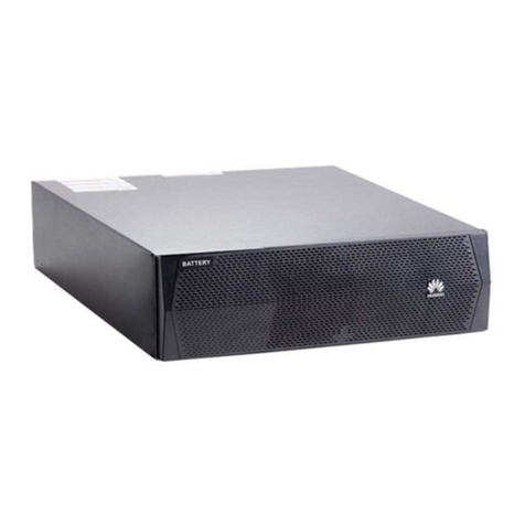
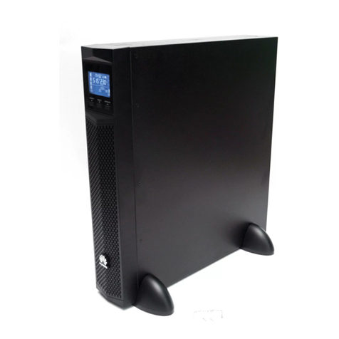
Huawei ESS-240V12-9AhBPVBA Series User manual

Issue: 05
Part Number: 31505551
Date: 2019-01-08
ESS-240V12-(9AhBPVBA,7AhBPVBA)
Battery Pack Quick Installation Guide
Copyright ©Huawei Technologies Co., Ltd. 2019. Allrights reserved.
To ensure safety of humans and the equipment, pay attention to the safety symbols on the
equipment and all the safety instructions in this document. The "NOTE", "CAUTION", and
"WARNING" marks in this document do not represent all the safety instructions. They are only
supplements to the safety instructions. When operating Huawei equipment, in addition to following
the general precautions in this document, follow the specific safety instructions given by Huawei.
Huawei will not be liable for any consequences that are caused by the violation of safety regulations
and design, production, and usage standards.
1Precautions
Safety Precautions
Local Safety Regulations
When operating Huawei equipment, you must follow the local laws and regulations.
Personnel Requirements
1. Only trained and qualified personnel are allowed to install, operate, and maintain Huawei devices.
2. You can modify default parameters only after being granted approval from Huawei technical
support.
Symbols
Indicates a potentially hazardous situation which, if not avoided, could result in
equipment damage.
Data loss, performance deterioration, or unanticipated results.
NOTICE is used to address practices not related to personal injury.
Calls attention to important information, best practices and tips.
NOTE is used to address information not related to personal injury, equipment
damage, and environment deterioration.
Indicates a potentially hazardous situation which, if not avoided, could result in
death or serious injury.
Indicates a potentially hazardous situation which, if not avoided, may result in
minor or moderate injury.
Indicates an imminently hazardous situation which, if not avoided, will result in
death or serious injury.
NOTE
1
Проконсультироваться икупить данное оборудование вы можете вкомпании «АНД-Системс»
адрес: 125480, г.Москва, ул.Туристская, д.33/1; site: https://andpro.ru тел: +7 (495) 545-4870 email: [email protected]
При обращении используйте промокод AND-PDF иполучите скидку.

2
Human Safety
1. Before performing any operation, carefully read this document.
2. To prevent electric shocks, get tools insulated and wear insulation gloves when connecting cables.
3. To prevent personal injury, wear protective shoes when moving batteries.
4. In case of fire, use a dry power fire extinguisher to put out the fire. Using a fluid fire extinguisher
may cause electric shocks.
5. Do not touch uninsulated battery terminals. Otherwise, electric shocks may occur.
6. Using incorrect battery models may cause explosion. Dispose of used batteries by following the
instructions.
7. Cut off power supply and remove all metal objects such as watches and rings before maintenance.
8. Do not move the battery pack by holding its mounting brackets, front panel, or terminal cover.
Because the battery pack is heavy, several persons are required to move it in compliance with
safety regulations.
< 18 kg (< 40 lb) 18–32 kg (40–70 lb) 32–55 kg (70–120 lb) > 55 kg (> 120 lb)
2Appearance
ESS-240V12-(9AhBPVBA,
7AhBPVBA) appearance ESS-240V12-(9AhBPVBA,
7AhBPVBA) rear panel
DC port 1
DC port 2
Battery temperature sensor
cable hole
Battery pack Weight Dimensions (H x W x D)
ESS-240V12-7AhBPVBA01 61 kg
130 mm x 430 mm x 685 mm
ESS-240V12-7AhBPVBA02 51 kg
ESS-240V12-9AhBPVBA01 69 kg
ESS-240V12-9AhBPVBA02 65 kg

3
3Preparations
1. Do not move the battery pack by holding its mounting brackets, front panel, or terminal cover.
2. Remove rings, watches, and other metal objects before you move a battery pack.
No. Item
1Visually inspect the battery pack appearance for shipping damage. If any shipping
damage is found, report it to the carrier immediately.
2Check the battery pack bar code, which is at the rear panel of the UPS, near the DC port,
and ensure that it complies with the order. If there is any discrepancy, contact your local
Huawei office immediately.
Unpacking and Checking
3.2
Tools
3.1
Get installation tools
insulated to prevent
electric shocks.
Torque screwdriver
Wire stripper Polyvinyl chloride
(PVC) insulation tape Cotton cloth Heat shrink tubing (Φ6)
Heat gun Cable tie
Phillips screwdriver
(PH2 x 150 mm or PH3
x 250 mm) Flat-head
screwdriver
Protective gloves Electrostatic discharge
(ESD)gloves Electrician's knife Insulation gloves
Hydraulic pliers Multimeter

4
1. Remove the three screws that secure the
cover of the battery pack.
2. Remove the cover horizontally. If multiple battery packs are installed, install
the battery temperature sensor for only one
battery pack.
4Installation
(Optional) Installing a Battery Temperature Sensor
NOTE
3. Remove the cable hole baffle plate of the battery temperature sensor, rotate the baffle plate 180
degrees, and secure it with the removed screws. Route the battery temperature sensor into the
battery pack through the cable hole, and secure the sensor cable to the cable bridge by using a
cable tie.
4. Reinstall the cover for the battery pack, and secure the cover by using the three removed screws.
Cover
Cable hole baffle plate Cable bridge
Battery
temperature
sensor

5
15kVA/20kVA
UPS
15kVA/20kVA
UPS
15kVA/20kVA
UPS
15kVA/20kVA
UPS
Rack-mounting Battery Packs
NOTE
1. A UPS2000-G-6 kVA/10 kVA requires one battery pack to provide standard backup time, and
requires two to four battery packs to provide long backup time. For a UPS that provides long
backup time, battery packs connect to each other in parallel and then connect to the UPS battery
input port. The following figure shows how to connect four battery packs in parallel.
2. If the number of UPS2000-G-6 kVA/10 kVA parallel system is greater than or equal to 3, each
UPS can be configured with one to four battery packs. The installation methods for each UPS and
battery pack in the parallel system are the same as those in a single UPS system. The installation
sequence is: UPS > battery pack > UPS > battery pack … UPS > battery pack.
A. One 15 kVA/20 kVA UPS + Four battery packs
B. Two 15 kVA/20 kVA UPSs (1+1 parallel
system) + Four battery packs (shared)
C. Two 15 kVA/20 kVA UPSs (1+1 parallel
system) + Eight battery packs (not shared)
3. The following figures show three methods for installing the UPS2000-G-15 kVA/20 kVA and
battery packs.
Battery packs
Battery packs
Battery packs
Battery packs
…
Battery
pack 1
UPS Battery
input
Battery
pack 2
Battery
Pack 3
Battery
Pack 4
Battery cable
Battery
pack 1
UPS Battery
input
Battery
pack 2
Battery
Pack 3
Battery
Pack 4
Battery
pack 1
UPS Battery
input
Battery
pack 2
Battery
Pack 3
Battery
Pack 4
Battery
pack 1
UPS Battery
input
Battery
pack 2
Battery
Pack 3
Battery
Pack 4

6
1. Install mounting brackets.
This document uses a 19-inch rack as an example. For other racks, see the related UPS quick
installation guide.
2. Install battery packs. There are two methods.
Method 1: Floating nuts + Common guide rails
Align the lower plane of the guide rail with the lower edge of a U scale. Install
floating nuts (six in total) in positions numbered 2, 5, and 8, as shown in the
following figure.
Lower edge of
a U scale
Common guide rail
1 U
M4x8 (8 PCS)
1.2 N•m
NOTE

7
A. Fix the position of the guide rails (2 U) on the rack align the lower edge of a guide rail
with the lower edge of a U scale.
B. Engage the mounting brackets on both ends of the guide rail into the mounting holes,
and then secure the back end of the guide rail with M6x16 panel screws. Do not install
panel screws on the front end of the guide rail. Use the same method to install the
other guide rail.
C. Install floating nuts in the upper part of the guide rails (front side) on both sides. The
following figure shows the installation positions.
Method 2: Adjustable guide rails (optional) + Floating nuts
Lower edge of
a U scale
The guide rail on the right has the R silkscreen, and the
guide rail on the left has the L silkscreen. Do not install
them reversely.
Floating nut
Mounting bracket notch
Guide rails are optional and recommended for rack installation. For a 3 U device, install guide rails
and two floating nuts. Secure the device with screws. The floating nuts are delivered with the rack.
1U
M6×16(4PCS)
3N•m
NOTE

8
3. Place the battery pack on the guide rails. Secure the battery pack to the rack using M6x16 screws
through the holes in the mounting bracket.
1. Do not move the battery pack by holding its mounting brackets, front panel, or terminal cover.
2. Remove rings, watches, and other metal objects before you move a battery pack.
3. Do not push the guide rails out of the race when putting the battery pack into the rack, as the
front end of the guide rails are not screwed.
Ensure that the rack is properly grounded
before the operation. Do not touch uninsulated battery terminals.
Otherwise, electric shocks may occur.
Tower-mounting Battery Packs
1. The text uses how to install a battery packs and a 6 kVA UPS as an example.
2. The support base length is adjustable. You can add components to increase the length. A
component (1 U) installed between the support bases is required for a 3 U device.
3. Exert force to disassemble components in the reverse directions of assembling.
4. The minimum distance between two support bases should be 280 mm and the maximum should
not exceed the edge of the device. It is recommended that the distance between the front (rear)
base and the front (rear) side of the device should be about 100 mm.
NOTE
1. Assemble support bases. When you assemble two support bases, align connecting buckles with
holes and insert the buckles vertically, as shown in the following figure.
2. Install two groups of support bases for each group of battery packs as follows: Place support
bases on the floor, determine the distance (greater than or equal to 280 mm) between the two
groups of support bases, place battery packs on the support bases in sequence, and secure them.
M6×16(6PCS)
3N•m

9
3. After the battery packs are tower-mounted, seal the four screw holes on the top with rubber
plugs that are delivered with the battery packs.
6kVA UPS
Support
base
Connecting
buckle
Components
installed
between
support
bases
Battery packs
Rubber plugs
1. A UPS2000-G-6 kVA/10 kVA requires one battery pack to provide standard backup time, and
requires two to four battery packs to provide long backup time. For a UPS that provides long
backup time, battery packs connect to each other in parallel and then connect to the UPS
battery input port. (See page 4.)
2. If the number of UPS2000-G-6 kVA/10 kVA parallel system is greater than or equal to 3, each
UPS can be configured with one to four battery packs. The installation methods for each UPS
and battery pack in the parallel system are the same as those in a single UPS system. The
installation sequence is: UPS > battery pack > UPS > battery pack … UPS > battery pack. For
details, see page 5.
3. If the UPS2000-G-15 kVA/20 kVA 1+1 parallel system does not share battery packs, install
eight battery packs. For the installation sequence, see the rack-mounted method on page 5.
When to disassemble components use protective gloves to protect hands.
NOTE

Item Appearance Remarks
Battery
cable 01
Standard
configuration,
connecting the
battery packs, or
connecting battery
pack and the
UPS2000-G-6
kVA/10 kVA
Battery
cable 02
Optional
configuration,
connecting the
battery pack and the
UPS2000-G-15
kVA/20 kVA
10
Open the circuit breaker of the external battery pack or battery rack (if there is), load circuit breaker,
front-end input circuit breaker, and UPS AC input circuit breaker. Then connect cables.
5Cable Installation
NOTE
1. When connecting cables, first connect cables to the UPS, and then insert the cables to terminals
on the battery cabinet. When removing cables, first disconnect the cables from the battery cabinet,
and then cables from the UPS.
2. Determine cable colors based on industry standards.
3. For the cable connecting the battery packs, connecting battery pack and the UPS2000-G-6
kVA/10 kVA UPS BATT.240 V DC terminal, both ends are PP45 terminals. See Battery cable 01
in the following table.
4. For the cable connecting the battery pack and the UPS2000-G-15 kVA/20 kVA UPS BATT.±240
V DC terminal, one end is a PP45 terminal (connected to the battery pack), and the other end is a
M6 OT terminals that are 90 degrees bent and have a cross-sectional area of 16 mm²(connected
to the UPS). See Battery cable 02 in the following table.
5. The standard battery pack for the UPS2000-G-6 kVA is ESS-240V12-7AhBPVBA, and the
standard battery pack for the UPS2000-G-10 kVA is ESS-240V12-9AhBPVBA. When the
UPS2000-G-15 kVA/20 kVA connects to four battery packs (two battery packs of each group are
connected in parallel and then the two groups are connected in series), ESS-240V12-7AhBPVBA
and ESS-240V12-9AhBPVBA can be used.
6. If customers purchase input and output power cables by themselves, use the cables that comply
with standards proposed by Underwriters Laboratories (UL) or International Electrotechnical
Commission (IEC).
Red
Black
Green and
yellow
Red
Black
Green
and
yellow
Red
Black

11
Connecting Cables to Battery Packs for a Single UPS2000-G-6 kVA/10 kVA
UPS
BATT.240V DC port
Connecting Cables to Battery Packs for a UPS2000-G-6 kVA/10 kVA Parallel System
UPS2
BATT.240V DC port
UPS1
BATT.240V DC port
Connecting Cables to Battery Packs for the UPS2000-G-6 kVA/10 kVA
NOTE
NOTE
NOTE
For the number of battery packs required by a UPS2000-G-6 kVA/10 kVA that provides standard or
long backup time, see page 5. The following figure shows how to connect a UPS that provides
standard backup time to a battery pack.
1. For the number of battery packs required by a UPS2000-G-6 kVA/10 kVA parallel system that
provides standard or long backup time, see page 5. The following figure shows how to connect
each UPS that provides standard backup time in a parallel system to a battery pack.
2. If the number of UPS2000-G-6 kVA/10 kVA parallel system is greater than or equal to 3, each
UPS can be configured with one to four battery packs. The cable connection methods for each
UPS and battery pack in the parallel system are the same as those in a single UPS system.
A UPS2000-G-6 kVA/10 kVA requires one battery pack to provide standard backup time, and requires
two to four battery packs to provide long backup time. For a UPS that provides long backup time,
battery packs connect to each other in parallel and then connect to the UPS battery input port. (See
page 5.)

12
Connecting Cables to Battery Packs for the UPS2000-G-15 kVA/20 kVA
1. A 15 kVA/20 kVA UPS with long backup time requires serial connection of two battery packs in
each group. A maximum of four groups with eight battery packs can be connected in parallel. If
more than two battery packs need to be connected to the 15 kVA/20 kVA UPS with long backup
time, the battery packs should be connected in parallel and then connected to the battery input
ports of the UPS, as shown in the following figure. Battery packs 1 and 2, battery packs 3 and 4,
battery packs 5 and 6, and battery packs 7 and 8 are connected in series respectively. Battery
packs 1, 3, 5, and 7 are connected in parallel. Battery packs 2, 4, 6, and 8 are also connected in
parallel.
NOTE
A. Battery pack connections for a single 15 kVA/20 kVA UPS
B. Battery pack connections for parallel 15 kVA/20 kVA UPSs
2. If the UPS2000-G-15 kVA/20 kVA 1+1 parallel system does not share battery packs, the cable
connection methods for each UPS and battery pack in the parallel system are the same as those
in a single UPS system.
UPS 1
BATT.±240 V DC port UPS 2
BATT.±240 V DC port
UPS
BATT.±240 V DC port

13
UPS
BATT.±240 V DC port
Connecting Cables to Battery Packs for a Single UPS2000-G-15 kVA or
UPS2000-G-20 kVA
When a UPS2000-G-15kVA/20 kVA requires two battery packs, set the Max. current parameter less
than or equal to 2.0 A.
A 15 kVA/20 kVA UPS with long backup time requires serial connection of two battery packs in each
group. A maximum of four groups with eight battery packs can be connected in parallel. The text
uses four battery packs in two groups as an example. If more than four battery packs need to be
connected, refer to the connection method illustrated on page 10.
NOTE

UPS 1
BATT.±240 V DC port UPS 2
BATT.±240 V DC port
14
Connecting Cables to Battery Packs for a UPS2000-G-15 kVA or
UPS2000-G-20 kVA Parallel System
If the UPS2000-G-15 kVA/20 kVA 1+1 parallel system does not share battery packs, the cable
connection methods for each UPS and battery pack in the parallel system are the same as those in a
single UPS system.
NOTE
NOTE
Install the battery pack front panel after cables are properly connected.

15
Huawei Technologies Co., Ltd.
Huawei Industrial Base, Bantian, Longgang
Shenzhen 518129 People's Republic of China
www.huawei.com
This manual suits for next models
5
Table of contents
Other Huawei Batteries Pack manuals

Huawei
Huawei ESS-240V12-9AhBPVBA04 User manual

Huawei
Huawei LUNA2000-2.0MWH Series User manual

Huawei
Huawei LUNA2000-5-S0 User manual

Huawei
Huawei SmartLi 2.0 User manual

Huawei
Huawei LUNA2000 Series User manual

Huawei
Huawei UPS2000-G-1 kVA User manual

Huawei
Huawei ESS-240V12-16AhBPVBB User manual

Huawei
Huawei LUNA2000 7-S1 User manual

Huawei
Huawei LUNA2000-15-S0 User manual

Huawei
Huawei ESS-240V12-9AhBPVBA03 User manual