ENERCON SUPER SEAL 300 User manual
System Setup & Connections
Enercon Industries, Ltd. Aylesbury, Bucks UK
Tel: +44 1296 330542
E-mail: info@enerconind.co.uk
Enercon Industries Corp. Menomonee Falls, WI USA
Tel: +1-262-255-6070
www.enerconind.com/sealing/support
Super SealTM 300/400/600 Quick Start Guide
See included diagrams and manuals for more detailed information.
Raise
Mounting
Bolts
Locking
Knob
Center Line
Label
1
Guide
Rails
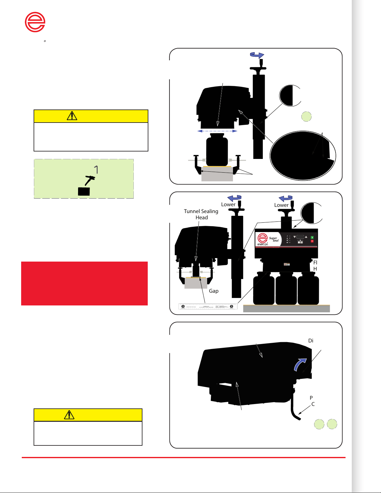
1Align sealing head and container
a. Use guide rails to ensure a consistent
container path beneath the sealing head.
b. Ensure there is no metal within 6”
of sealing head.
c. Ensure the Sealer’s height allows
containers to pass beneath the sealing head.
d. Center the sealing head over the container.
CAUTION!
The sealing head’s magnetic eld will
quickly heat any metal that enters the
eld! Keep all metal beneath the sealing
head out of the eld!
i.
2Set the air gap over container
a. The recommended gap is 1/8” (3mm).
b. Place containers and the gapping tool
beneath the sealing head.
c. Lower the sealing head and ensure the
gap is even along it’s full length.
Lower
Flat Sealing
Head
Lower
Gap
Gauge
Tunnel Sealing
Head
Locking
Knob
2
Disconnect
Switch
Stack Light
Cable Connection
Rating
Plate
Power
Cord
iii.
ii.
3
3Connecting and applying input voltage
a. All systems require an input voltage range
of either 200 - 240 VAC 1Ø.
Refer to your system’s rating plate.
b. If included, plug the stack light into its
connector.
c. Rotate the disconnect switch to the ON
position.
d. The front panel will display 50% factory
set point.
e. Proceed to the Basic Operation Quick
Start Guide.
Observe all safety precautions when
connecting the system to its input
voltage!
CAUTION!
i. 6mm Allen Wrench Step 1
ii. Wire Strippers Step 3
iii. Screwdriver Step 3
Required Tools:
Installation should be performed by
qualied professionals and include a
full risk assessment of the entire line.

1
The Super Seal™ Induction Cap Sealer utilizes a Digital Display and Pushbuttons to monitor and
control the power supply output and settings.
2
System Basic Operation
Super SealTM 300/400/600 Quick Start Guide
Enercon Industries, Ltd. Aylesbury, Bucks UK
Tel: +44 1296 330542
E-mail: info@enerconind.co.uk
Enercon Industries Corp. Menomonee Falls, WI USA
Tel: +1-262-255-6070
www.enerconind.com/sealing/support
See included diagrams and manuals for more detailed information.
How to nd your induction
sealing operating window
The window is the range between the minimum & maximum power levels that achieve a good seal. After
determining your operating window, select a power level within this range to run production based on the
desired seal strength and peelability your product requires.
Try sealing your rst container at 50% power. Follow the instructions below based on your results until you determine the minimum power level that achieves
a good seal. Be sure your conveyor speed is set to your actual production rate.
Seal your rst container at a power level that produces a good seal. Follow the instructions below based on your results until you determine the maximum
power level that achieves a good seal.
Try next container @ +5% power Try next container @ -5% power
Try next container @ -5% power
Try next container @ -1% power until you reach
the minimum power that achieves a good seal
then proceed to step two
Try next container @ +1% power until you
reach the maximum power that achieves a
good seal
No Seal Partial Seal Overheated Seal
Overheated Seal
Good Seal
Good Seal
1Find the Minimum Power Level that Produces a Good Seal
2Find the Maximum Power Level that Produces a Good Seal
MIN
MIN
MAX
MAX
OPERATING WINDOW
OPERATING WINDOW
Start
Stop
OK: Press to select and acknowledge changes.Menu: Press to enter and exit Setup Mode.
Display Meter
Displays the output %
and setup information.
Increase
Increases the output %,
scrolls up through settings
and enables modes.
Decrease
Decreases the output %,
scrolls down through settings
and enables modes.
Idle/Local/No Fault Running Fault Remote
Run
Fault
Start/Stop
Controlled
Remotely
Power Level
Controlled
Remotely
LED Indicators
100
MENU ITEMS
S/S
LEV
STL
DIR
EJD
EJT
MSF
ALM
SEN
FAC
= Start/Stop Control Mode
= Level Control Mode
= Stalled Bottle Timer Setting
= Direction Setting
= Eject Delay Setting
= Eject Time Setting
= Missing Foil Output Setting
= Alarm Setting
= Sensor Diagnostic Mode
= Factory Reset
Other manuals for SUPER SEAL 300
1
This manual suits for next models
2
Other ENERCON Industrial Equipment manuals

Popular Industrial Equipment manuals by other brands

Gema
Gema UA05-X Operating instructions and spare parts list

Shurco
Shurco 3500 Series quick start guide

OEM Tools
OEM Tools 87032 Operating instructions and parts manual

Premier Manufacturing Co.
Premier Manufacturing Co. 820ELA Service guidelines

Ebmpapst
Ebmpapst A3G630-AD03-A8 operating instructions

ABB
ABB HT563033 Operation manual


