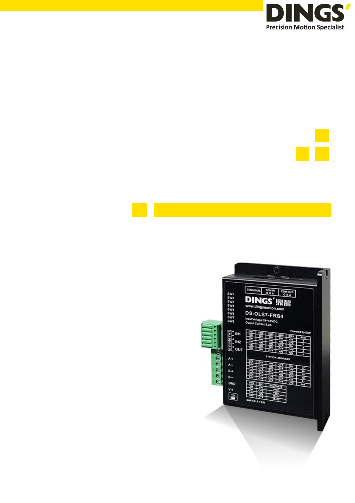
Dings DS-OLS7-FRS4 User manual
page│1
Technical Manual
DS-OLS7-FRS4
DS-OLS7-FRS4 Technical Manual
VER 1.0

page│2
Table of Contents
1.
Features…………………………………………………………………………...………………3
2. Technical Parameters…………………………………………………………...........……………...3
3. Schematic and Interface Definition...........................................................................................4
4. Power Supply…………………………..……………………………………………………………....8
4.1
Voltage…………………………………………………………………………….……………….8
4.2
Current…………………………………………………………………………………………….. 8
4.3
Regeneration of Discharge……………………………………………………………………...8
5. Motor Connection……………………………………………………………………………..……….9
6. Signal Input………………………………………………………………………………………...…10
6.1
Pulse Signal :STEP…………………………….…………………………..……………………10
6.2
Direction Signal : DIR……………………………………………………………………………10
6.3
Pulse / Direction Input Timing diagram…………………………………………..…………….11
7. Typical Signal Connection……………………………………………………………...…………....12
7.1
Common Positive Connection…………………………………………………………………12
8. Typical Connection of Signal Output………………………………………………………………...13
8.1
Relay Connection…………………………………………………………..…………………....13
8.2
Optocoupler Connection……………………………………………………..………………….13
9. Wiring Requirements………………………………………………………………………………....14
10. Installation Dimensions……………………………………………….…………………………….15
11. Control Parameter………………………………………………………………………………….16
11.1
Control Basic Status (Class 01)………………………………………...……………………..16
11.2
Basic Parameter Setting (Class 02)…………………………………………………………..16
11.3
Control Parameters (Class 05)………………………………………………………………...17
11.4
Input Block Designation (Class 06)……………………………………..……………………..19
11.5
Output Block Specification (Class 07)………………………………………………………..21
12. Modbus-RTUProtocol Example...…………………………………………...……………………..22
12.1
Running Motor……………………………………………………………………………..…....22
12.2
Read Motor Status..........................…………………………………………………………...26
12.3
Read Alarm Status......................……………………………………………………………....28
13. Part……………………………………………………………………………...……………………..29
Click to return to table of contents
Contents

page│3
1. Features
Input power: DC 24V-48V
PWM constant current bipolar subdivision drive
Single / double pulse selection
Optically isolated input function
Motor short circuit protection
Compact design, low noise and low vibration
Adjustable driving current peak below 3.2 A
Support RS 485 communication
2. Technical Parameters
STEP Drive model DS-OLS7-FRS4
Adapter motor Adapted to two-phase hybrid stepping motor, DS-OLS7 FRS4
Maximum fit 3.2A
Power supply 24 - 48V DC
Output current DS-OLS7-FRS4:0.1A-3.2A/ phase
Drive mode Full-bridge bipolar PWM driver
Input signal IN1(DIR)signal Optocoupler input voltage H = 3.5 - 26.0V , L = 0 - 0.8V
On current 6-15mA
IN2(STEP)signal
Output signal OUT Output Optically isolated output, highest withstand voltage30VDC,
Maximum saturation current 50mA
Size 94 × 77 × 27mm(Including terminal block)
Weight About 175 g
Use
surroundings
Use occasion Avoid dust, oil mist and corrosive gases
Humidity < 85 % RH, No condensation
Temperature 0°C - +40°C
Heat dissipation Installed in a ventilated environment
Features / Technical Parameters

page│4
3. Schematic and Interface Definition
1) Signal input (as shown from left to right)
Operation mode selection 0: external pulse
1 pin --- pulse STEP +, 2 pin --- pulse STEP-, 3 pin --- direction DIR +, 4 pin --- direction DIR-
5 feet --- output OUT +, 6 feet --- output OUT-
Operation mode selection 1: internal pulse
Pin 1 --- Input port IN1 +, Pin 2 --- Input port IN1-, Pin 3 --- Input port IN2 +, Pin 4 --- Input port IN2-
Pin 5 --- Output OUT +, Pin 6 --- Output OUT-
2) Motor connection and power input (as shown from left to right)
1 pin --- A +, 2 pin --- A- 3 pin --- B +, 4 pin --- B-, 5 pin --- V-, 6 pin --- V +
3) RS485 IN / RS485 OUT(side)
1 pin --- A, 2 pin --- B 3 pin --- GND
Setting Switch
Schematic and Interface Definition

page│5
4) mailing address
Users can control up to 30 DS-OLS7-FRS4 drives simultaneously using the RS-485 bus.
The drive communication address setting uses a 5-digit DIP switch.
The address setting range is 1-32, where address 32 is reserved for the system. When the
drive address setting is greater than 31, it needs to be set and saved using the upper
debugging software.
And the switch must be set to all OFF (default is 1).
Notes
1)
One controller can control up to 30 DS-OLS7-FRS4 drives simultaneously via
the RS-485 bus.
2) The communication address setting of each drive must be unique,
otherwise it will cause communication error.
DIP switch
address
SW1
SW2
SW3
SW4
SW5
ON ON ON ON ON 1
ON ON ON ON OFF 2
ON ON ON OFF ON 3
ON ON ON OFF OFF 4
ON ON OFF ON ON 5
ON ON OFF ON OFF 6
ON ON OFF OFF ON 7
ON ON OFF OFF OFF 8
ON OFF ON ON ON 9
ON OFF ON ON OFF 10
ON OFF ON OFF ON 11
ON OFF ON OFF OFF 12
ON OFF OFF ON ON 13
ON OFF OFF ON OFF 14
ON OFF OFF OFF ON 15
ON OFF OFF OFF OFF 16
OFF ON ON ON ON 17
OFF ON ON ON OFF 18
OFF ON ON OFF ON 19
OFF ON ON OFF OFF 20
OFF ON OFF ON ON 21
OFF ON OFF ON OFF 22
OFF ON OFF OFF ON 23
Schematic and Interface Definition
page│6
OFF ON OFF OFF OFF 24
OFF OFF ON ON ON 25
OFF OFF ON ON OFF 26
OFF OFF ON OFF ON 27
OFF OFF ON OFF OFF 28
OFF OFF OFF ON ON 29
OFF OFF OFF ON OFF 30
OFF OFF OFF OFF ON 31
OFF OFF OFF OFF OFF N/A
5)Communication baud rate
DIP switch
Baud rate (bps)
SW6
SW7
ON
ON
4800
ON
OFF
9600
OFF
ON
19200
OFF
OFF
38400
6)Test run
The commissioning function is used to verify the performance of the drive. Turn the SW8
switch to ON when the power is off. Then, after power-on, without pulse input, the SW8
gear dial switch is turned from the ON position to the OFF position. After 1 second, the
OFF position is set to the ON position, that is, the test run function is started (the motor is
at 1 rev/sec. The speed of the cycle is positive and negative movements in a circle).
7)DIP switch (SW9-10) setting
Set the terminal resistance to ON/OFF
Please set both switches of the final node to ON only.
Never set more than two device switches to ON.
Schematic and Interface Definition

page│7
8)Idle current
After 500 milliseconds of no pulse input, the current will automatically enter the idle current
to reduce motor heating. The current is restored to the set value during pulse input.
9)Indicator function
This product has 2 LEDs indicating that the light shows the working status:
1. Green light: (work instructions)
When the motor has no current, the lamp flashes 2 times (0.5 second low level, 0.5 second
high level) to complete the 2 second high level, and then recirculate.
It is always on when the motor is running.
The lamp flashes when the motor is running (0.5 second low level, 0.5 second high level).
2. Red light: (fault indication)
Mode: Blinking (0.5 sec low level, 0.5 sec high level) times to complete 2 seconds high level,
then recirculate.
Alarm function Flashing light Description
Motor overcurrent Constantly bright Motor phase current overcurrent or driver failure
Motor phase loss Flashing once The motor is not connected
Power overcurrent 2 flashes Power overcurrent or drive failure
Undervoltage 3 flashes Power input is less than 18V
Overpressure 4 flashes Power input is greater than 52V
overheat 5 flashes Drive heatsink temperature above 80 °C
overload 8 flashes Brake resistor failure
other other Other failure
Schematic and Interface Definition

page│8
4. Power Supply
4.1 Voltage
The chopper driver continuously changes the size and direction of the motor winding voltage
and detects the current to obtain accurate phase current. If both high efficiency and low noise
are to be ensured, the driver supply voltage shall be at least 5 times the motor rated phase
voltage (that is, the motor rated phase current × phase resistance).
If you need the motor to get better high speed performance, you need to increase the driver
supply voltage.
If power is supplied from a regulated power supply, the supply voltage shall not exceed 48V.
If non-stabilized power supply is used, the voltage shall not exceed 34V.
Because the rated current of non-stabilized power supply is full load current ; When the load is
light, such as when the motor is not running, the actual voltage is up to 1.4 times the rated
voltage of the power supply. For smooth and quiet operation of the motor, choose low voltage.
4.2 Current
The maximum supply current shall be the sum of the two phase currents. Usually, the amount
of current you need depends on the type of motor, voltage, speed, and load conditions. The
actual supply current value is much lower than this maximum value, because the driver USES
a switching amplifier that converts high voltage and low voltage current into low voltage and
high current. The more the supply voltage exceeds the motor voltage, the less supply current
is required. When the motor is connected to a 48V power supply, the output current of the
power supply is half of that of the 24V power supply.
4.3 Regeneration of Discharge
When the motor slows down, it ACTS like a generator, converting the kinetic energy of the load into
electricity. Some energy is consumed by the driver and motor. If your application has a large load
running at high speed, a considerable amount of kinetic energy can be converted into electricity.
Easy to cause the drive alarm (overvoltage) may even cause damage to the drive.
Since this driver has the function of anti-power connection, it can prevent the driver
damage caused by power connection, so the use of external regenerative discharge
device does not work.
When your application has a large load running at high speed, please contact the
company in advance, shield anti - reverse connection function, and external
Power Supply
page│9
regenerative discharge device. Please note that the positive and negative terminals of
the power supply should not be inversely connected when there is no anti-inversely
connected function.
The driver damage caused by inversely connected power supply cannot be guaranteed.
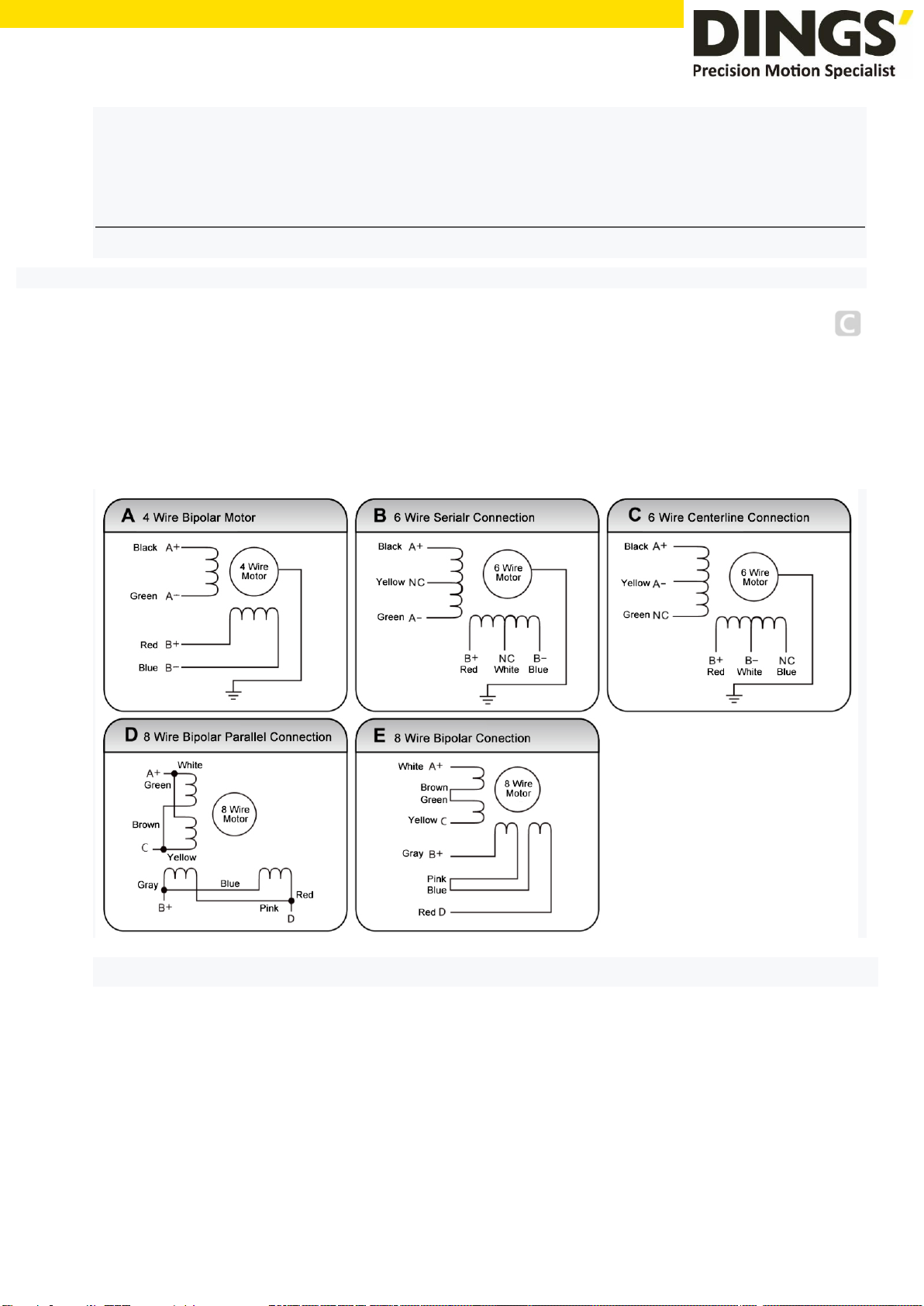
5. Motor Connection
Warning: When connecting the motor to the drive, first make sure that the power of the drive is
turned off. Make sure that the unused motor leads are not short-circuited with other objects.
The motor cannot be disconnected while the drive is energized. Do not connect motor leads to
ground or power.
1) Four-wire motors can only be connected in one way.
2) Six-wire motors can be connected in two ways: full group and half group. In the full group mode, the
motor has greater torque at low speeds, but it cannot run as fast as in the half group. When the whole
group is running, the motor needs to run at less than 30% of the half-group current to avoid overheating.
3) Eight-wire motors can be connected in two ways: series and parallel. The series mode has greater
torque at low speeds and less torque at high speeds. When running in series, the motor needs to run
at 50% of the current in parallel to avoid overheating.
Power Supply / Motor Connection

page│10
Notes
1) The corresponding colors of different motors are different. When using the
motors, the specifications of the motors shall prevail. For example, the colors of
57 and 86 motor wires are different.
2) The phases
are relative, but the windings of different phases cannot be
connected to the terminals of the same phase of the driver (A +, A- is one phase,
B +, B- is the other phase). If the motor direction is different from the expected
direction, only A + , A-.
3) This driver can only drive two-phase hybrid stepping motors, not three-phase
and five-phase stepping motors.
4) The method of judging whether the stepper motor is connected in series or in
parallel: Rotate the shaft of the motor directly by hand without connecting the
driver. If it can rotate easily and evenly, it means that the wiring is correct. If it
encounters large resistance and unevenness Accompanied by a certain sound
indicating that the wiring is incorrect.
6. Signal Input
6.1 Pulse Signal : STEP
The driver port has a built-in optocoupler, which can accept 5-24VDC single-ended or
differential signals, and the highest voltage can reach 26V. Its change from off to on is
understood as accepting a valid pulse edge command. For the common anode, the low level
is valid (the common negative is valid for the high level). At this time, the driver will drive the
motor to run one step according to the corresponding timing. For the normal operation of the
driver, the duty cycle of the effective level signal should be below 50%. In order to ensure the
reliable response of the pulse signal, the duration of the pulse effective level of the subdivided
driver should not be less than 1us. The signal response frequency of the subdivision driver is
500KHz, and an excessively high input frequency may get an incorrect response.
6.2 Direction Signal : DIR
Can accept 5-24VDC single-ended or differential signals, the highest voltage can reach 26V.
The on / off of the internal photocoupler at this end is interpreted as two directions of motor
operation. The change of the direction signal will change the direction of motor operation. The
floating of this end is equivalent to the input high level. It should be noted that the subdivision
driver should ensure that the direction signal is established at least 10us ahead of the pulse
signal input to avoid the driver s incorrect response to the pulse signal. When the motor is
commutated, it must be switched after the motor decelerates and stops to the starting
Motor Connection / Signal Input
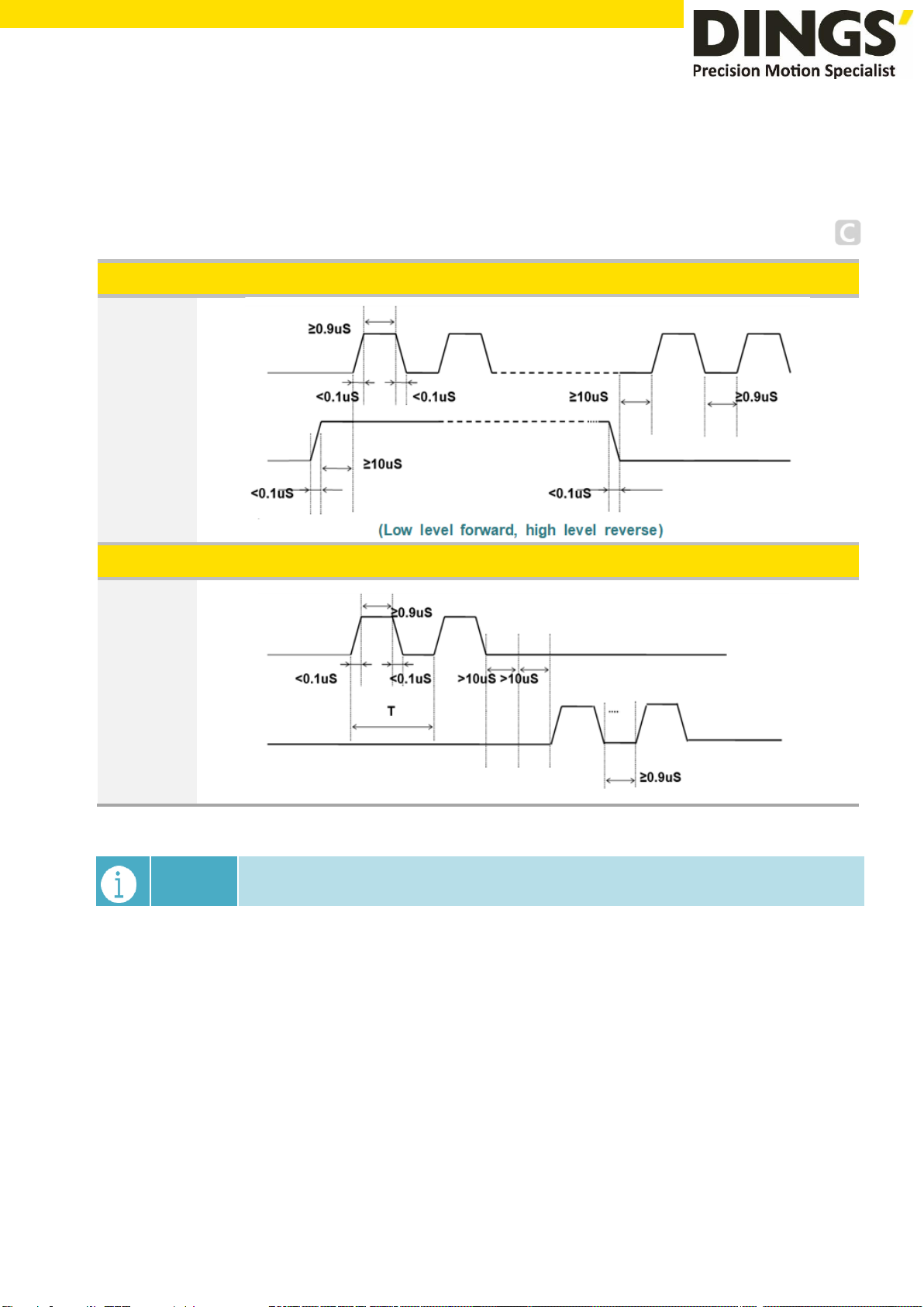
page│11
frequency. The commutation signal must be changed after the last STEP pulse of the previous
direction signal and before the first STEP pulse of the next direction. When no commutation is
required, the direction signal terminal can be left floating.
6.3 Pulse / Direction Input Timing Diagram
Input signal waveform and timing (single pulse method)
STEP Input
DIR Input
Input signal waveform and timing (double pulse method)
STEP Input
(Forward)
DIR Input
(Reverse)
Notes When the driver is set to e
xternal pulse control, IN1 is the STEP pulse input port
and IN2 is the DIR direction input port.
Signal Input

page│12
7. Typical Signal Connection
7.1 Common Positive Connection
Notes The pulse and direction terminals have a constant current input function, which
can be directly connected to the input signal without external series resistor step-
down current limiting protection. The VCC value is 3.5-26V.
Typical Signal Connection
page│13
8. Typical Connection of Signal Output
8.1 Relay Connection
Notes When the relay is connected, it is required to connect diodes at both ends of the
relay (such as IN4000 series)
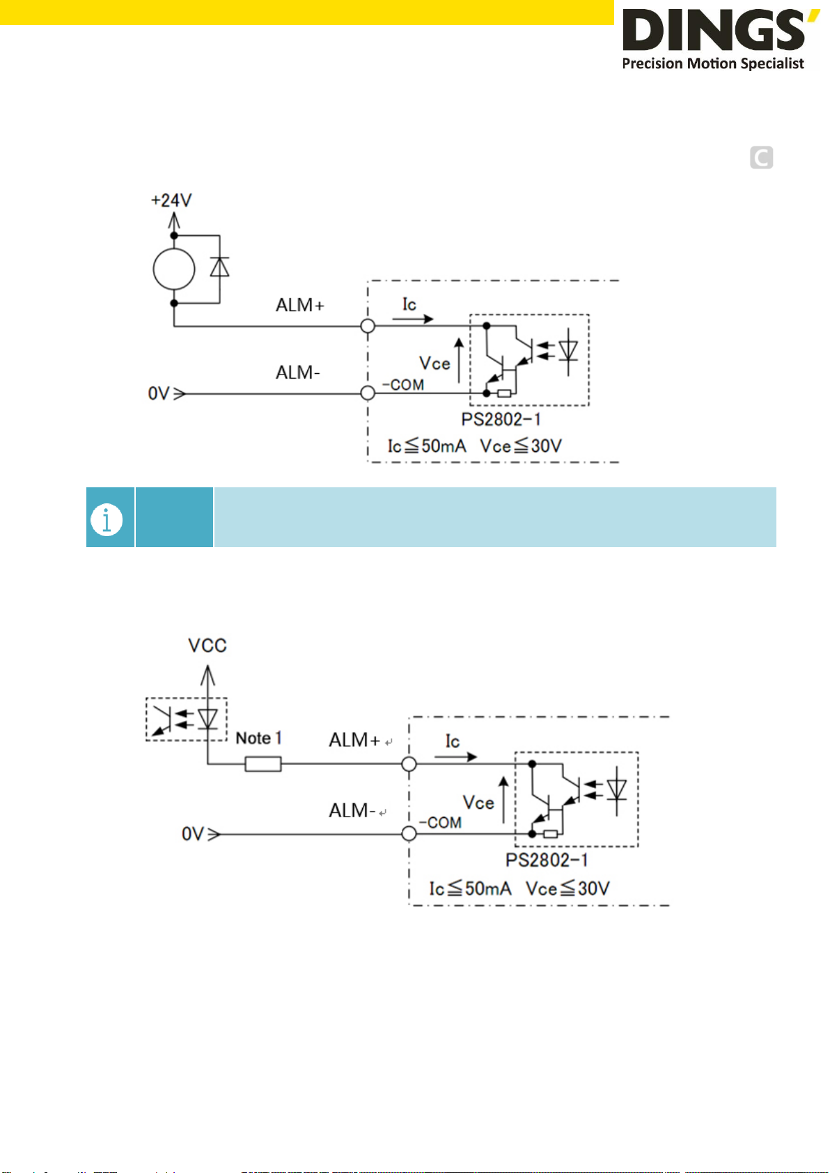
8.2 Optocoupler Connection
The alarm output is optically isolated, with a maximum voltage of 30VDC and a maximum
saturation current of 50mA.
When the driver is working normally, the output is closed.
When the drive fails, the output is left floating.
Typical Connection of Signal Output

page│14
example
Connecting with Keyence products
Typical Connection of Signal Output / Wiring Requirements
9. Wiring Requirements
1) In order to prevent the driver from being disturbed, it is recommended to use shielded cable
for the control signal, and the shield layer should be shorted to the ground. Except for special
requirements, the shielded wire of the control signal cable is grounded at one end: the upper
end of the shielded cable is grounded The driver end of the wire is left floating. Grounding
can only be performed at the same point in the same machine. If it is not a real ground wire,
the interference may be serious, and the shielding layer is not connected at this time.
2) Pulse and direction signal lines and motor lines are not allowed to be bundled side by side,
preferably at least 10cm apart, otherwise motor noise may easily interfere with pulse direction
signals, causing inaccurate positioning of the motor, system instability and other faults.
3) If one power supply is used for multiple drives, a parallel connection should be adopted at the
power supply. It is not allowed to connect one to the other in a chain.
4) It is strictly forbidden to plug and unplug the drivers strong current (motor and power)
terminals. When the charged motor is stopped, a large current still flows through the coil.
Plugging and unplugging the strong current (motor and power) terminals will cause a huge
momentary induced electromotive force to burn out. driver
5) It is strictly forbidden to add lead to the terminal after adding tin, otherwise the terminal may
be damaged due to overheating due to the increased contact resistance.
6) The wiring head must not be exposed outside the terminal to prevent the driver from being
accidentally shorted.
page│15
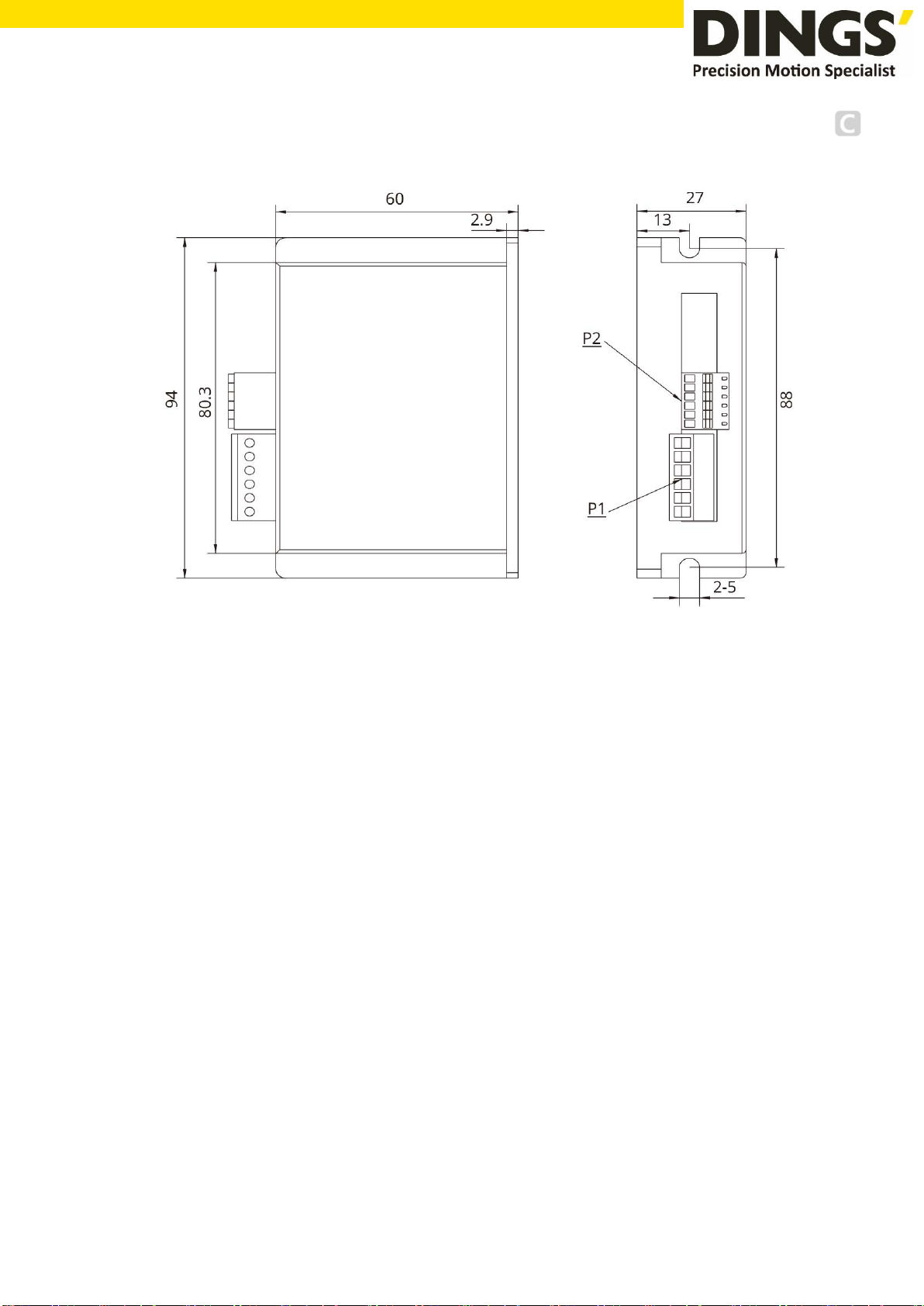
10.Installation Dimensions (unit : mm)
[ Drive installation ]
Install with narrow sides, and install with M3 / M4 screws through the holes on both sides.
The power device of the driver will generate heat. If it works continuously under high input
voltage and high power conditions, it should expand the effective heat dissipation area or
force cooling.
Do not use in places where air circulation is not allowed or where the ambient temperature
exceeds 40 ° C; do not install the drive in humid or metal shavings.
Installation Dimensions

page│16
11. Control Parameter
Notes
Informal version of communication parameters, some parameters are fixed
and not open.
11.1 Controller Basic Status (Class 01)
adr word content Elaborate Range / unit
0100 1 Motor current Motor real-time current value 0.1%A
0101 1 Input voltage Current input voltage 1%V
0104 2 Set up segmentation Set segmentation value ppr
0106 1 Pulse mode 1 is pulse + direction mode, 2 is double
pulse mode
1-2
0108 1 error code Code at the time of alarm, see 1-2 for
content, and display "0" for no fault
-
0109 1 Operating status Drive running status, see 1-1 -
0110 1 hardware version Drive hardware version -
0111 1 Software version Drive software version -
0117 2 current position target location pulse
0119 1 Actual speed display - 0.01rps
0126 2 Actual location Run real-time location pulse
0174 1 IO select multiple run paragraphs - -
0176 1 Multi-segment writing error No - -
0178 1 Multi-stage operation - -
11.2 Basic Parameter Setting (Class 02)
adr word content Elaborate Range / unit
0201 1 Motor direction switching Select the motor running direction 0~1
0206 1 User instructions Set when the motor is stopped
1: user parameter reset
2: Clear the alarm (except for some
hardware failure alarms)
3: drive restart
0~5
0213 1 Half-flow ratio
Stop current ratio (effective in open
loop mode)
10%~120%
0224 1 Angular filtering The smaller the value, the smoother the
motor runs, but the higher the delay
1~700
0234 1 Digital filtering
Filter coefficient of input pulse. The
larger the value, the lower the input
1~15
Control Parameter

page│17
frequency response.
0241 1 Input Current Set current 100~3200
0.1A~-3.2A
0242 2 Set up segmentation Pulses per revolution 200~102400
ppr
0244 1 Pulse mode 1: Pulse + direction mode
2: double pulse mode
1~2
0245 1 Half-flow time
Delay time when the motor stops
running and enters half flow state
(open loop mode is valid)
1~32767
ms
0296 1 Selection of operating mode 0: external pulse
1: internal pulse
Default: 0
Note: After the function is modified,
you need to power off and restart
0~1
0298 1 mailing address Default: 1 1~255
0299 2 Communication baud rate Default: 19200 1600~115200
11.3 Control Parameters (Class 05)
adr word content Elaborate Range / unit
0301 1 Starting frequency Default:100 1~2000
0.01~20rps
0302 1 Stop frequency Default:100 1~2000
0.01~20rps
0303 1 Acceleration Default:100 5~10000
rps2
0304 1 deceleration Default:100 5~10000
rps2
0305 1 Return to origin mode Return to origin mode,
0: Return to origin clockwise
1: Return to the origin counterclockwise
0~1
0306 1 Fixed-length running speed Default: 1000 1~5000
0.01~50rps
0307 1 Speed mode running speed In speed mode, the running direction is
consistent with the speed direction
Default: 1000
-5000~5000
-50~50rps
0308 1 Jog running speed Default: 1000 1~5000
0.01~50rps
Control Parameter

page│18
0309 1 Home speed Default: 1000 1~5000
0.01~50rps
0310 1 Creeping speed Running speed after hitting the origin
Default: 1000
1~5000
0.01~50rps
0311 2 Home offset Default: 0 -2000000000~
2000000000
pulse
0313 2 Output pulse Running stroke
Absolute position mode: run to the
specified position
Relat
ive position mode: travel setting
offset stroke
Default: 0
-2000000000~
2000000000
pulse
0317 2 Positive soft limit Default: 2000000000
Note: It is invalid during return to origin
-2000000000~
2000000000
pulse
0319 2 Negative soft limit Default: -2000000000
Note: It is invalid during return to origin
-2000000000~
2000000000
pulse
0321 2 Set current position Default: 0 -2000000000~
2000000000
pulse
0323 1 control commands 0. empty
1. Absolute running, running to
the set
distance, running direction is determined
by distance plus or minus, speed plus or
minus value is invalid, it is effective to
modify target position during running
2. Relative running, running at a set
distance and running speed. The running
direct
ion is determined by the distance
plus or minus. The speed plus or minus
value is invalid. Modifying the movement
distance during running is invalid
3. Speed mode
4. Jog forward
5. Reverse jog
6.deceleration and stop
7. Emergency stop
8. Set the current position, which can only
0~29
Control Parameter

page│19
be set when the motor is stopped
12. Back to origin
13. Alarm clear
14.Multi-segment data verification
15.Multi-segment data storage
16.Multi-segment data starts
17.Multiple data pauses
18.End of multiple segments of data
Default: 0
0324 1 Internal control switch
Data bit Bit1 Bit0
Features Negative
soft limit
Positive
soft limit
1: open function, 0: close function
Default: 0
0-65535
0327 1 Number of paragraphs Default: 1 1~32
0328 1 Multiple selection Default: 0
Note: If IO port is configured with multi-
segm
ent selection function, IO
configuration multi-
segment selection is
preferred
0~31
11.4 Input Block Designation (Class 06)
adr word content Elaborate Range / unit
0400 1 IN1 function selection 0. empty
1. Absolute running, running to the set
distance, running direction is determined by
distance plus or minus, speed plus or minus
value is invalid, it is effective to modify target
position during running
2. Relative running, running at a set distance
and running speed. The running direction is
determine
d by the distance plus or minus.
The speed plus or minus value is invalid.
Modifying the movement distance during
running is invalid
3. Speed mode
0~30
Control Parameter

page│20
4. Jog forward
5. Reverse jog
6.deceleration and stop
7. Emergency stop
8. Set the current position, which
can only
be set when the motor is stopped
9.positive limit
10. Negative limit
11.Origin signal
12. Back to origin
13. Alarm clear
14.Multi-segment data verification
15.Multi-segment data storage
16.Multi-segment data starts
17.Multiple data pauses
18.End of multiple segments of data
20. Enable
25.IO port configuration multi-stage
selection Bit0
26.IO port configuration multi-stage
selection Bit1
27.IO port configuration multi-stage
selection Bit2
28.IO port configuration multi-stage
selection Bit3
29.IO port configuration multi-stage
selection Bit4
Default: 0
0401 1 IN2 function selection The setting content is the same as IN1
(default value: 0)
0~30
0402 1 IN3 function selection The setting content is the same as IN1
(default value: 0)
0~30
0429 1 Universal digital input logic
0410 1
Pseudo communication
settingIN1
0: OFF (initial value 0)
1: ON (trigger the action of IN1 configuration)
0~1
0411 1
Pseudo communication
settingIN2
0: OFF (initial value 0)
1: ON (trigger the action of IN2 configuration)
0~1
0412 1
Pseudo communication
settingIN3
0: OFF (initial value 0)
1: ON (trigger the action of IN3 configuration)
0~1
Control Parameter
Other Dings Industrial Equipment manuals


Popular Industrial Equipment manuals by other brands

Enerpac
Enerpac AquaJack EAJ1 Series instruction sheet

Tractel
Tractel palturn Instructions for use

HYDAC FILTER SYSTEMS
HYDAC FILTER SYSTEMS LVU-CD-10 Operating and maintenance instructions

CAB
CAB 4614-200L Service manual

Walinga
Walinga Agri-Vac 3510 OPERATOR'S MANUAL AND PARTS BOOK

Jetting
Jetting JetLogger V0 Safety, installation, and operation manual


