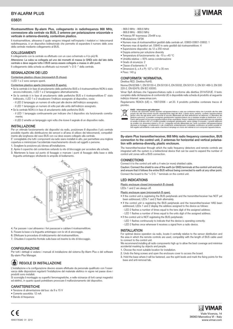
Energy Absorption QuadGuard cz User manual

QuadGuard®cz
Portable, Non-Gating, Redirective
Performance For Workzones
Installation Manual
Corporate Offices:
35 East Wacker Dr., 11th Floor
Chicago, IL 60601-2076
Telephone: (312) 467-6750
FAX: (312) 467-1356
http://www.energyabsorption.com/
Engineering and Manufacturing Facilities:
Rocklin, CA
Pell City, AL
A Quixote Company
Saving Lives By Design
ENERGY ABSORPTION
SYSTEMS, INC.

QuadGuard® cz
2
ImporImpor
ImporImpor
Important Intrtant Intr
tant Intrtant Intr
tant Introductoroductor
oductoroductor
oductory Notesy Notes
y Notesy Notes
y Notes
Proper installation of the QuadGuard cz is essential to as-
sure maximum performance. Take the time to review the
installation instructions and product limitations thoroughly
before performing the necessary work. Do not attempt to
install any crash cushion without the proper plans and
installation manual from the manufacturer.
If you need additional information, or have questions about
the QuadGuard cz, please call Energy Absorption Systems’
Customer Service Department at (888) 323-6374.
SS
SS
System Ovystem Ov
ystem Ovystem Ov
ystem Overer
erer
ervievie
vievie
vieww
ww
w
The QuadGuard cz is a highly efficient, redirective, non-
gating crash cushion for hazards ranging in width from
610 mm to 915 mm (2' to 3'). It consists of crushable,
energy-absorbing cartridges surrounded by a framework
of Quad-BeamTM panels.
The QuadGuard cz utilizes two types of cartridges in a
"staged" configuration to address both lighter cars and
heavier, high center-of-gravity vehicles. Its modular de-
sign allows the system length to be tailored to the design
speed of a site. Refer to the QuadGuard Product Manual
to determine the appropriate length system for a given
design speed.
Crash PCrash P
Crash PCrash P
Crash Perferf
erferf
erformanceormance
ormanceormance
ormance
The 6 bay QuadGuard cz has successfully passed the
NCHRP 350, Test Level 3 tests with both the light car and
pickup truck at speeds up to 100 km/h (62 mph) at angles
up to 20 degrees.
During head-on impacts, the QuadGuard cz telescopes rear-
ward and crushes to absorb the energy of impact. When
impacted from the side, it safely redirects the vehicle back
toward its original travel path and away from the hazard.
RETURN GOODS POLICY
Before returning any goods for credit please contact
Energy Absorption Systems Inc. Customer Service De-
partment at 1-888-323-6374 or your local distributor
for proper instructions.
Table of Contents
Important Introductory Notes ............................ 2
System Overview ............................................... 2
Crash Performance ............................................ 2
Installation ............................................... 3
Required Tools ................................................... 3
How to Determine Left/Right ............................. 5
Counting the Number of Bays ............................ 5
Measuring The Width ........................................ 6
Site Preparation/Foundation .............................. 6
QuadGuard cz Foundations ................................ 7
Bidirectional Sites .............................................. 7
Inspect Shipping ................................................ 8
Installation Procedures ...................................... 8
Transition Panel Types ....................................... 9
MP-3® Polyester Anchoring System ............... 30
Vertical Installations ........................................ 30
Horizontal Installations .................................... 31
MP-3® Installation Cautions ........................... 32
QuadGuard cz MP-3® Anchoring System ....... 33
Moving the System.................................... 34
QuadGuard cz (without Plate) .......................... 34
QuadGuard cz (with Plate) ............................... 36
QuadGuard cz (with Plate and Optional DPA
Anchorage) ...................................................... 38
Maintenance and Repair ............................. 40
Inspection Frequency....................................... 40
Visual Drive-By Inspection ............................... 40
Walk-Up Inspection ......................................... 40
Post-Impact Instructions ................................. 41
Parts Ordering Procedure ................................ 44
Limitations And Warnings ........................... 45

3
QuadGuard® cz
ReqReq
ReqReq
Requireduired
uireduired
uired
TT
TT
Toolsools
oolsools
ools
Documentation
• Manufacturer’s Installation Manual
• Manufacturer's Drawing Package
Cutting equipment
• Rebar Cutting Bit
• 22 mm (7/8") Concrete Drill Bits (*Two Fluted)
• Grinder, Hacksaw or Torch (optional)
•Drill Motor
•Drill Bits: 1/16" through 7/8"
* Energy Absorption Systems recommends using two
fluted drills to achieve optimum tensile strength when
installing the MP-3 anchoring system.
Hammers
• Roto Hammer
• Sledgehammer
•Standard Hammer
Wrenches
• Heavy Duty Impact Wrench
• Standard adjustable wrench
• 1/2
" drive sockets: 9/16", 11/16", 3/4", 15/16",
1 1/8", 1 1/4"
• Deep Sockets: 5/16", 1 1/4"
• Ratchet and attachments for the above sockets
•
Breaker Bar: 1/2
" x 24"
• Torque Wrench: 200 ft-lbs.
• Crescent Wrench: 300 mm [12"]
•Allen Wrench: 3/8"
•Impact Wrench:
1/2
"
Personal protective equipment
• Safety Glasses
• Gloves
Miscellaneous
• Traffic Control Equipment
• Lifting and Moving Equipment (A lifting device
is preferred although a forklift can be used.) Mini-
mum 5,000 lb. capacity required.
• Compressor (100 psi) and Generator (5 KW)
• Long Pry Bar
• Drift Pin 300 mm [12"]
•Center Punch
• Tape Measure 7.5 m (25')
• Chalk Line
•Concrete Marking Pencil
• Nylon bottle brush for cleaning 7/8" drilled holes
• Rags, Water, and Solvent for Touch-up
Note: The above list of tools is a general recommen-
dation. The actual number of tools required will
depend on specific site conditions and the com-
plexity of the installation.
InstallationInstallation
InstallationInstallation
Installation

QuadGuard® cz
4
Installation (cont’Installation (cont’
Installation (cont’Installation (cont’
Installation (cont’d.)d.)
d.)d.)
d.)
1 Cartridge
2 Diaphragm
3 Quad-Beam™ Fender Panel
Figure 1
4 Nose Cover
5 Monorail
6 Backup
6161
6161
610 mm [24"]0 mm [24"]
0 mm [24"]0 mm [24"]
0 mm [24"]
77
77
760 mm [30"]60 mm [30"]
60 mm [30"]60 mm [30"]
60 mm [30"]
9191
9191
915 mm [36"]5 mm [36"]
5 mm [36"]5 mm [36"]
5 mm [36"]
6767
6767
6740 mm [22'-1 3/8"]40 mm [22'-1 3/8"]
40 mm [22'-1 3/8"]40 mm [22'-1 3/8"]
40 mm [22'-1 3/8"]
Key
(Six bay systems shown)
Elevation
Plan

5
QuadGuard® cz
Figure 2
HoHo
HoHo
How to Determine Lefw to Determine Lef
w to Determine Lefw to Determine Lef
w to Determine Left/Rightt/Right
t/Rightt/Right
t/Right
To determine left from right when ordering parts, stand
in front of the system facing the hazard as shown in Fig-
ure 2. Your left is the system's left and your right is the
system's right.
Counting the Number of BaCounting the Number of Ba
Counting the Number of BaCounting the Number of Ba
Counting the Number of Baysys
ysys
ys
One bay consists of one cartridge, one diaphragm, and
two fender panels. The nose section is not considered a
bay, though there is a cartridge in the nose of each sys-
tem. Note that this means there will always be one more
cartridge in the system than the number of bays in the
system. To determine number of bays, count fender pan-
els on one side, see Figure 2 (5 bay system shown).
FRONT
RIGHT
LEFT
REAR
FENDER PANELS
NOSE
System Orientation
BAY
BAY
BAY
BAY
BAY
NOSE
CARTRIDGE
DIAPHRAGM
Installation (cont’Installation (cont’
Installation (cont’Installation (cont’
Installation (cont’d.)d.)
d.)d.)
d.)

QuadGuard® cz
6
Site PSite P
Site PSite P
Site Preparation/Freparation/F
reparation/Freparation/F
reparation/Foundationoundation
oundationoundation
oundation
Caution: The QuadGuard cz must be correctly
anchored for proper impact performance.
Anchor the system using one of the following:
7" studs may be used to anchor the system to 28 MPa
[4000 psi] min. P.C. concrete per the following mini-
mums:**
a) 150 mm [6"] non-reinforced roadway
b) 200 mm [8"] reinforced portable pad per draw-
ing 35-40-10
c) 180 mm [7"] deck structure
18" threaded rods may be used to install system on as-
phalt.**
**Refer to the QuadGuard cz MP-3 Anchoring System
Installation Instructions on page 31 for specifications.
Installation cross slope shall not exceed 8% and should
not vary (twist) more than 2% over the length of the sys-
tem; the pad surface shall have a light broom finish.
Note: Refer to pages 7 & 11 through 17 for an-
choring details.
Caution: Accurate placement of all steel rebar
is critical to avoid interference with the con-
crete Anchor Bolts.
WARNING!
Location of the backup in relation to nearby objects will
affect the operation of the attenuator. Upon impact, the
fender panels telescope toward and extend beyond the
rigid backup as much as 760 mm [30"] from their pre-
impact location. Position the backup so that the rear
ends of the last fender panels are a minimum of 760 mm
[30"] forward of objects that would otherwise interfere
with movement of the panels. Failure to comply with
this requirement may result in impaired system
performance offering motorists less protection and
cause component damage.
The nominal width of a system is the width between
side panels behind the backup (see Figure 3).
The outside width of the system is approximately
150 mm [6"] to 230 mm [9"] wider than the nominal
width. The width of the system is not the same as
the width of the backup.
BACKUP
Figure 3
Width of System
MeasuringMeasuring
MeasuringMeasuring
Measuring
TheThe
TheThe
The WidthWidth
WidthWidth
Width
The QuadGuard cz is available in three nominal widths:
• 610 mm [24"]
• 760 mm [30"]
• 915 mm [36"]
Installation (cont’Installation (cont’
Installation (cont’Installation (cont’
Installation (cont’d.)d.)
d.)d.)
d.)

7
QuadGuard® cz
QuadGuard cz FQuadGuard cz F
QuadGuard cz FQuadGuard cz F
QuadGuard cz Foundationsoundations
oundationsoundations
oundations
The QuadGuard cz may be installed on any of the following
Foundations using the specified anchorage:
Foundation A: Concrete Pad or Roadway
Foundation: 150 mm [6"] minimum depth
Portland Cement Concrete (P.C.C.)
Anchorage: MP-3® with 180 mm [7"] studs
140 mm [5.5"] embedment
Foundation B: Asphalt over P.C.C.
Foundation: 75 mm [3"] minimum Asphalt Concrete
(A.C.) over 75 mm [3"] minimum (P.C.C.)
Anchorage: MP-3 with 460 mm [18"] studs
420 mm [16.5"] embedment
Foundation C: Asphalt over Subbase
Foundation: 150 mm [6"] minimum (A.C.) over
150 mm [6"] minimum Compacted Sub-
base (C.S.)
Anchorage: MP-3 with 460 mm [18"] studs
420 mm [16.5"] embedment
Foundation D: Asphalt Only
Foundation: 200 mm [8"] minimum (A.C.)
Anchorage: MP-3 with 460 mm [18"] studs
420 mm [16.5"] embedment
Foundation Specifications
for Foundations A, B, C and D mentioned above
A. C. ( Asphalt Concrete )
AR-4000 A. C. (per ASTM D3381 '83) .75" Maximum,
Medium (Type A or B) aggregate
Sieve Size
Operating Range (%)Passing
1" 100
3/4" 95-100
3/8" 65-80
No. 4 49-54
No. 8 36-40
No. 30 18-21
No. 200 3-8
P.C.C. ( Portland Cement Concrete )
Stone aggregate concrete mix
4000 psi minimum compressive strength
(Sampling per ASTM C31-84 or ASTM C42-84a, test-
ing per ASTM C39-84)
C.S. ( Compacted Subbase )
150 mm [6"] minimum depth 95% compaction
Class 2 aggregate
Sieve Size Moving Average % Passing
3" 100
2 1/2" 90-100
No. 4 40-90
No. 200 0-25
Figure 4
PCMB Anchored To Roadway
Bidirectional SitesBidirectional Sites
Bidirectional SitesBidirectional Sites
Bidirectional Sites
At bidirectional sites, the rear of the system must be either
offset away from the traffic approaching from rear of the
system or be installed with a Transition Panel to prevent
snagging of vehicles (see Figure 45 on page 26 for maxi-
mum gap). The Transition Panels are depicted on page 9.
If attaching to portable concrete barrier (PCMB) the last sec-
tion of barrier must be anchored to the roadway (see Fig-
ure 4 and drawings supplied with your system). Anchor
Brackets are available from Energy Absorption Systems, Inc.
Note:
Walk-up inspections are recommended at least
once every six months for installations on asphalt.
Installation (cont’Installation (cont’
Installation (cont’Installation (cont’
Installation (cont’d.)d.)
d.)d.)
d.)

QuadGuard® cz
8
Inspect ShippingInspect Shipping
Inspect ShippingInspect Shipping
Inspect Shipping
Before installing the QuadGuard cz , check the received
parts against the shipping list supplied with the system.
Make sure all parts have been received.
Installation PInstallation P
Installation PInstallation P
Installation Prr
rr
roceduresocedures
oceduresocedures
ocedures
Note: The drawing package supplied with the
QuadGuard cz must be used with these instruc-
tions for proper assembly and should take prece-
dence over these general instructions.
QUAD-BEAM™ TO W-BEAM
TRANSITION PANEL
Figure 5
Transitioning the QuadGuard cz
Installation (cont’Installation (cont’
Installation (cont’Installation (cont’
Installation (cont’d.)d.)
d.)d.)
d.)
1) Determine Transition Type
A transition panel or side panel will be used on each
side of the backup. A side panel is not needed when a
transition panel is used. Several types of transitions
are available for use with the QuadGuard cz. Refer to
figures 5 through 10 and the drawing package to de-
termine which type of panels are being installed.

9
QuadGuard® cz
TT
TT
Transition Pransition P
ransition Pransition P
ransition Panelanel
anelanel
anel
TT
TT
Typesypes
ypesypes
ypes
Note: The proper transition or side panel must be
used for optimum impact performance of the sys-
tem. The correct panel to use will depend on the
direction of traffic and what type of barrier or haz-
ard the QuadGuard cz is shielding. Contact the
Customer Service Department prior to installation
if you have any questions.
Figure 8
Figure 9 Figure 10
Figure 7
Note: Wheel Deflectors may be required for this
application.
Figure 6
No Transition
Quad-Beam to Thrie-Beam Transition Panel
Quad-Beam to Safety Shape Barrier Transition Panel
Quad-Beam End Shoe Transition PanelQuad-Beam to W-Beam Transition Panel
Installation (cont’Installation (cont’
Installation (cont’Installation (cont’
Installation (cont’d.)d.)
d.)d.)
d.)

QuadGuard® cz
10
Bolting Monorail Segments Together
Figure 12
MONORAIL SEGMENT
MONORAIL SEGMENT
3) Bolt together monorail segments
All monorail segments must be bolted together us-
ing the bolts provided with the QuadGuard cz. The
number of monorail segments will vary by system
length. Torque the nut until the lock washer is fully
compressed. Refer to Figure 12.
QuadGuard cz (without plate)QuadGuard cz (without plate)
QuadGuard cz (without plate)QuadGuard cz (without plate)
QuadGuard cz (without plate)
2) Mark System Location
Locate the centerline of the system by measuring the
proper offset from the hazard. Refer to the drawing
package supplied with the system. Place chalk line
to mark the centerline of the system. Mark a con-
struction line parallel to the center line and offset
165 mm [6.5"] to one side as shown in Figure 11.
The edge of the monorail will be placed on this line.
Note: The concrete pad should be installed per the
project plans supplied with the system.
Figure 11
(Top View of Concrete Pad)
Locating Construction Line
165 mm [6.5"]
CENTERLINE OF SYSTEM
CONSTRUCTION LINE
WARNING!
Location of system with respect to the hazard is
critical and dependent on the type of transition
panel used. See the project plans supplied with the
system for details.
5/8" X 3 1/2"
G5 HEX BOLT
5/8" LOCK WASHER
5/8" HEX NUT
Installation (cont’Installation (cont’
Installation (cont’Installation (cont’
Installation (cont’d.)d.)
d.)d.)
d.)

11
QuadGuard® cz
4) Anchor the Backup and Monorail
Refer to Figure 13 (showing backup assembly) and
figures 14 and 15 (showing monorail installation).
Also refer to the drawing package.
A. Backup Installation
Locate backup and monorail on foundation with side
of monorail on the construction line (see Figure 15).
Verify that any applicable transition panels fit prop-
erly before anchoring backup. Drill anchor holes in
foundation using the backup as template. Anchor the
backup to the foundation using the MP-3 vertical kits
provided.
See page 12 for anchoring options and page 28 “MP-3
Polyester Anchoring System".
B. Monorail installation
Locate the monorail using the monorail assembly
drawings. Orient monorail so that the monorail
tongues face the backup. Drill anchor holes using
the monorail as a template (see figure 15). Do not
drill through pad. Anchor each monorail section us-
ing the MP-3 vertical kits provided. Refer to Figure 17
and the MP-3 Polyester Anchoring System Instruc-
tions on page 28. It is important to install each seg-
ment of monorail in alignment from the back to the
front of the system (+/- 6 mm [1/4"]).
CZ BACKUP
Figure 13
Anchoring cz Backup to Foundation
WARNING!
Every hole and slot in backup and monorail must have
an MP-3 stud anchoring it.
Figure 15
Backup and Monorail Location
100 mm [4"] BACKUP MONORAIL 3/4" STUD
CENTERLINE
CONSTRUCTION LINE
CAUTION:
40 mm [1.50"]
MAX. STUD HEIGHT
Figure 14
MP-3 ANCHOR
BACKUP OR MONORAIL
ROADWAY
WARNING!
Improper alignment at the monorail splice joints will
prevent proper system collapse during an impact.
Proper Stud Height
VERTICAL MP-3 KIT
WITH 3/4" X 7" STUD
Installation (cont’Installation (cont’
Installation (cont’Installation (cont’
Installation (cont’d.)d.)
d.)d.)
d.)

QuadGuard® cz
12
QuadGuard cz (without plate)QuadGuard cz (without plate)
QuadGuard cz (without plate)QuadGuard cz (without plate)
QuadGuard cz (without plate)
Note: Cross slope shall not exceed 8% and not
vary (twist) more than 2% from front to back.
See Figure 16.
8% SLOPE
MAX.
Figure 16
Max. Allowable Cross Slope
Figure 17
Anchoring the System
SOIL
3/4" DIA. MP-3
THREADED ROD SYSTEM
QUADGUARD CZ SYSTEM
MIN. 483mm [19"] TYP.
ROADWAY EDGE
C - ASPHALT* ROADWAY
D - NON-REINFORCED P.C. CONCRETE* ROADWAY
OR E - COMPACTED SUBBASE*
*MATERIALS:
C - ASPHALTIC CONCRETE
•ASPHALT BINDER AR-4000
•ASPHALT AGGREGATE 3/4
(19mm) MAX. MED A B
D - 28 MPa [4000 PSI] P.C. CONCRETE
E - SUBBASE PREPARED AS COMPACTED
•CLASS 2
•95% COMPACTION MIN. LAYER
Note:
Walk-up inspections are recommended at least
once every six months for installations on as
phalt.
Note: 18"Anchors are supplied with the QuadGuard cz.
If another substrate is encountered, please call Customer
Service to discuss options.
Use MP-3 Polyester Anchoring System supplied by
Energy Absorption Systems, Inc. or approved equal.
QuadGuard czs installed on asphalt must be inspected
to ensure the anchors are still properly set following
each impact. Re-anchor as necessary.
Use the Plate/Monorail sections as a template to drill
anchor holes. Refer to figure 17 and instructions con-
tained in the MP-3 Polyester Anchor box supplied with
the system for detailed anchoring instructions.
Depth Combinations
Req’d Stud LengthEDC
180 mm [7"]--150 mm [6"]--
460 mm [18"]--75 mm [3"]75 mm [3"]
--
----
150 mm [6"] 460 mm [18"]
460 mm [18"]
150 mm [6"]
200 mm [8"]
Installation (cont’Installation (cont’
Installation (cont’Installation (cont’
Installation (cont’d.)d.)
d.)d.)
d.)

13
QuadGuard® cz
PLATE/MONORAIL SEGMENT
Bolting Plate/Monorail Segments Together
Figure 18
PLATE/MONORAIL SEGMENT
Detail 18a
3/4" X 10 UNC STUD
18A
QuadGuard cz (with plate)QuadGuard cz (with plate)
QuadGuard cz (with plate)QuadGuard cz (with plate)
QuadGuard cz (with plate)
2) Mark System Location
Locate the centerline of the system by measuring the
proper offset from the hazard. Refer to the drawing pack-
age supplied with the system. Place chalk line to mark
the centerline of the system. Mark a construction line
parallel to the center line and offset 534 mm [21"] to
one side. The edge of the monorail plate will be placed
on this line. See figure 19.
3) Bolting together of plate/monorail seg-
ments
All plate/monorail segments must be bolted together
using the bolts provided with the QuadGuard cz. The
number of monorail segments will vary by system
length. Torque the nut until the lock washer is fully
compressed. Refer to Figure 18.
Figure 19
534 mm [21”]
CONSTRUCTION LINE
CENTERLINE
5/8" X 3 1/2" G5 HEX BOLT
5/8" LOCK WASHER
5/8" HEX NUT
Installation (cont’Installation (cont’
Installation (cont’Installation (cont’
Installation (cont’d.)d.)
d.)d.)
d.)

QuadGuard® cz
14
QuadGuard cz (with plate)QuadGuard cz (with plate)
QuadGuard cz (with plate)QuadGuard cz (with plate)
QuadGuard cz (with plate)
4) Anchor the System
Note: Cross slope of plate shall not exceed 8% and
not vary (twist) more than 2% from front to back.
For these conditions, a leveling pad is required.
See Figure 20.
8% SLOPE
MAX.
Figure 20
Max. Allowable Cross Slope
Figure 21
Anchoring the System
SOIL
3/4" DIA. MP-3
THREADED ROD SYSTEM
QUADGUARD CZ SYSTEM
MIN. 483mm [19"] TYP.
ROADWAY EDGE
C - ASPHALT*
D - REINFORCED P.C. CONCRETE*
OR E - COMPACTED SUBBASE*
*MATERIALS:
C - ASPHALTIC CONCRETE
•ASPHALT BINDER AR-4000
•ASPHALT AGGREGATE 3/4
(19mm) MAX. MED A B
D - 28 MPa [4000 PSI] P.C. CONCRETE
E - SUBBASE PREPARED AS COMPACTED
•CLASS 2
•95% COMPACTION MIN. LAYER
Depth Combinations
Note:
Walk-up inspections are recommended at least
once every six months for installations on as
phalt.
Note: 18"Anchors are supplied with the QuadGuard cz.
If another substrate is encountered, please call Customer
Service to discuss options.
Req’d Stud LengthEDC
180 mm [7"]--150 mm [6"]--
460 mm [18"]--75 mm [3"]75 mm [3"]
--
----
150 mm [6"] 460 mm [18"]
460 mm [18"]
Installation (cont’Installation (cont’
Installation (cont’Installation (cont’
Installation (cont’d.)d.)
d.)d.)
d.)
Use MP-3 Polyester Anchoring System supplied by
Energy Absorption Systems, Inc. or approved equal.
QuadGuard czs installed on asphalt must be inspected
to ensure the anchors are still properly set following
each impact. Re-anchor as necessary.
Use the Plate/Monorail sections as a template to drill
anchor holes. Refer to figure 21 and instructions con-
tained in the MP-3 Polyester Anchor box supplied with
the system for detailed anchoring instructions.
150 mm [6"]
200 mm [8"]

15
QuadGuard® cz
QuadGuard cz (with plate andQuadGuard cz (with plate and
QuadGuard cz (with plate andQuadGuard cz (with plate and
QuadGuard cz (with plate and
Optional DPOptional DP
Optional DPOptional DP
Optional DPAA
AA
A AncAnc
AncAnc
Anchorage)horage)
horage)horage)
horage)
2) Mark System Location
Locate the centerline of the system by measuring the
proper offset from the hazard. Refer to the drawing pack-
age supplied with the system. Place chalk line to mark
the centerline of the system. Mark a construction line
parallel to the center line and offset 534 mm [21"] to
one side. The edge of the monorail plate will be placed
on this line. See figure 22.
WARNING!
Location of the system with respect to the hazard
is critical and dependent on the type of transition
panel used. See the project plans supplied with the
system for details.
3a)
Bolting together of plate/monorail segments
All plate/monorail segments must be bolted together
using the bolts provided with the QuadGuard cz. The
number of monorail segments will vary by system
length. Torque the nut until the lock washer is fully com-
pressed. Refer to Figure 18.
WARNING!
All QuadGuard cz plate/monorail segments must be
bolted together and torqued to fully compress the lock
washer before attempting to move or install the system.
Figure 22
534 mm [21”]
CONSTRUCTION LINE
CENTERLINE
Installation (cont’Installation (cont’
Installation (cont’Installation (cont’
Installation (cont’d.)d.)
d.)d.)
d.)

QuadGuard® cz
16
QuadGuard cz (with plate andQuadGuard cz (with plate and
QuadGuard cz (with plate andQuadGuard cz (with plate and
QuadGuard cz (with plate and
Optional DPOptional DP
Optional DPOptional DP
Optional DPAA
AA
A AncAnc
AncAnc
Anchorage)horage)
horage)horage)
horage)
3b) Bolting together of Wing Plates to
Monorail Plate Segments
After the monorail plate segments have been bolted
together, place the system on top of several saw
horses or other type of adequate table support. Us-
ing 5/8" x 2" rail bolts and 5/8" rail nuts, attach a wing
plate to the front of the first monorail plate, to the
rear of the backup monorail plate, and at the con-
nection point for each monorail plate segment. See
figure 23.
Figure 23
Wing Plate Attachment
FIRST MONORAIL PLATE
WING PLATE
BACKUP MONORAIL PLATE
5/8” X 2" RAIL BOLT
5/8” RAIL NUT
Installation (cont’Installation (cont’
Installation (cont’Installation (cont’
Installation (cont’d.)d.)
d.)d.)
d.)

17
QuadGuard® cz
WARNING!
Location of the system with respect to the hazard
is critical and dependent on the type of transition
panel used. See the project plans supplied with the
system for details.
4) Anchor the System
Note: The plate is not to be used on cross slopes
that exceed 8% or vary (twist) more than 2% from
front to back. For these conditions, a leveling pad
is required. See Figure 24.
Use the parts supplied by Energy Absorption Systems, Inc.
QuadGuard czs installed on asphalt or soil must be in-
spected to ensure the system is properly anchored fol-
lowing each impact. Refurbish and re-anchor as nec-
essary.
1. Lift the system into place at the marked loca-
tion. If required, attach the system to the haz-
ard/barrier via pin and loop connection (see Fig-
ure 25) and/or transition panel(s).
8% SLOPE
MAX.
Figure 24
Max. Allowable Cross Slope
Figure 25
Pin and Loop Connection
2. Once system is in place, position pile driving
equipment over a square hole in the outboard
wing plate as shown in Figure 26.
3. Place the 72 ¾" x 6" x 6" Drivable Post into the
square hole in the wing plate as shown in Fig-
ure 26. Use a small level to ensure the post is
straight for pile driving. Drive post into the ground
until the post's top plate is flush with the top of
the wing plate.
4. Use the ¾" x 2 ½" hex bolts to fasten the ¾" x 10"
x 10" Post Cap to the top of the post as shown in
Figure 27.
Figure 26
Figure 27
POST CAP
DRIVABLE POST
Repeat this procedure until system is completely an-
chored. 3/4" X 2 1/2" G8
HEX BOLT
DRIVABLE POST
WING PLATE
Installation (cont’Installation (cont’
Installation (cont’Installation (cont’
Installation (cont’d.)d.)
d.)d.)
d.)

QuadGuard® cz
18
5) Attach Side Panels and/or Transition
Panels to Backup Assembly
Attach the side panel or transition panel as appropri-
ate to each side of backup. Refer to Figure 28 and
the drawing package for more information.
Figure 28
Side Panel/Transition Panel Attachment
5/8" RAIL NUT
(SEE FIGURE 32)
SIDE PANELS SHOWN.
IN SOME CASES, THIS WILL
BE A TRANSITION PANEL
(SEE FIGURES 7 THRU 10)
CZ BACKUP
5/8" X 2" RAIL BOLT
Installation tip:
Use drift pin to align the center hole of the panel with
the center hole of the backup before installing the
rail bolts.
Note: A side panel is not needed when a transition
panel is used.
Installation (cont’Installation (cont’
Installation (cont’Installation (cont’
Installation (cont’d.)d.)
d.)d.)
d.)

19
QuadGuard® cz
6) Attach Monorail Guides
Using 3/4" x 2" Grade 8 Hex Bolts, 3/4" Lock Washers
and 3/4" Nuts, attach monorail guides to diaphragms
as shown in Figure 29.
Figure 29
DIAPHRAGM
Figure 31
Diaphragm spacing
915 mm [36"] DIAPHRAGMS
915 mm [36"]
TYPICAL
7) Install Diaphragms
Orient a diaphragm so that the front face of the
Quad-Beam shape faces toward the nose of the sys-
tem as shown in Figure 30. Slide one diaphragm all
the way to the backup to ensure the system is able to
collapse properly during impact. Once this has been
verified, slide the diaphragm forward to approximately
915 mm [36"] in front of the backup. Orient and slide
all other diaphragms onto monorail and position each
approximately as shown in Figure 31.
TOWARD NOSE
FRONT
BACK
Figure 30
Diaphragm Orientation
QUAD-BEAM
FRONT FACE OF BACKUP MONORAIL
Monorail Guide Attachment
3/4" HEX NUT
3/4" LOCK WASHER
3/4" X 2” G8 HEX BOLT
MONORAIL GUIDE
Installation (cont’Installation (cont’
Installation (cont’Installation (cont’
Installation (cont’d.)d.)
d.)d.)
d.)

QuadGuard® cz
20
8) Install Fender Panels
Note: Do not mix the 5/8" rail nuts (large) with
the 5/8" hex nuts (small). See Figure 32.
32 mm [1.25"] 24 mm [0.94"]
Figure 32
Rail Nuts are Oversize
5/8" RAIL NUT (LARGE) 5/8" HEX NUT (SMALL)
Figure 33
Fender Panel Assembly
DIAPHRAGM
BACKUP OR DIAPHRAGM
5/8" RAIL BOLT
5/8" FLATHEAD
SOCKET SCREW
MUSHROOM WASHER
FENDER PANEL
SIDE PANEL,
FENDER PANEL, OR
TRANSITION PANEL
KEEP CENTER HOLE EMPTY
FOR NEXT PANEL
SPRING
5/8" FLAT WASHER
5/8" RAIL NUT (LARGE)
5/8" RAIL BOLT
Starting at the backup, install left and right fender
panels as shown in Figures 33, 34 and fender panel
assembly drawing.
Step 1
Place the fender panel so that the center hole of
the rearward diaphragm is lined up with the ap-
proximate center of the slot in the fender panel.
Attach mushroom washer assembly as shown in
Figures 33 and 34, but do not torque at this time.
(This helps to balance the fender panel.)
Step 2
Slide the fender panel forward until the holes in
the fender panel line up with the holes in the for-
ward diaphragm.
Step 3
Use a drift pin to align the
center hole of the fender
panel with the center hole
of the diaphragm.
Step 4
Attach the front of the
fender panels to the next
diaphragm using two rail
bolts and large hex nuts
per side. Use only the top
and bottom holes, leave
the center hole open un-
til the next fender panel
is installed.
5/8" HEX NUT (SMALL)
5/8" RAIL NUT (LARGE)
Installation (cont’Installation (cont’
Installation (cont’Installation (cont’
Installation (cont’d.)d.)
d.)d.)
d.)
Table of contents
