Energy Recovery Pressure Exchanger 65 Series Instruction manual

ENERGY RECOVERY
,
INC.
INSTALLATION, OPERATION, & MAINTENANCE
MANUAL
ERI DOCUMENT NUMBER 80023-01 REVISION 1
ERI™
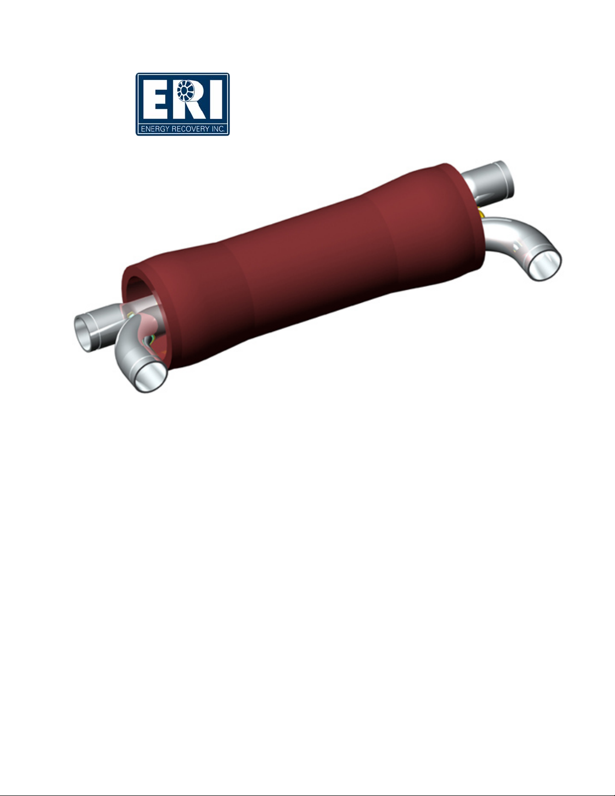
65 Series Pressure Exchanger™
Energy Recovery Device
for Brackish Water Systems
Energy Recovery, Inc.™
1908 Doolittle Drive, San Leandro, CA 94577 USA
Tel: +1 510 483 7370 / Fax: +1 510 483 7371
© ENERGY RECOVERY, INC., 2006

TABLE OF CONTENTS
1.0 INTRODUCTION 1
2.0 SAFETY 1
3.0 QUALITY & ARRIVAL INSPECTION 2
4.0 DESIGN CONSIDERATIONS 2
4.1 How the PX Energy Recovery Device Works 2
4.2 PX Energy Recovery Devices in BWRO Systems 3
4.3 PX Energy Recovery Device Performance 4
4.4 The PX Booster Pump 5
4.5 Control of Feed Flow, Pressure, and Water Quality 5
4.6 Fresh Water Flushing 6
4.7 Debris and Initial Flushing 6
4.8 High Pressure Remains After Shutdown 6
4.9 Low Pressure Isolation and Over pressurization 6
4.10 Multiple PX Unit Manifold Design 6
5.0 INSTALLATION 7
6.0 OPERATION 8
6.1 System Performance Specifications, Precautions, and Conditions 8
6.2 Start and Stop Procedures 10
6.3 Flow Control and System Balancing 12
7.0 SPARE PARTS AND TOOL KITS 14
8.0 MAINTENANCE 15
8.1 Disassembly Procedure 16
8.2 Assembly Procedure 20
9.0 TROUBLESHOOTING 26
10.0 FIELD COMMISSIONING 29
11.0 REVISION LOG 29
12.0 WARRANTY & LIABILITY 30
13.0 DRAWINGS AND DATA 31

BRACKISH 65-SERIES PRESSURE EXCHANGER ENERGY RECOVERY DEVICES
___________________________________________________________
Energy Recovery, Inc. ERI Document Number 80023-01-01
1
NOTE
CAUTION
These flags denote items that, if not strictly observed, can
result in serious injury to personnel.
These flags denote items that, if not strictly observed, can
result in damage or destruction to equipment.
These flags denote highlighted items.
1.0 INTRODUCTION
This manual contains instructions for the installation, operation, and maintenance of the Energy
Recovery, Inc.™™ERI™Brackish 65 Series PX Pressure Exchanger™energy recovery device in
brackish reverse osmosis (BWRO) systems. This information is provided to ensure the long life
and safe operation of your PX™energy recovery device. Please read this manual thoroughly
before installation and operation, and keep it for future reference. This manual is intended for use
by personnel with training and experience in the operation and maintenance of fluid handling
systems.
2.0 SAFETY
The PX Pressure Exchanger energy recovery device is designed to provide safe and reliable
service. However, it is both a pressure vessel and a rotating industrial machine. Operations and
maintenance personnel must exercise prudence and proper safety practices to prevent injury and
to avoid damaging the equipment and surrounding areas. Use of this manual does not relieve
operation and maintenance personnel of the responsibility of applying normal good judgment in
the operation and care of this product and its components. The safety officer at the location
where this equipment is installed must implement a safety program based on a thorough analysis
of local industrial hazards. Proper installation and care of shutdown devices and over-pressure
and over-flow protection equipment must be an essential part of any such program. In general,
all personnel must be guided by all the basic rules of safety associated with high-pressure
equipment and processes. Operation under conditions outside of those stated in Table 6.1 is
unsafe and can result in damage to the Energy Recovery, Inc. (ERI) device.
The flags shown and defined below are used throughout this manual. They should be given
special attention when they appear in the text.
™Energy Recovery, Inc., ERI, PX, Pressure Exchanger, PX Pressure Exchanger and the ERI logo
are trademarks of Energy Recovery, Inc.

BRACKISH 65-SERIES PRESSURE EXCHANGER ENERGY RECOVERY DEVICES
___________________________________________________________
Energy Recovery, Inc. ERI Document Number 80023-01-01
2
Energy Recovery, Inc. will not be liable for any project delay, damage or
injury caused by the failure to comply with the procedures in this manual.
This product must never be operated at flow rates, pressures or temperatures
outside of those stated in Table 6.1, or used with liquids not approved by
Energy Recovery, Inc.
NOTE
3.0 QUALITY & ARRIVAL INSPECTION
Energy Recovery, Inc.’s commitment to quality includes the procurement of top quality materials
and fabrication to extremely tight tolerances. At each stage of the manufacturing process, every
part is checked to ensure it meets all dimensional specifications. Assembled ERI devices are
subjected to extensive testing in our wet test facility. Each PX unit is tested for efficiency, noise
levels, operating pressures, and flow rates. Testing records are maintained and each unit is
tracked with a serial number. Each PX unit should be inspected immediately upon arrival at a
customer’s site and any irregularities due to shipment should be reported to the carrier. PX
Pressure Exchanger devices are packed in polystyrene foam with plugs in the fittings to protect
the unit from damage during transport. The PX unit has been run with a dilute biocide solution to
minimize the possibility of biological growth during shipment and storage. The PX unit must
never be exposed to temperatures below 33 degrees Fahrenheit (deg F) [1 deg Centigrade (C)] or
above 113 deg F [45 deg C] during storage or operation.
4.0 DESIGN CONSIDERATIONS
4.1 How the PX Energy Recovery Device Works
The PX Pressure Exchanger energy recovery device facilitates pressure transfer from the high-
pressure brine reject stream to the low-pressure feedwater feed stream. It does this by putting the
streams in direct, momentary contact that takes place in the ducts of a rotor. The rotor is fit into a
ceramic sleeve between two ceramic end covers with precise clearances that, when filled with
high-pressure water, create an almost frictionless hydrodynamic bearing. At any given instant,
half of the rotor ducts are exposed to the high-pressure stream and half to the low-pressure
stream. As the rotor turns, the ducts pass a sealing area that separates high and low pressure.
Thus, the ducts that contain high pressure are separated from the adjacent ducts containing low
pressure by the seal that is formed with the rotor’s ribs and the ceramic end covers.
A schematic representation of the ceramic components of the PX energy recovery device is
provided in Figure 4-1. Feedwater supplied by the feedwater supply pump flows into a rotor duct
on the left side at low pressure. This flow expels brine from the duct on the right side. After the
rotor turns past a sealing area, high-pressure brine flows into the right side of the duct,
compressing and expelling the feedwater. Pressurized feedwater then flows out to the booster
pump. This pressure exchange process is repeated for each duct with every rotation of the rotor,
so that the ducts are continuously filling and discharging. At a nominal speed of 1,200 rpm, 20
revolutions are completed every second.

BRACKISH 65-SERIES PRESSURE EXCHANGER ENERGY RECOVERY DEVICES
___________________________________________________________
Energy Recovery, Inc. ERI Document Number 80023-01-01
3
Figure 4-2 illustrates the typical flow path of a PX energy recovery device in a BWRO system.
The reject brine from the BWRO membranes (G) passes through the PX unit, where its pressure
is transferred directly to a portion of the incoming raw feedwater at up to 97% efficiency. This
pressurized feedwater stream (D), which is nearly equal in volume and pressure to the reject
stream, passes through a booster pump (not the main high-pressure pump) to add the small
amount of pressure lost to friction in the PX unit, the membranes, and the associated piping. The
booster pump also serves to drive the flow of the high-pressure stream through the PX unit (G
and D). Fully pressurized feedwater then merges with the main feedwater to the BWRO system
after the main high-pressure pump.
4.2 PX Energy Recovery Devices in BWRO Systems
The PX energy recovery device fundamentally changes the way a BWRO system operates. The
issues presented in this and the following sections should be taken into consideration when
designing a BWRO system. In addition, engineers at Energy Recovery, Inc. are available for
design consultation and review of process and instrument diagrams.
Figure 4-1. Flow Path through PX Unit
Table 4-1. Example Flow Rates and Pressures
High Pressure side
Sealed Area
High-pressure feedwater
going to booster pump
High-
p
ressure brine reject
from RO membranes
Low-pressure
feedwater inlet
Low-pressure brine
reject to drain
Feedwater
Brine
Interface
Rotor Rotation
Low Pressure side
Figure 4-2. Typical Flow Path of a BWRO System with a PX Unit
Inter-stage
Boost Pump
Main High
Pressure Pump
Feedwater Supply
Pump
Fresh Water
Pressure Exchanger
Device or PX Array
F
H
G
I
E
B
A
C
D
J

BRACKISH 65-SERIES PRESSURE EXCHANGER ENERGY RECOVERY DEVICES
___________________________________________________________
Energy Recovery, Inc. ERI Document Number 80023-01-01
4
The flow rate, pressure, and quality of the feed streams to the PX unit must be monitored and
controlled. Operation and control of a PX unit in a BWRO system can be understood by
visualizing two parallel pipes, one with high-pressure water and one with low-pressure water
flowing through the PX unit. With reference to Figure 4-1, the high-pressure water flows in a
circuit through the membranes, the PX unit or PX unit array, the booster pump, and back to the
membranes (F→G→D→E) at a rate controlled by the booster pump with a variable frequency
drive or a throttle valve at the booster pump discharge. The low-pressure water flows from the
feedwater supply pump through the PX unit or PX unit array to the system discharge (A→B→H)
at a rate controlled by the supply pump and a throttle valve in the brine discharge from the PX
unit or PX unit array (H). Since the high- and low-pressure flows are independent, the BWRO
plant must be designed for monitoring and control of the flow rates of both streams.
Example flow rates and pressures for a BWRO system with one PX-220B are listed in Table 4.1
below, with reference to Figure 4-2. In a BWRO system with an ERI energy recovery device
installed, the main high-pressure (HP) pump is sized to equal the BWRO permeate flow plus a
small amount of bearing lubrication flow, not the full BWRO feed flow.
4.3 PX Energy Recovery Device Performance
PX Pressure Exchanger device performance data for a range of possible flow and pressure
conditions is provided on Energy Recovery, Inc.’s Website. The following data are given in the
form of performance curves:
•High- and low-pressure pressure drop as a function of flow rate
•Volumetric mixing as a function of flow rate
•Noise as a function of flow rate
•Lubrication flow as a function of pressure
Table 4.1. Typical BWRO System Flows and Pressures
Stream Description Flow Rate
gpm / m3/hr Pressure
psi / bar
A Feedwater Supply 2000 / 455 18 / 1.2
B PX LP IN / Feedwater 490 / 111 18 / 1.2
C Main HP Pump outlet 1510 / 343 175 / 12
D PX HP OUT / Feedwater 490 / 111 175 / 12
E RO Feed Stream 2000 / 455 175 / 12
F First Stage Reject 1000 / 227 155 / 11
G Second Stage Feed 1000 / 227 210 / 14
H PX HP IN / Second Stage Reject 500 / 114 190 / 13
I PX LP OUT / Second Stage Reject 500 / 114 8 / 0.6
J RO System Permeate 1500 / 341 -

BRACKISH 65-SERIES PRESSURE EXCHANGER ENERGY RECOVERY DEVICES
___________________________________________________________
Energy Recovery, Inc. ERI Document Number 80023-01-01
5
Do not exceed the maximum allowable feed flow rate to the PX
unit. This may damage the PX device.
4.4 The PX Booster Pump
In the typical BWRO system illustrated in Figure 4-2, a booster pump is required to add pressure
to the feedwater from the PX unit before it merges with the high-pressure feed to the second
stage membranes. A pressure boost is necessary to compensate for friction losses in the first
stage membranes, the PX unit, and the associated piping. The flow and pressure supplied by the
booster pump must be controlled with a variable frequency drive or control valve because the
booster pump controls the high-pressure flow rate through the PX unit. Recommended practice is
to use a slightly oversized booster pump to handle projected reverse osmosis (RO) membrane
flows, taking into account seasonal variations, membrane fouling, and manifold losses. Energy
Recovery, Inc. carries a line of PX Booster Pumps with capacities up to 300 gpm (68 m3/hr). ERI
PX Booster Pumps can be manifolded to run in parallel to achieve higher capacities. Alternately,
several suppliers of high-capacity booster pumps are listed on Energy Recovery, Inc.’s Website.
4.5 Control of Feed Flow, Pressure, and Water Quality
Special consideration should be given to flow and pressure control of the feedwater supply. As
mentioned, a throttle valve in the brine discharge from the PX unit can be used to control low-
pressure flow through the PX unit(s). Once this valve is set, flow will remain constant as long as
the feed pressure does not change. However, if the feed pressure changes, the low-pressure (LP)
flow through the PX unit will change accordingly. As long as the maximum allowable feed flow
to the PX unit is never exceeded, the PX unit will automatically adjust to small pressure and flow
variations. Momentary feed pressure increases can result in flow spikes that could overflow and
damage the PX unit.
Pressure/flow spikes require particular consideration in systems with multiple BWRO trains as
trains go on- and off-line. An automatic flow control system is not typically responsive enough
to provide constant flow during sudden pressure changes. Emergency shutdown sequences
should include shutting down the feedwater supply pump(s) to avoid overflow. If large low-
pressure spikes and overflow cannot be avoided, a pressure regulator and/or relief valve should
be installed upstream of the PX units to help stabilize flow. Where feasible, Energy Recovery,
Inc. recommends incorporation of a high-flow alarm on the feedwater supply set at 95% of PX
unit capacity and an automatic high flow shutdown at a maximum of 100% of capacity.
Air in the feed streams to the PX unit can damage the device. All air must be purged from both
the low- and high-pressure circuits before the system is BWRO pressurized. If the BWRO
system will be started automatically, allow sufficient time in the startup sequence so that air may
be purged from the system before the HP pump is started.
CAUTIONCAUTION

BRACKISH 65-SERIES PRESSURE EXCHANGER ENERGY RECOVERY DEVICES
___________________________________________________________
Energy Recovery, Inc. ERI Document Number 80023-01-01
6
NOTE
Failing to flush the PX unit with fresh water before shutdowns
may result in excessive biological growth that may foul the PX
unit and inhibit rotation upon start-up.
CAUTION
4.6 Fresh Water Flushing
The BWRO system should include provisions for flushing the PX energy recovery device with
fresh water. Flushing is necessary to prevent biological growth in the PX unit during prolonged
shutdowns. Biological growth can cause the PX unit’s rotor to stick upon start-up. See Section
6.2 for detailed startup and shutdown procedures.
4.7 Debris and Initial Flushing
Prior to initial start up, all piping associated with the PX energy recovery device should be
thoroughly flushed to assure that no debris enters and/or damages the PX unit. Energy Recovery
recommends installation of basket strainers at both inlets to the PX device or PX device array.
Basket strainers protect the PX unit(s) from damage caused by debris coming from upstream
failures that sometimes occur as a result of corrosion, worn parts, or filter failures. As an
alternative, ERI recommends installation of temporary startup strainers during startup and
commissioning activities. ERI can provide a list of strainer vendors upon request.
4.8 High Pressure Remains After Shutdown
The high-pressure section of a BWRO system with a PX energy recovery device can remain
pressurized for a long time after shutdown. Pressure decreases as water flows through the
hydrodynamic bearing of the PX unit. If more rapid system depressurization during shutdowns is
required, the system should be designed with accommodating valves and piping.
4.9 Low Pressure Isolation and Over pressurization
If the low-pressure flow stream of the PX energy recovery device is isolated before the high-
pressure side is depressurized, there is a risk that the PX unit or the low-pressure piping could be
damaged by over-pressurization. High-pressure water continuously flows through the PX
device’s hydrodynamic bearing to low-pressure regions in the PX unit. To prevent this over-
pressurization scenario, appropriate relief valves should be used and procedures implemented to
assure that the high-pressure side of the PX unit is depressurized prior to isolation of the low-
pressure side.
4.10 Multiple PX Unit Manifold Design
The performance of PX energy recovery devices in arrays is identical to the performance of
individual PX units as long as the manifolds are correctly designed. Even flow distribution in a
If rapid depressurization is desired, a high-pressure bypass valve can be
installed at the outlet of the RO membranes, which can be used to manually
and/or automatically relieve the pressure at shutdowns.

BRACKISH 65-SERIES PRESSURE EXCHANGER ENERGY RECOVERY DEVICES
___________________________________________________________
Energy Recovery, Inc. ERI Document Number 80023-01-01
7
Figure 4-4 – Double Coupling Connections for Large Manifolds
ERI encourages plant designers and engineers to submit
P&IDs to ERI for engineering review, especially for large or
complex BWRO systems.
PX unit array can be achieved by using large manifold pipe diameters eliminate manifold
constrictions.. In a sufficiently large manifold, the pressure drop along the manifold is much less
than the pressure drop through a PX unit such that the manifolds serve as constant-pressure
reservoirs, regardless of flow orientation. In general, a pressure drop of 1 psi (0.07 bar) or less
along the length of the manifold will provide even flow distribution. With a properly designed
manifold, the PX units in an array naturally distribute flow evenly.
A sample connection at the low-pressure outlet of each PX unit in a PX unit array can be used to
confirm the performance of individual units. Low-pressure sample ports are recommended over
high-pressure sample ports because low-cost, corrosion-resistant plastic valves can be used.
When PX devices are operating normally at balanced flow, the salinity of the low-pressure outlet
water from each PX unit will be approximately equal to the salinity of the reject water from the
membranes. If the PX units are not balanced, the salinity of the low-pressure discharge from the
unit will be much lower than the salinity of the reject water from the membranes. If one of the
PX units is not functioning properly, the salinity of the low-pressure discharge from the unit will
be lower than that of the other units. If a rotor is stuck, the salinity from the stuck unit will be
close to the salinity of the feedwater feed.
For systems with large manifolds, double flexible coupling connections should be considered to
facilitate alignment of the PX units. These connections are illustrated in Figure 4-4.
5.0 INSTALLATION
The 65 Series Pressure Exchanger has four connections labeled HP IN, HP OUT, LP IN, and LP
OUT.
NOTE

BRACKISH 65-SERIES PRESSURE EXCHANGER ENERGY RECOVERY DEVICES
___________________________________________________________
Energy Recovery, Inc. ERI Document Number 80023-01-01
8
Thoroughly flush associated piping with water filtered to 10
microns before installing the PX unit. Foreign material may cause
damage.
The PX unit must not be supported by its pipe fittings, nor should
the PX unit be allowed to support piping or manifolds. During
installation do not lift the PX by the ports.
Do not allow the high-pressure reject feed to the PX unit to exceed
400 psi (28 bar). If necessary, install a pressure switch and/or
safety valve in the high-pressure line(s) to ensure that the system
does not exceed 400 psi (28 bar).
•HP IN is the high-pressure reject/brine inlet.
•HP OUT is the high-pressure feedwater outlet.
•LP IN is the low-pressure feedwater inlet.
•LP OUT is the low-pressure reject/brine outlet.
The external fittings on the PX energy recovery device are made with plastic, glass-reinforced
plastic or AL-6XN®or equivalent stainless steel. The vessel is made of glass-reinforced plastic.
Proper piping, piping support, and vessel support must be employed to minimize external
stresses on all pipe fittings. Bearing pads should be used to avoid abrasion of the vessel. Flexible
couplings should be used for joining fittings and piping. Use only water-soluble lubricants such
as glycerin or soap on all O-rings and seals. Do not use grease. Section 13.0 contains a
dimensioned drawing of a PX unit and a piping detail for use for piping, manifold, and support
rack design.
6.0 OPERATION
6.1 System Performance Specifications, Precautions, and Conditions
Successful operation of the PX Pressure Exchanger energy recovery device requires observation
of some basic operating conditions and precautions. The PX unit must be installed, operated, and
maintained in accordance with this manual and good industrial practice to ensure safe operation
and a long service life. Failure to observe these conditions and precautions can result in damage
to the equipment and/or harm to personnel. Table 6.1 provides a summary of system
performance limits.
®AL-6XN is a trademark of Allegheny Ludlum Corp.
A pressure gauge should be installed near each pipe connection to
the PX unit or PX unit array to facilitate monitoring of PX unit
performance.
NOTE
CAUTION
CAUTION

BRACKISH 65-SERIES PRESSURE EXCHANGER ENERGY RECOVERY DEVICES
___________________________________________________________
Energy Recovery, Inc. ERI Document Number 80023-01-01
9
Do not allow the high-pressure or low-pressure stream flow rates to
exceed the flow rates listed in Table 6.1. To comply with the
warranty, it is necessary to install flow meters on both the high-
pressure stream and low-pressure steams. Failure to do so can result
in damage or destruction of the PX unit and/or other equipment.
The lock ring segments in the ends of the PX assembly must be kept
dry and free of corrosion. Deterioration of these segments could
lead to failure of the PX unit enclosure. Regular rinsing of the PX
unit head assembly with permeate to prevent salt buildup is
recommended.
Table 6.1 System Performance Limits
Parameter Specification
English Units SI Units
Maximum high pressure (HP IN or HP OUT) 400 psig 28 bar
Maximum feedwater inlet pressure (LP IN) 150 psig 10 bar
Minimum feedwater inlet pressure (LP IN) 20 psig 1.4 bar
Minimum brine discharge pressure (LP OUT)(1) 8 psig 0.6 bar
Minimum filtration requirement (nominal) 10 micron
Feedwater temperature range 33-113 ºF 1-45 ºC
pH range 1-12 (short term at limits)
Allowable flow rates (2)
PX-180B 140-180 gpm 32-41 m3/hr
PX-220B 180-220 gpm 41-50 m3/hr
(1) The low pressure discharge stream from the PX must be constricted to provide backpressure on the unit.
Operation with insufficient backpressure will cause destructive cavitation.
(2) Unlimited system capacities are achieved by using multiple units in parallel.
The following precautions / conditions apply:
•Allowable flow ranges for individual PX units are listed in Table 6.1. PX units are not
designed to operate outside of these ranges.
•Feedwater feed to PX units must be filtered to 10 microns or less and should be subjected
to the same pretreatment as feedwater being fed to the BWRO membranes.
CAUTION
Introduction of non-water soluble contaminants such as grease, oil,
wax, petroleum jelly, etc. may cause the PX unit’s rotor to seize.
CAUTION
CAUTION When connecting multiple PX units together in parallel, they all
must be of the same capacity.

BRACKISH 65-SERIES PRESSURE EXCHANGER ENERGY RECOVERY DEVICES
___________________________________________________________
Energy Recovery, Inc. ERI Document Number 80023-01-01
10
•Entrained or trapped air or other gasses must be purged from the BWRO system before
pressurization. Large bubbles in a pressurized system can result in damage to piping and
equipment, including the PX unit.
•Piping connections to PX units must be designed to minimize stress on the fittings and
vessel.
•The PX unit vessel-bearing plates (end caps) incorporate interlocking restraining devices
which must be kept dry and free of corrosion. Deterioration of these devices could lead to
catastrophic mechanical failure of the PX unit enclosure. The PX unit vessel has weep
holes drilled through it near the bearing plates to help keep the vessel heads drained. The
vessel heads and weep holes should be regularly flushed with fresh water or permeate to
help prevent salt buildup.
•The PX unit must never be exposed to temperatures below 33 deg F [1 deg C] or greater
than 113 deg F [45 deg C].
•Under no circumstances shall the brine inlet pressure (HP IN) exceed 400 psig (28 bar).
•The feedwater feed inlet pressure shall not exceed 150 psig (10 bar). The minimum
discharge pressure from the PX unit shall be 8 psig (0.6 bar).
•The PX unit(s) must be removed from the BWRO system when performing hydrostatic
testing on piping or other BWRO system components. Never attempt to hydrostatically
test a PX device.
•Install piping and fittings so that the PX unit(s) can be isolated from membrane reject
flow during membrane cleaning. Failure to do so may introduce debris that may damage
the PX unit.
6.2 Start and Stop Procedures
The following procedures are general guidelines for the startup and shutdown of PX systems.
Procedure details will vary by plant design. Always ensure that the operating limits listed in
Section 6.1 are not exceeded.
6.2.1 System Start Up Sequence
1. All valves should be in their normal operating positions.
2. Start the feedwater supply pump. The feed flow through the PX unit may or may not cause
the rotor to begin to rotate. Rotation will produce a humming noise that is audible at close
proximity to the PX unit.
3. Adjust the feedwater flow to the desired flow rate.
4. Bleed air from the system.
5. After the PX device has run with feedwater for 5 to 10 minutes, start the PX booster (brine)
pump. Rotor speed will increase and remaining air will be released from the PX unit. Bleed
any remaining air from the system.
6. Adjust the brine flow to balance the high- and low-pressure flows to the PX unit.

BRACKISH 65-SERIES PRESSURE EXCHANGER ENERGY RECOVERY DEVICES
___________________________________________________________
Energy Recovery, Inc. ERI Document Number 80023-01-01
11
The main high-pressure pump should never be operated without the
booster pump. An interlock should be installed so that the high-
pressure pump will automatically shut down if the booster pump shuts
down.
NOTE
7. After the PX unit and booster pump have run for five to ten minutes and all air and gas has
been purged from the system, start the main high-pressure pump. The BWRO system
pressure will increase to the point where the permeate flow will equal the flow from the main
high-pressure pump. The noise level from the PX unit will increase. Small variations in noise
level and rotor speed are normal.
8. Verify that brine reject pressure (LP OUT) exceeds minimum requirements.
9. Verify the high- and low-pressure flow rates. Adjust flows as necessary to achieve balanced
flow to the PX unit.
6.2.2 Short Term (One to Three Days) System Shutdown Sequence
1. Shut off the main high-pressure pump.
2. Wait until the system pressure drops below 100 psig (7 bar). If necessary, open a purge valve
to expedite depressurization.
3. Shut off the PX booster pump.
4. Shut off the feedwater inlet supply pump.
6.2.3 Medium Term (4-14 Days) System Shutdown Sequence
1. Feed the PX unit and BWRO system with fresh water. A feed pressure of 20 psi (1.4 bar) is
necessary to assure complete flushing.
2. Make sure booster pump is operating. Run the system for 5 to 10 minutes until all the
feedwater is purged.
3. Shut off the booster pump.
5. Isolate the fresh water supply source.
6.2.4 Long Term (More Than Two Weeks) System Shutdown Sequence
If a plant is to be shut down for an extended period of time, the BWRO system including the PX
units must be thoroughly flushed with fresh water to remove any salt, and precautions should be
taken to inhibit biological growth. The high-pressure and low-pressure sides of the PX unit must
be flushed separately. The low-pressure side should flushed with fresh water through the
feedwater feed line to the PX unit and to the brine drain. The high-pressure flush is typically
performed by circulating water through the PX unit and the membranes using the booster pump.
The PX units should receive a final flush with the same solution used to preserve the BWRO
membranes.
CAUTION The PX unit must be flushed with fresh water for extended shutdowns to
avoid excessive biological growth that may foul the PX device and
inhibit rotation upon start-up. The high pressure and low pressure sides
of the PX unit should be flushed separately.

BRACKISH 65-SERIES PRESSURE EXCHANGER ENERGY RECOVERY DEVICES
___________________________________________________________
Energy Recovery, Inc. ERI Document Number 80023-01-01
12
The high-pressure flow through the PX unit must never exceed the
maximum rated flow rate. The only reliable way to determine this flow
rate is to use a high-pressure flow meter.
CAUTION
NOTE
6.2.5 Membrane Cleaning
PX unit(s) must be isolated from the reverse osmosis system whenever a chemical cleaning of
the membranes is being performed to prevent debris from the membrane from entering the PX
device. If isolation valves are not provided in the system design, the PX units must be removed
during such cleanings.
6.3 Flow Control and System Balancing
Flow rates and pressures in a typical BWRO plant will vary slightly over the life of a plant due to
temperature variations, membrane fouling, and feed salinity variations. The PX unit’s rotor is
powered by the flow of fluid through the device. The speed of the rotor is self-adjusting over the
PX unit’s operating range.
6.3.1 High-pressure Flow Control
The high-pressure flow through the PX unit is set by adjusting the booster pump with a variable
frequency drive or by throttling with a control valve on the booster pump outlet. The flow rate of
the high-pressure feedwater out of the PX unit equals the flow rate of the high-pressure brine to
the PX unit minus the bearing lubrication flow. The high-pressure flow rate must be verified with
a high-pressure flow meter.
6.3.2 Low Pressure Flow Control
The low-pressure flow through the PX unit is controlled by the feedwater supply pump and a
throttle valve in the brine discharge from the PX unit(s). This valve also adds backpressure on
Failing to flush the PX unit with fresh water may result in excessive
biological growth that may foul the PX unit and inhibit rotation upon
start-up. The high-pressure and low-pressure sides of the PX unit must
be flushed individually.
PX units must be isolated from the reverse osmosis system whenever a
chemical cleaning of the membranes is being performed.
CAUTION
CAUTION
Recommended practice is to use a slightly oversized booster pump to handle
projected BWRO membrane flows, taking into account seasonal variations,
membrane fouling, and manifold losses. The flow and pressure of the
booster pump can be controlled with a variable frequency drive or a control
valve and a flow meter.

BRACKISH 65-SERIES PRESSURE EXCHANGER ENERGY RECOVERY DEVICES
___________________________________________________________
Energy Recovery, Inc. ERI Document Number 80023-01-01
13
The low-pressure flow through the PX unit must never exceed the
maximum rated flow. The only definite way to determine this flow rate
is to use a flow meter in the low-pressure line to or from the PX unit.
CAUTION
the PX device required to prevent destructive cavitation. The low-pressure flow rate must be
verified with a flow meter. The flow rate of the low-pressure brine from the PX unit equals the
flow rate of the low-pressure feedwater to the PX unit plus the bearing lubrication flow rate.
6.3.3 Balancing the PX Energy Recovery Device
To achieve balanced flow through the PX energy recovery device, use flow meters installed in
the low- and high-pressure lines. The high- and low-pressure brine should be set to equal flow
rates to within 5.0% for optimum BWRO operation. Similarly, the high- and low-pressure
feedwater flows should be set to equal flow rates to within 5.0%. If any doubt exists in reading
the flow meter, see Section below.
Operating the PX unit with unbalanced flows can result in contamination of the feedwater feed
by the brine reject. The PX device is designed to operate at fluid mixing levels at or below six
percent. Balanced flows help limit the mixing of concentrate with the feed. A feedwater inlet
flow that is much less than the feedwater outlet will result in lower quality permeate, increased
feed pressure, and higher energy consumption.
The following procedure should be applied to achieve balanced flows:
1. Determine the desired flow rate of high-pressure feedwater from the PX unit.
2. Adjust the feedwater supply rate (or the throttle valve on the low-pressure reject from the
PX unit) until the low-pressure feedwater inlet flow rate equals the high-pressure
feedwater outlet flow.
3. Adjust the variable frequency drive on the booster pump or the high-pressure control
valve until the desired flow rate is achieved as indicated by the high-pressure flow meter.
6.3.4 Measurement of PX Device Lubrication Flow Rate
In a PX energy recovery device, some of the high-pressure water flows through the
hydrodynamic bearing to low-pressure regions in the assembly. The lubrication flow rate varies
with system pressure according to performance curves available on Energy Recovery, Inc.’s
Website. If the PX device is damaged by debris, overflow or insufficient discharge pressure,
excess lubrication flow may occur. Inversely, monitoring lubrication flow is a good way to check
the integrity of an operating PX unit. Lubrication flow can be determined using any of the
following three methods:
1. Measure the flow rate of the low-pressure feedwater to the main high-pressure pump and
the flow rate of the permeate. The difference is the lubrication flow rate.
2. Measure the flow rate of the high-pressure brine to the PX unit and the high-pressure
feedwater from the PX unit. The difference is the lubrication flow rate.

BRACKISH 65-SERIES PRESSURE EXCHANGER ENERGY RECOVERY DEVICES
___________________________________________________________
Energy Recovery, Inc. ERI Document Number 80023-01-01
14
Metal objects can chip or crack ceramic. Use caution when
handling ceramic components to avoid damage.
CAUTION
3. Measure the flow rate of the low-pressure brine from the PX unit and the low-pressure
feedwater to the PX unit. The difference is the lubrication flow rate.
Although each of these methods should provide the same result, ERI recommends measuring
lubrication flow using the first method because the flow meters necessary to collect flow data
according to this method are typically already incorporated into the BWRO plant design.
7.0 SPARE PARTS AND TOOL KITS
The PX Pressure Exchanger energy recovery device needs no scheduled periodic maintenance.
However, in the event that the PX unit is disassembled, ERI recommends use of the following:
•PX-180/220 Tool Kit – ERI Part Number 20000-01
•PX-180/220 Spares Kit – ERI Part Number 20014-01
Replacements for other components in the PX assembly are available. Refer to Section 13.0 for
PX component names and the bill of materials for the PX assembly.
The PX unit is designed so that it can be assembled and disassembled in the field with only basic
tools and equipment. If the PX unit must be assembled or disassembled, the tools and fixtures
listed in Table 7.1 are required. Figure 7.1 shows how to fabricate a stand for the PX unit for
inspection or maintenance. Alternately, blocks with similar dimensions may be used.
Table 7.1 - Tools and Fixtures Required for Assembly and Disassembly
EQUIPMENT PURPOSE
threaded stud (typically supplied with order) to attach to vessel for lifting
lifting eye (typically supplied with order) to attach to threaded stud or tension rod for lifting
vessel or rotor subassembly
hoist, capacity: 500-pound (227 kg) for lifting vessel or rotor subassembly
1/4 – inch Allen wrench for removing 5/16-inch hex screws from securing
rings or port-bearing plates
2 3 /4-inch box wrenches to assemble and disassemble the ceramic rotor
subassembly
torque wrench to assemble the ceramic rotor subassembly
large, heavy mallet to facilitate removal of ceramic rotor subassembly
water-soluble lubricant such as glycerin or
abrasive-free liquid soap for installing O-rings
PX stand or blocks (see diagram below) for standing PX unit on
9.2-inch (23 cm) piece of PVC, 3 to 6-inch
diameter temporary shim for reassembly of PX unit

BRACKISH 65-SERIES PRESSURE EXCHANGER ENERGY RECOVERY DEVICES
___________________________________________________________
Energy Recovery, Inc. ERI Document Number 80023-01-01
15
A sample operating-log has been provided at the end of Section
8.0 and must be submitted by fax or e-mail to Energy Recovery, Inc. upon
completion of startup and balancing routines. Data should be recorded daily
and maintained during the life of the warranty to support any claims.
NOTE
8.0 MAINTENANCE
If the inlet and outlet flows are measured and balanced properly, the feedwater is filtered and the
PX unit is properly flushed after every shut down, (as described in Section 6.2) the PX device
should operate maintenance- and trouble-free for many years. The PX unit needs no scheduled
periodic maintenance. There are no shafts, couplings, seals, or lubrication systems to maintain or
monitor.
If the PX unit must be assembled or disassembled, the procedures provided in this section should
be followed carefully. The tools and fixtures listed in Table 7.1 are required. The procedures
provided in this subsection are for complete assembly or disassembly of a PX unit. Depending
upon the reason for the maintenance work, complete assembly or disassembly may not be
required. Refer to Section 13.0 for PX device component names and the bill of materials for the
PX unit assembly. Refer to Section 7.0 for recommended spare parts and tool kits.
Figure 7.1 – PX Stand

BRACKISH 65-SERIES PRESSURE EXCHANGER ENERGY RECOVERY DEVICES
___________________________________________________________
Energy Recovery, Inc. ERI Document Number 80023-01-01
16
Figure 8.1 – Stand PX unit
on blocks
Fiberglass
PX Vessel
Stand
Brine (HP IN)
End Up
8.1 Disassembly Procedure
The following procedure is for disassembling a 65 Series PX energy recovery device to inspect
the ceramic components. The internal ceramic components can be reached through the brine end
of the vessel, therefore only the brine access cover needs to be removed. Refer to Section 7.0 for
a listing of spare parts and tool kits useful for disassembly and reassembly of a PX unit. Refer to
Section 13.0 for PX component names and the bill of materials for PX assembly.
1. Depressurize all high-pressure and low-pressure piping to
and from the PX unit.
2. Close all valves to and from the PX unit.
3. Disconnect all flexible couplings from the high- and low-
pressure ports.
4. Drain the PX unit and then place it on a sturdy table for
service.
5. Remove the plastic cap from the 5/8-inch threaded hole in the
brine side (HP IN) port bearing plate
6. Screw the threaded stud into the 5/8-inch threaded hole in the
brine side (HP IN) port bearing plate. Screw the lifting eye onto the threaded stud.
7. Hoist the PX unit by the lifting eye.
8. Stand the PX unit on a PX stand. See Figure 8.1 and Figure 7.1. The weight of the PX unit
should rest on the fiberglass vessel, not on the ports. The brine side (HP IN) should be on
top. Leave a hoist attached to the lifting eye.
9. Remove the three 5/16-inch socket-head cap screws from the top of the PX unit using a 1/4-
inch Allen wrench as shown in Figure 8.2. Remove the fiberglass securing ring.
Make sure the system is fully depressurized prior to
disconnecting the PX unit.
When handling and installing a PX unit, do not drop the unit or put
undue strain on the port fittings to avoid internal damage. Hoist the
PX using the lifting eye supplied with the PX.
CAUTION

BRACKISH 65-SERIES PRESSURE EXCHANGER ENERGY RECOVERY DEVICES
___________________________________________________________
Energy Recovery, Inc. ERI Document Number 80023-01-01
17
Figure 8.2 – Remove 5/16-inch socket cap screws and remove the
securing ring
10. Tap down on the port bearing plate to loosen the lock ring segments as shown in Figure 8.3.
Remove the 3-part segmented lock ring.
11. Extract the port bearing plate assembly from the vessel using a hoist and hammer as shown in
Figure 8.4. Always use a wood block to protect the edge of the vessel if force is necessary to
remove the endcover.
Figure 8.3 – Tap on Port Bearing Plate to Loosen Lock Ring and Remove Lock Ring
Lock ring
segment

BRACKISH 65-SERIES PRESSURE EXCHANGER ENERGY RECOVERY DEVICES
___________________________________________________________
Energy Recovery, Inc. ERI Document Number 80023-01-01
18
12. Remove the thrust ring. Remove the LP nipple. See Figure 8.5.
13. Screw the lifting eye onto the end of the tension rod. Attach a hoist to the lifting eye.
14. Lubricate the inside of the vessel with a water-soluble lubricant such as glycerin or
nonabrasive liquid soap.
15. Extract the ceramic rotor subassembly from the brine end (HP IN) of the vessel. It may be
necessary to apply downward force to the edge of the vessel while hoisting to get the ceramic
rotor subassembly to slide out of the vessel. See Figure 8.4 above. Always use a wood block
to protect the edge of the vessel if force is necessary to remove the rotor subassembly. Be
careful not to hit the rotor subassembly.
16. The ceramic rotor subassembly must be returned to the vessel in the same orientation it was
removed. Mark the vessel and the ceramic cartridge with a pencil or marker to assure that
correct orientation is retained as shown in Figure 8.6. The brine endcover has an O-ring on
Figure 8.4 – Extract port bearing plate subassembly
Figure 8.5 - Rotor subassembly inside vessel
Thrust
Ring
LP Nipple
Ceramic
Endcover
Tension
Rod
Table of contents
Other Energy Recovery Industrial Equipment manuals