Energy Saving Products Hi-Velocity RCM-I Series User manual

Manufactured By
Module-RCM-I-Refrigerant-Module-Installation-050519
RCM-I Refrigerant Module
Installation Manual
Small Duct High Velocity Heating, Cooling and Home Comfort Systems
RCM-I-70 (2.5-3 Tons)
RCM-I-100 (3.5-5 Tons)
Includes:
Service/Access Ports
L-Mounting Brackets
Double Sided Mounting Tape
Carry-Over Screen
For use with HVS-36 & HVS-60 Variable Speed Heat Pumps
www.hi-velocity.com
Refrigerant Modules (RCM-I)
The RCM-I cooling coil comes as a module and must be
installed in the horizontal position on the return air side of the
fan coil. RCM-I modules come with two L mounting brackets,
two access ports, carry-over screen and additional components
for air sealing.
Fig. 02 - Mounting brackets
Module RCM-I - RCM-I Coil Installation (2/8)
Module RCM-I
RCM-I Installation
Access Ports
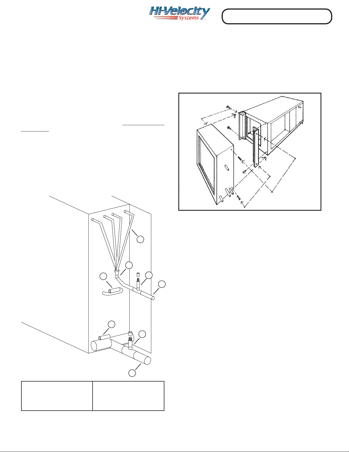
When refrigerant lines are connected to the RCM-I coil, high
and low side access ports must be connected as well. (Fig. 01 -
reference 2 & 6) With the use of a tee and reducer this process is
simplied. The access ports are required for system startup and
for future trouble shooting or service. When reading refrigerant
pressures/temperatures, always read them at the evaporator
access ports.
RCM-I modules can be used on any R-410A condenser if
R-410A refrigerant components are used. All Energy Saving
Products R-Series modules come standard with R-410A
refrigerant components.
This module is for use with HVS-36 and HVS-60 Inverter
Heat Pump Condensing Units. It does not come with thermal
expansion valve, as there are internal EXVs inside the Heat
Pump. When installing the RCM-I Modules, DO NOT INSTALL
WITH TXVs.
The module will come with access ports that will need to
be installed to read refrigerant pressures/temperatures at the
Evaporator (RCM-I). Fig. 01 shows approximate installation
locations for these components.
RCM-I Modules were designed to be used with the HVS-
36 and HVS-60 Heat Pumps but can be used on any R-410A
Condensing Unit, as long as a TXV is installed as well. All Energy
Saving Products cooling modules come standard with R-410A
refrigerant components.
1) Liquid line
2) High side access port
3) Refrigerant distributor
4) Distributor tubes
5) Suction line
6) Low side access port
7) Suction line temperature port
8) Middle coil temperature port
1
2
3
4
5
6
7
7
Mounting Brackets
Mounting the cooling coil to the fan coil can be done with
the L brackets supplied (Fig. 02), ensure that no screws puncture
the drain pan or coil. Page 8 has the dimensions of the cooling
modules.
Note: 7 & 8 coil temperature ports are explained in Module HVS - Heat Pump Manual
Fig. 01 - Coil Assembly
www.hi-velocity.com
Fig. 03 - P-Trap, Secondary Drain Pan
Module RCM-I
RCM-I Installation
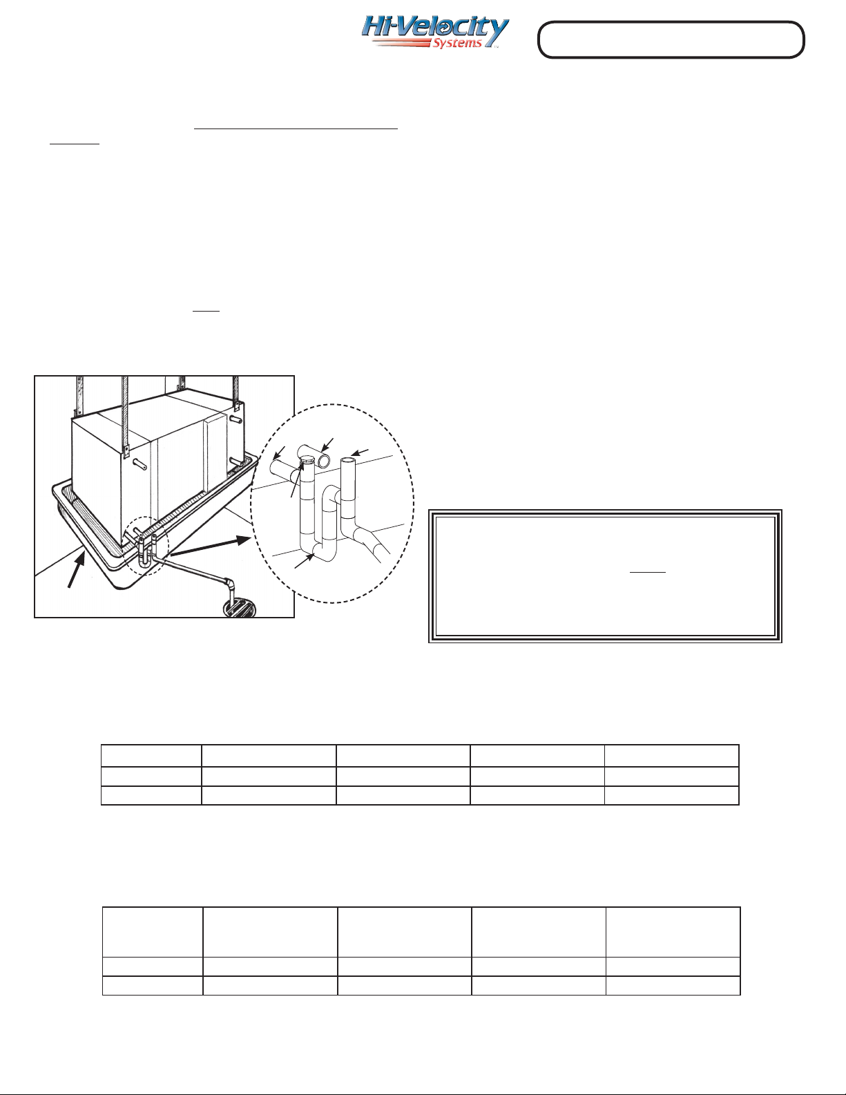
P - Trap
The condensate drain must have a minimum 3” P-Trap
installed (Fig. 03), and run at a slope of ¼” per foot in the
direction of the drain. All RCM-I modules come with a ¾” male
CPVC primary outlet and a ¾” secondary outlet. When installing
the P-Trap it must be installed on the primary outlet. It is good
practice to install a tee and a cap right above the P-Trap to act as
a clean out, in the event of the drain line being plugged. If a vent
is to be installed, it must be on the drain side of the P-Trap, and
must comply with all local building code requirements. If code
requires a secondary drain line, run the secondary line using the
same method. Otherwise, having it drain into a secondary drain
pan is acceptable. If the coil is located above a nished area,
a secondary drain pan must be installed. An equipment
stand/riser or rubber equipment mat may be necessary to
elevate the module o of the ground to allow for the P-Trap.
Piping the RCM-I
Only refrigerant grade pipe and ttings are to be used with
the RCM-I Module. Plumbing ttings may contain wax or other
contaminants which are detrimental to the proper operation of
the system. Insulate the suction line with a minumum of 3/8”
insulation. For inverter heat pump applications, insulating both
suction and liquid lines is mandatory. In high heat areas, a
minimum of 1/2” insulation may be needed. Support the pipe
every 5 feet, or whatever local code states.
Run the pipes in the most direct route possible, taking into
account structural integrity, building details and local building
codes. Minimum refrigerant pipe length is 16ft (6m). If going less
than 16 ft, coil the additional copper pipe up in horizontal loops
to ensure proper oil return. If the evaporator is located above
the condenser, slope any horizontal runs toward the condenser.
If the condenser is located above the evaporator, a P-trap must
be installed at the bottom of the vertical riser. For long vertical
risers, additional P-traps must be installed for every twenty feet.
Lines running over 213’ (65m) are not recommended.
Pipe Sizing
Refer to charts below and Module HVS - Variable Speed Heat
Pump Manual for pipe sizing.
The HVS Variable Speed Heat Pump comes with a factory charge. Additional charge will only be needed on line sets
longer than 49 ft. (See Table 02 below)
Model Liquid Line Suction Line Maximum Length Maximum Lift
HVS-36 3/8” (9.5 mm) 5/8” (15.9 mm) 213.25’ (65 m) 98.4’ (30 m)
HVS-60 3/8” (9.5 mm) 3/4” (19 mm) 213.25’ (65 m) 98.4’ (30 m)
Table 01 - Minimum pipe sizes, maximum length and maximum lift
Model Liquid Line Suction Line Factory Charge (kg)
Add extra refrigerant
for line sets
over 49 ft (15 m)
HVS-36 3/8” (9.5 mm) 5/8” (15.9 mm) 6.75 lbs (3.06 kg) 1 oz/ 3.3 ft
HVS-60 3/8” (9.5 mm) 3/4” (19 mm) 10.15 lbs (4.6 kg) 1 oz/ 3.3 ft
Table 02 - Minimum pipe sizes (up to 98’), factory charge and additional refrigerant required
Pipe Sizing
Vent
P-Trap
Secondary
Drain
Primary
Drain
Clean
Out
Secondary Drain Pan
Important: Return Air must be ltered
before entering the cooling module.
Module RCM-I - RCM-I Coil Installation (3/8)
www.hi-velocity.com
Module RCM-I
RCM-I Installation
Outdoor Unit Installation
Locate the outdoor unit in a suitable location, as close as
possible to the fan coil. Maintain the clearances recommended
in the HVS Variable Speed Heat Pump manual to ensure proper
airow. The outdoor unit must be installed level, in a properly
supported location. If proper refrigerant piping techniques are
used, a liquid line bi-directional lter/drier is not needed. More
information can be found in module HVS - Variable Speed Heat
Pump Manual.
Evacuating
The system must be brazed under a nitrogen purge to
prevent oxidation of the pipe during the brazing process. After
the piping is installed and all components have been brazed
together, a vacuum pump must be used to properly evacuate
the system from both of the access ports to 1500 microns, to
ensure system is free of contaminants. Add refrigerant to the
system to bring the pressure above zero psig. After allowing
the refrigerant to absorb moisture, repeat the above procedure.
Evacuate the system to 500 microns on the second evacuation,
and ensure that the system holds at the vacuum pressure. If not,
check for leaks and evacuate again. If the vacuum holds, add
refrigerant to raise the pressure to 2 psig. At this point open
service valves on pre-charged condensing units.
The use of an electronic leak detector is recommended, as it is
more sensitive to small leaks under the low pressures.
Once the system has been determined clean and ready for
charging, refrigerant can be added. The service valves on the
condenser must be open at this time. By referring to page 5 in
the HVS Heat Pump Manual, if additional refrigerant is needed,
weigh in the recommended amount. Truly, the only way to tell
if the system is properly charged is by pulling out all refrigerant,
then weighing it back in based on the factory charge listed on
the rating plate, plus any additional refrigerant needed based
on page 5 of Module HVS - Variable Speed Heat Pump Manual.
Charging
Wiring – Outdoor Unit
Make all connections to the outdoor unit with rain tight
conduit and ttings. Most building codes require a rain tight
disconnect switch at the outdoor unit as well (always check
local codes). Run the proper size copper wires to the unit, and
connect as per the manufacturer’s recommendations.
The RCM-I coil can operate at a level that is dierent from most
other conventional system coils. This coil is supplied refrigerant
by a variable speed condenser/compressor, so refrigerant
pressures and temperature can vary as well. Temperature
and pressure reading aren’t as important for a refrigeration
technician to know in a variable speed heat pump condensing
unit.
Important: Failure to follow the proper
evacuating and charging procedures may
void warranty.
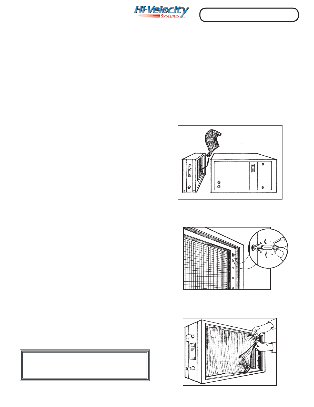
Carry-over Screen
All RCM-I refrigerant cooling modules come supplied with
a nylon mesh carry-over screen and six stand-o plugs. The
Hi-Velocity units have a very high humidity removal rate, it is
possible for the airow across the coil to grab moisture o the
ns and carry it into the unit. With the carry-over screen in place
it reduces the chance of moisture being carried into the unit.
Ensure that the nylon mesh is placed on the exiting air side of
the cooling module (Fig. 4)
Installation Instructions
The Carry Over Screen is placed on fan coil side of the cooling
module (Fig. 04).
Fig. 04 - Screen on the fan coil side
On the fan coil side of the cooling module, attach three plastic
stand-os down each side of the cooling coil (Fig. 05).
Fig. 05 - Attach stand-off plugs
Place the nylon wire mesh over the stand-os, ensuring the
screen touches the drain pan. Then snap the screen over the
plastic stand-os (Fig. 06).
Fig. 06 - Attach screen to coil
Module RCM-I - RCM-I Coil Installation (4/8)
www.hi-velocity.com
Return Air
When sizing the return air ducts, keep in mind that if they are
too small they can create noise, but if they are too large, the fan
coil cannot build up proper pressure. Table 03 has recommended
return air sizes for round and rectangular ducts. A variance of
plus 20% is allowable for sizing return ducts that connect to the
Hi-Velocity Systems unit.
It is recommended to install a grill that is 10 - 20% larger than
specications require, this will ensure that there is no air velocity
noise at the grill. Where allowed by local codes, a single return
air grill may be used. When using exible duct for return air, use
one duct size larger due to the higher friction loss.
The Return Air is to be sized on a 0.15 static pressure (37
pa) as compared to 0.10 static pressure (25 pa) for conventional
forced air systems. The maximum length for an individual return
air duct is fty feet (15.24m).
Duct Sizing
Please note: It is VERY important NOT to
undersize the return air, as this will create
noise, increase motor power consumption,
reduce airow and increase the possibility of
condensate carry-over.
Table 03 has recommended return air sizes for round and
rectangular ducts. A variance of +20% is allowable for sizing
return ducts that connect to the RCM-I or Hi-Velocity Systems
unit.
Where allowed by local codes, a single return air grill may be
used. Note: Return air grill must have equal minimum of free air
area to return air.
Table 03 – Return Air Duct Sizes
Unit Rigid Ø Flex Ø
Min Sq.
Inches
(Sq. cm)
50/51/52 12”
(305mm)
14”
(356mm)
120
(774cm)
70/71 12”
(305mm)
14”
(356mm)
120
(774cm)
100/101 14”
(356mm)
16”
(406mm)
168
(1084cm)
Remember: When using exible duct for return air, use
one duct size larger due to the higher friction loss.
Important: When connecting a round
Return Air duct to the RCM-I coil, a round to
rectangular transition is required.
Important: When using exible duct for
return air, use one duct size larger due to the
higher friction loss.
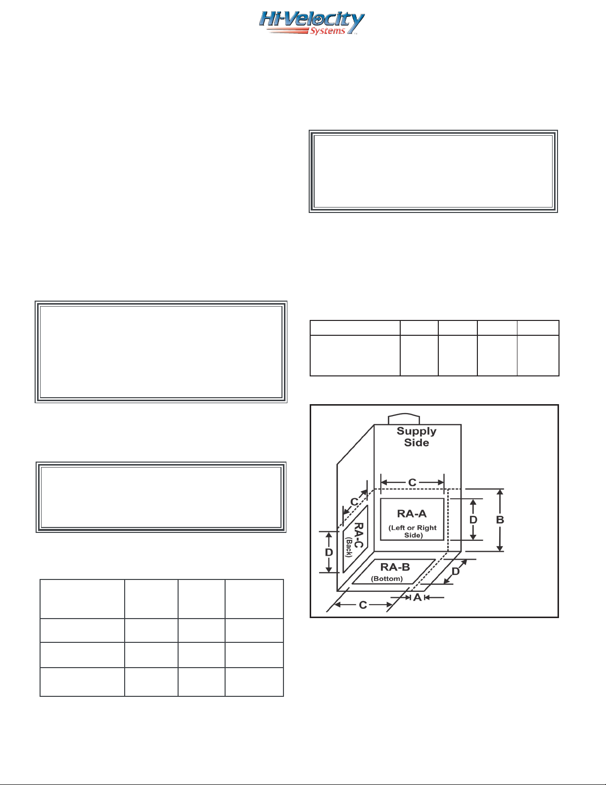
Return Cutout
Fig. 07 shows the dierent locations the return air can
be installed on Hi-Velocity fan coils. Table 03 contains the
dimensions needed for the return. All fan coils are equipped with
return air knockout cuts and can be used as a proper return air
size.
Model A B C D
50/51 H/BU
70/71 H/BU
100/101 H/BU
3”
3”
3”
17”
17”
17”
10”
15”
22”
14”
15”
15”
Fig. 07 - Return air cutout sizing
Legend
RA - Return air
Notes:
• DO NOT cut past the center plate or electrical
box (Dim A & B).
• 100 and 140 Units CANNOT use return air “C” (RA-C).
• This drawing is NOT to scale.
Table 03 - Return Air Cutouts
Module RCM-I - RCM-I Coil Installation (5/8)
This manual suits for next models
2
Table of contents
Popular Heat Pump Accessories manuals by other brands

AIT
AIT Hydraulic Station operating manual

Resol
Resol SBS 2000 Manual for the specialised craftsman

STIEBEL ELTRON
STIEBEL ELTRON SBB 301 WP Installation and operating instructions

Jandy
Jandy R0412001 installation instructions

Flow
Flow HyPlex Prime Major Installation

Solflex
Solflex SonaSafe HC Series manual


Immergas
Immergas MAGIS HERCULES PRO MINI 6 Instruction and warning book

DOMUSA TEKNIK
DOMUSA TEKNIK FUSION COMBI W 50 Installation and operating instructions

STIEBEL ELTRON
STIEBEL ELTRON MAE Operation and installation

Nibe
Nibe EF 45 Installer manual

Pentair Jung Pumpen
Pentair Jung Pumpen PKS-D 1000 Series Mounting instructions

STIEBEL ELTRON
STIEBEL ELTRON SB-VTI 100 Operation and installation