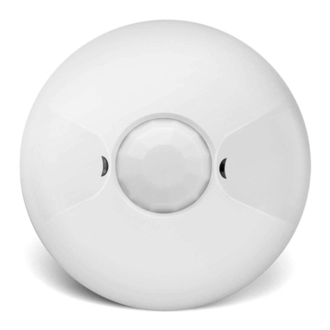
Enerlites MPC-50H Quick start guide

MPC-50H-L1: Mounting height: 50ft Field of view: 360° Coverage :2800 sq.ft
Adjustable Light Level..................................................10FC—150FC
@ 120VAC, .............................................................0-800W ballast or tungsten
DESCRIPTION
MPC-50H
SPECIFICATIONS
Voltage ...........................................................120/277VAC, 50/60Hz
Load Requirements:
@ 277VAC, ..............................................................................0-1200W ballast
@ 120VAC ...............................................................................................1/4 hp
Sensitivity Adjustable.................................50% or 100%(DIP switch)
Coverage:
Operating Temperature ................................32°to 131°F (0°to 55°C)
Relative Humidity .......................................20-90%, non-condensing
Material........................................................................................ABS
-LED indicator of occupancy detection for easy verification of coverage
-Easy front access to time delay, sensitivity range and ambient light
-Hardware choices for side and back mount
-Compatible with all program start ballasts
-Zero crossing circuitry reduces stress on relay and extends sensor life
The MPC-50H occupancy sensor is designed for automatic lighting
control in high bay applications,such as warehouses,distribution cen-
-ters, gymnasiums, and areas with direct access to the lighting fixtures,
sensor (PIR) .
MPC-50H-L2: Mounting height: 8ft Field of view: 360° Coverage :1200 sq.ft
FEATURES
DESCRIPTION
WARNING: Turn the power off at the circuit breaker before
The MPC-50H-L1 coverage pattern
Lens choice:
The coverage area is determined by the type of lens attached to the
MPC-50H. (See Figure 1).
The MPC-50H-L2 coverage pattern
Figure 1
installing the sensor
1.Determine the mounting location appropriate to the sensor and the
coverage area. Careful consideration must be given to sensor where
the edge of the fixture, shelving or other obstructions may block the
sensor’s line of sight . Mount the sensor below the edge of the fixture
and away from the fluorescent lamps so that the heat from the lamps
does not affect the sensor.
2.Make sure that you have the appropriate accessories for the sensor
COVERAGE
INSTALLATION
MPC-50H-L1
Sensor including
backbox and lens
MPC-50H-L2
Sensor including
backbox and lens
0.65"
0.69"
2.60"
0.65"0.70"
2.61"
Turn the potentiometer on the sensor to the "-”, if adequate ambient
light,the output of sensor will be inhibited, and the load can not be on;
only when the ambient light is down to a certain level the sensor will auto-
1 .Avoid mounting the sensor close to heat source.
2 .Adjust during daylight hours when ambient light in
the area reach the desired level. Open the Front
Cover and adjust the Light level.
mounting configuration. (See Mounting Options.)
3.Connect the line voltage and load wires to the sensor leads as shown
in the Wiring Diagram
Do not allow bare wire to show.
Make sure all connections are secure.
4.Attach the MPC-50H as shown in the assembly drawing on the next
page.
5.Restore power from the circuit breaker.
Refer to the wire diagram of the sensor (See Figure 2)
1.Connect the hot wire to the black wire from the sensor
2.Connect the neutral wire to the white wire from the sensor
3.Connect the load wire to the red wire from the sensor
Figure 2
-matically turn on.Therefore,potentiometers require customers to adjust
in accordance with the location and the ambient light level.
Turn the potentiometer on the sensor
ambient light level.The load will be as long
occupancy.
WIRING
LIGHT LEVEL ADJUSTMENT
INSTALLATION INSTRUCTIONS
-01- -02- -03-
-Easy mounting using 1/2'' knockout at end of luminaire fixture
specifically for indoor locations.This product contains a passive infrared
level adjustment
High Bay 360° Passive Infrared Line Voltage
Occupancy Sensor
Neutral
Hot Load
MPC-50H
Black
Red
White
Figure 2
LOW VIEW
HIGH VIEW
20ft 10ft 0ft 10ft 20ft
15
22ft 13ft 7ft 3ft 0 3ft 7ft 13ft 22ft .
8 ft
Typical
desk-top
level
44 ft
13.4 m
50 ft
30ft 20ft 10ft 0 10ft 20ft 30ft
to the "+”, regardless of the
as there are signals from

SENSOR ADJUSTMENT
INSTALLATION INSTRUCTIONS
TROUBLESHOOTING
MOUNTING OPTIONS
4. The chase nipple provided can be pushed into a standard 1/2”
The MPC-50H can be attached to the fixture or junction box using the
back box and chase nipple or directly to the fixture surface via the two
screw holes provided in the sensor (See Figure 3 below).
Figure 3
Back box mounting
This requires a standard 1/2” knockout for the chase nipple.The Sensor
mounts to the back box with a bayonet type fitting requiring a slight
twist of the units to separate them or lock them into place.The box
comes ready for side mounting(See Figure 4). It can be modified
for rear mounting as follows:
1. Pop out the cap in the rear 1/2'' knockout.
2. Un-snap the chase nipples from the side mount and snap into the
rear mounting hole.
3. Use the cap to close the side mount hole.
knockout in a metal fixture [max of 1 mm (0.04”) thick metal]
without the need for the included internal nut. The nut can be
used for added security if necessary.
Note: There is a 60-second warm-up period when power is
first applied, LED flashes
If the sensor detects occupancy during the warm-up, the time delay
will increase.
If no occupancy is detected during the warm-up,the light turns OFF
after the initial 60-second warm-up period.
The sensors are factory preset to allow for quick installation in most
applications.After test is finished,adjust the potentiometer according
PIR Sensor
Surface
Mounting
Screw Hole
DIP Switches
Detection
Indicator LED
CDS
Light Level
Adjustment Trimpot
Surface
Mounting
Screw Hole Check sensor mounting place, verify the sensor can detect motion
Warning:Turn off the power at the circuit breaker before
WARRANTY INFORMATION
installing.
LED does not blink:
from human body. If not , the LED will not blinks.
LED blinks but lights do not turn ON:
1.Make sure the wire connections are correct. Red load wire lead to
load light, and check the connection security.
2.Make sure that power to the sensor has been ON continuously for
at least one minute. Wait for the warm-up period to end,and if LED
flashes,the load has not turn on,then go to next step.
3.Cover the light sensor lens to simulate darkness.If the light turns
ON,the light level setting needs to be adjusted.If set for minimum,
more than 2fc of ambient light causes the lights to be held OFF.
4.Check security of the light fixture.
Lights will not turn OFF:
1.If there is no motion from people or equipment in the sensor’s view
but the LED blinks, look for any nearby source of infrared energy
(heat) in motion,such as turbulent air from a heating or cooling
Mount the sensor so that it’s lens is below the edge of the fixture
and does not directly view the lamps.
Move the air supply away from the sensor,or move the sensor.
2.Verify time delay set in switches 2-4.The time delay can be set
from 15 seconds to 30 minutes. Ensure that the time delay is
set to the desired delay and that there is no movement within
the sensor’s view for that time period.
3.Check sensor wire connections,verify load and neutral wires
are secure.
Sensitivity setting: DIP switch 1
1. 50%,sensor’s coverage is smaller, just about half of the widest range.
2. 100%,the maximum range of MPC-50H-L1 coverage is 2800 square
feet,while for MPC-50H-L2 coverage is 1200 square feet.
Time delay: DIP switch 2,3,4
The sensor will hold on the lights on as long as occupancy is detected.
The time delay countdown starts when no motion is detected.After no
motion is detected for the length of the time delay, the sensor will turn
the lights off.
The MPC-50H has 4 DIP switches under the cover.They are used to
set sensitivity and time delay feature settings.
Time Delay 2
Test/15 Seconds
5 Minutes
10 Minutes
15 Minutes
20 Minutes
25 Minutes
30 Minutes
34
Sensitivity
100%
50%
1
DIP SWITCH SETTING
=OFF =ON Factory setting
-04- -05- -06-
to the ambient request specification,such as sensitivity and time delay.
Back Box
Alignment
Guides
OR
MPC-50H
Lens
Figure 4
supply.
Our company warranties this product to be free of defects in materials
and workmanship for a period of two (2) years.There are no obligations
or liabilities on the part of our company for consequential damages arising
out of, or in connection with, the use or performance of this product or
other indirect damages with respect to loss of property, revenue or
profit, or cost of removal, installation or reinstallation.
Nov, 2014
22003A
Table of contents
Other Enerlites Accessories manuals
Enerlites
Enerlites PL20R User manual
Enerlites
Enerlites DWOS-J User manual
Enerlites
Enerlites MPC-50V User manual
Enerlites
Enerlites MPW-L User manual
Enerlites
Enerlites MPC-50L User manual
Enerlites
Enerlites DWHOS User manual
Enerlites
Enerlites MPC-50H User manual
Enerlites
Enerlites MWOS User manual
Enerlites
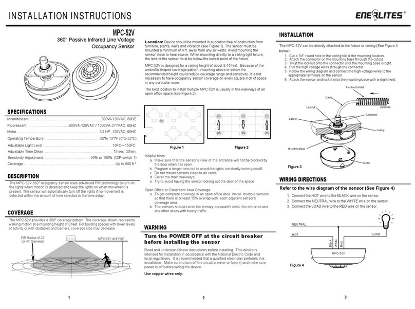
Enerlites MPC-52V User manual
Enerlites
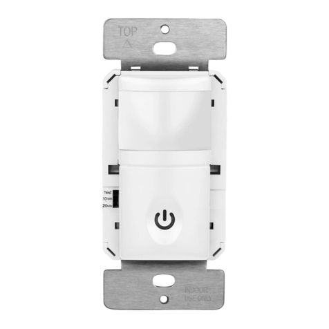
Enerlites HMVS User manual


