Enerpac YPA3174D User manual

1
YPA3174D
Instruction Manual

Hydraulic Technology Worldwide
AIR DRIVEN HYDRAULIC PUMPS
YPA3174D 1500bar
INSTRUCTION MANUAL
3
Figure 1
Parts list:
3 AIR PRESSURE FILTER REGULATOR UNIT
6 GLYCERINE FILLED GAUGE D160 mm SCALE 0-2000 bar
8 MAXIMATOR PUMP UNIT M-189D
11 OUTPUT OIL PORT
14 SAFETY VALVE
15 SHUT OFF VALVE
21 OIL RESERVOIR CAPACITY 10 L
25 INPUT AIR PORT 1/2 BSP
34 AIR GAUGE
42 AIR BALL VALVE

Hydraulic Technology Worldwide
AIR DRIVEN HYDRAULIC PUMPS
YPA3174D 1500bar
INSTRUCTION MANUAL
4
Figure 2

Hydraulic Technology Worldwide
AIR DRIVEN HYDRAULIC PUMPS
YPA3174D 1500bar
INSTRUCTION MANUAL
5
1.0 SAFETY FIRST !!!
Read all instructions, warnings and cautions
carefully. Follow all safety precautions to avoid
personal injury or property damage during
system operation. Enerpac cannot be
responsible for damage or injury resulting from
unsafe product use, lack of maintenance or
incorrect product and/or system operation.
Contact Enerpac when in doubt as to the safety
precautions and operations.
IMPORTANT: Before using the product
it’s important for the operator to read the
instructions and to understand the precautions,
the warnings, and to apply the local codes of
security.
2.0
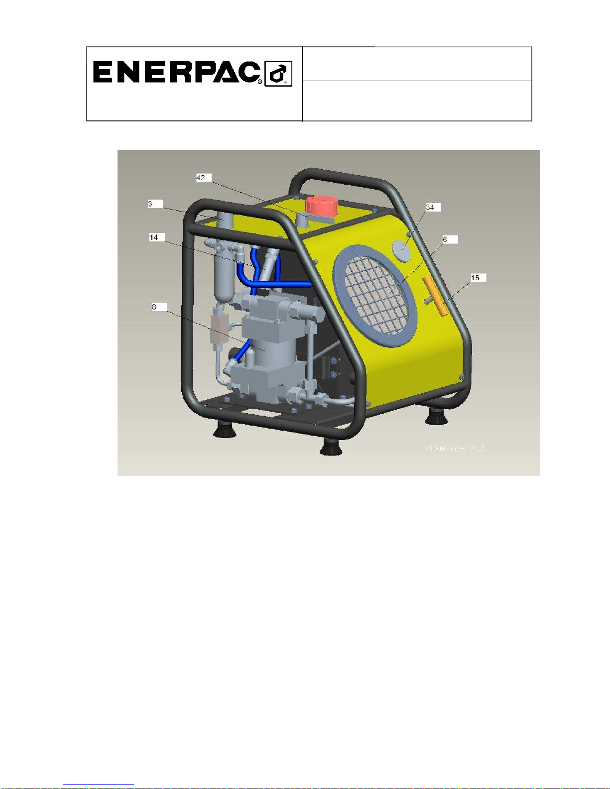
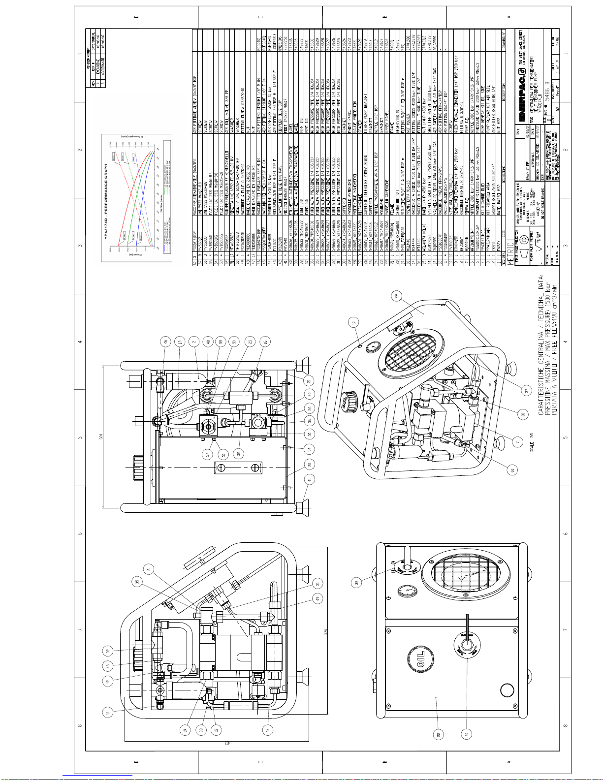
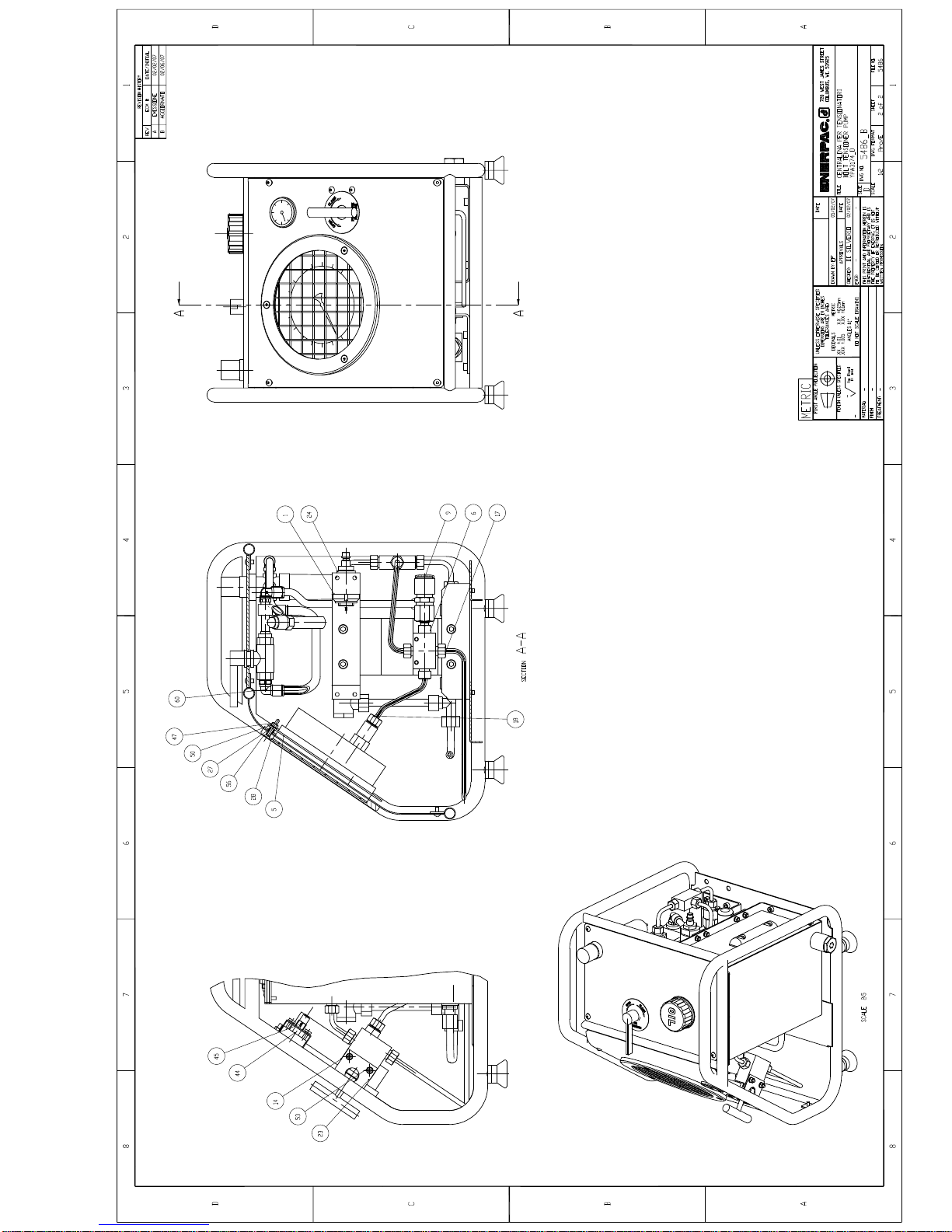
DESCRIPTION OF THE PRODUCT :
The “ENERPAC” air driven hydraulic pumps
model YPA3174D , are manual pumps realised for
single acting tensioners, the components are
described in fig. 1 and 2, while the characteristics of
the pump M189D are indicated in the graph page 7.
In fig.2 we find the air input for alimentation of the
pump (pos.25), made of a fitting with ½ BSP thread
to be equipped with an air fitting, not include,
compatible with the equipment where the pump will
be used. The oil output(pos. 11) is a female rapid
coupler
.
3.0 INSTALLATION
3.1 GENERAL: The Enerpac pumps are supplied
ready to use, complete with hydraulic oil. The
safety valve is preset as the relief valves.
These values can be changed only by qualified
personal.
3.2 PRELIMINARY OPERATIONS:
1
Position the pump near the work area, assure
that the hoses and the pendant can reach easily
the wrench.
2Check that the alimentation of the
compressed air is able to give a
minimum of 300 Nl/min at 6.5 bar
3
Check the pressure setting as described at point
3.3
4 Check that the couplers are well connected..
ATTENTION: Always mount the protection
caps on the couplers when not used. Do not
pressurise flexible hoses without connecting the
couplers.
3.3 REGULATION PRESSURE:
Verify what is the working pressure needed for
the tensioning
Connect the alimentation hose to the fitting for
air alimentation pos. 25
Connect the flexible oil hose at the output of the
pump (pos. 11) leaving the other hose end with
the coupler free(the hose must be able to be
pressurized)
ATTENTION: avoid that the hose free end,
during the pressure regulation is pointing towards
persons or animals; an eventual break of the coupler
could eject metal parts which could be harmful.
Lift and turn counterclockwise the air tap on the air
regulator(pos.3) until it is completely open
Shut the the relief valve(pos. 15) turning clockwise.
Open the air valve(pos. 42).
Turn clockwise the air tap (pos.3) slowly until you
reach the working pressure of the oil(see the
performance graph pag.7) shown on the gauge of
the front panel(pos. 6), while trough the air valve it
is possible to the air pressure
When the working pressure is reached close the air
valve(pos. 42)
Lock the air tap, lowering it(pos.3) and open the
relief valve(pos. 15) turning counterclockwise to set
the pressure of the circuit to zero

Hydraulic Technology Worldwide
AIR DRIVEN HYDRAULIC PUMPS
YPA3174D 1500bar
INSTRUCTION MANUAL
6
ATTENTION:
Please consult the
tensioner manual.for the correct use.
Note:
do not change the settings of the safety valve
4.0
OPERATIONS :
4-1
TENSIONING :
Verify that the hose has no air in it, if not, go
to procedure 6
Verify that the coupler is clean
Attach the hose at the oil output of the
pump(pos.11) and to the tensioner which we
suppose correctly positioned and ready for the
tensioning.
Verify that the coupler is correctly attached
Start the tensioning operation:
•
Close the relief valve (pos.15)
•
Open the air valve(pos. 42)
•
Wait until the final pressure is
reached, looking at the gauge(pos.6)
•
Tighten the bolts with the correct
tensioning procedure.
4.2 LOOSENING:
•Close the air valve(pos.42)
•Open the relief valve(pos.15)
Before disconnecting the hose
5-0
STORAGE
Disconnect hoses both from the pump and from the
tensioner
Clean the pump with a soft rag.
Protect the couplers with the dust caps.
Roll up the hose and put them away in a place not
near to heat sources.
Check that the tensioner does not leak oil, place it
in a dry place and not near to heat sources
Respecting this procedure is essential to operate
in security and prevents malfunctions.
6-0 PROCEDURE FOR AIR BLEEDING
HOSES
•
Find a compatible coupler like the on
on the hose
•
Mount the coupler on one end of the
hose
•
Mount the hose on the output port of
the pump(pos.11)
•
Close the relief valve(pos.15)
•
Open the air valve(pos.42)
•
Wait to see the oil leaking from the
free end of the hose
•
Close the air valve and dismount the
hose

YPA3174D - PERFORMANCE GRAPH
0
500
1000
1500
2000
2500
0,00
0,04
0,08
0,12
0,16
0,20
0,24
0,28
0,32
0,36
0,40
0,44
Oil Flow (l/min)
Pressure (bar)
0
100
200
300
400
500
600
700
Air Consumption (lN/min)
Air Pressure at 4 bar Air Pressure at 6 bar
Air Pressure at 8 bar Air Consumption at 4 bar
Air Consumption at 6 bar Air Consumption at 8 bar
8 bar
6 bar
8 bar
4 bar
6 bar
4 bar


Table of contents
Other Enerpac Power Pump manuals
Popular Power Pump manuals by other brands

Patterson
Patterson RC Operation and maintenance manual

Greenlee
Greenlee 940-PS Operation, service and parts instruction manual

ITT
ITT ICB Installation, operation and maintenance instructions

Kodiak
Kodiak PWP2HX owner's manual

Pittsburgh Automotive
Pittsburgh Automotive 3 CFM two stage owner's manual

BLACKMER
BLACKMER ProVane PV6B Installation, operation and maintenance instructions