Service Information Sheet
POWERFUL SOLUTIONS. GLOBAL FORCE.
ZU4 Classic Bolting Pump
Single-Solenoid Control Valve Upgrade
INTRODUCTION
This document applies to all Enerpac ZU4 Classic Bolting Pumps
equipped with dual-solenoid valves. It includes instructions for
performing the following product upgrade procedures:
• Replacement of the existing VE Series dual-solenoid control
valve with the new single-solenoid VE Series control valve.
• Replacement of the existing front and middle brackets with
new brackets that are electrically compatible with the single-
solenoid control valve.
ELECTRICAL SERVICE KITS AND VALVES
To upgrade an existing pump to use the new single-solenoid
control valve, a new electrical service kit must rst be installed.
Refer to Table 1 for service kit model numbers and descriptions.
TABLE 1 - ELECTRICAL SERVICE KITS
Pump Voltage Service Kit
Model Number
Description
115V ZTERK-115 ZTW 115V Electrical
Service Kit
230V
NORTH AMERICA
ZTERK-230 ZTW 230V Electrical
Service Kit
230V CE
EUROPE AND ASIA (Contact Enerpac)
Each electrical service kit includes a new front electrical bracket,
middle electrical bracket and pendant. The pump's existing rear
electrical bracket is reused.
New single-solenoid control valves are available in various
voltages and congurations as described in Table 2.
TABLE 2 - CONTROL VALVE MODELS, SINGLE-SOLENOID
Pump
Voltage
Valve Model Description
115V VE42Q-115 115V 10,000 PSI [700 bar]
VE42QM-115 115V 10,000 PSI [700 bar]
- Multiport
VE42E-115 115V 11,600 PSI [800 bar]
VE42EM-115 115V 11,600 PSI [800 bar]
- Multiport
230V VE42Q-230 230V 10,000 PSI [700 bar]
VE42QM-230 230V 10,000 PSI [700 bar]
- Multiport
VE42E-230 230V 11,600 PSI [800 bar]
VE42EM-230 230V 11,600 PSI [800 bar]
- Multiport
Note: Control valves and electrical service kits must be ordered
separately.
230 VOLT CE MODELS IMPORTANT NOTE
Consult your local Authorized Enerpac Service Center before
beginning electrical upgrade procedures on 230V pumps with
CE style electrical components. Power cord wire colors and
various other wiring details are dierent for 230V CE models.
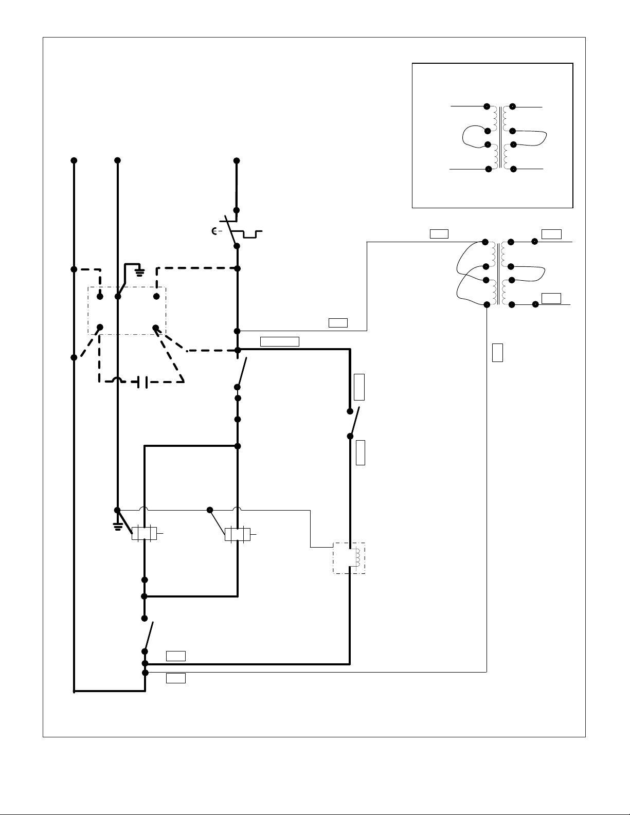
A complete wiring diagram covering all pump wiring
congurations and voltages - including 230V CE models - is
shown in Figure 14 of this document.
BEFORE YOU BEGIN
WARNING:
Disconnect power from pump before
beginning the following procedure. Be sure hydraulic
pressure is zero (0) psi/bar.
CAUTION:
Standard safety procedures are to be
followed during disassembly and reassembly to
minimize any possibility of injury.
CAUTION:
Allow only trained and qualied personnel
to perform the electrical wiring procedures described in
this document.
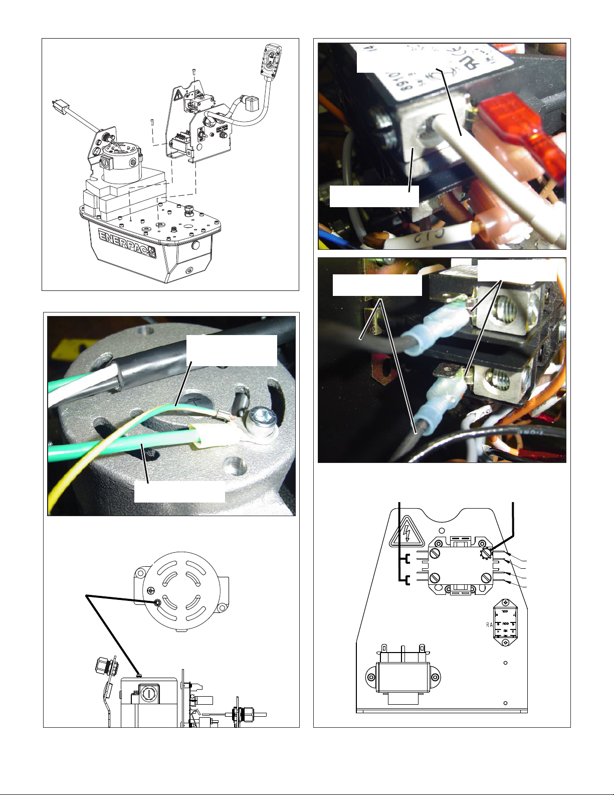
IMPORTANT: Some components on the new front and middle
brackets are pre-wired at the factory, prior to shipment Be
careful not to disturb wiring when unpacking the shipment or
during installation procedures.
Note: The graphics contained in this document are provided for
reference and instructional purposes only. Various pump features
and/or congurations may be dierent than shown for your pump.
Optional features may be shown that are not present on your pump.
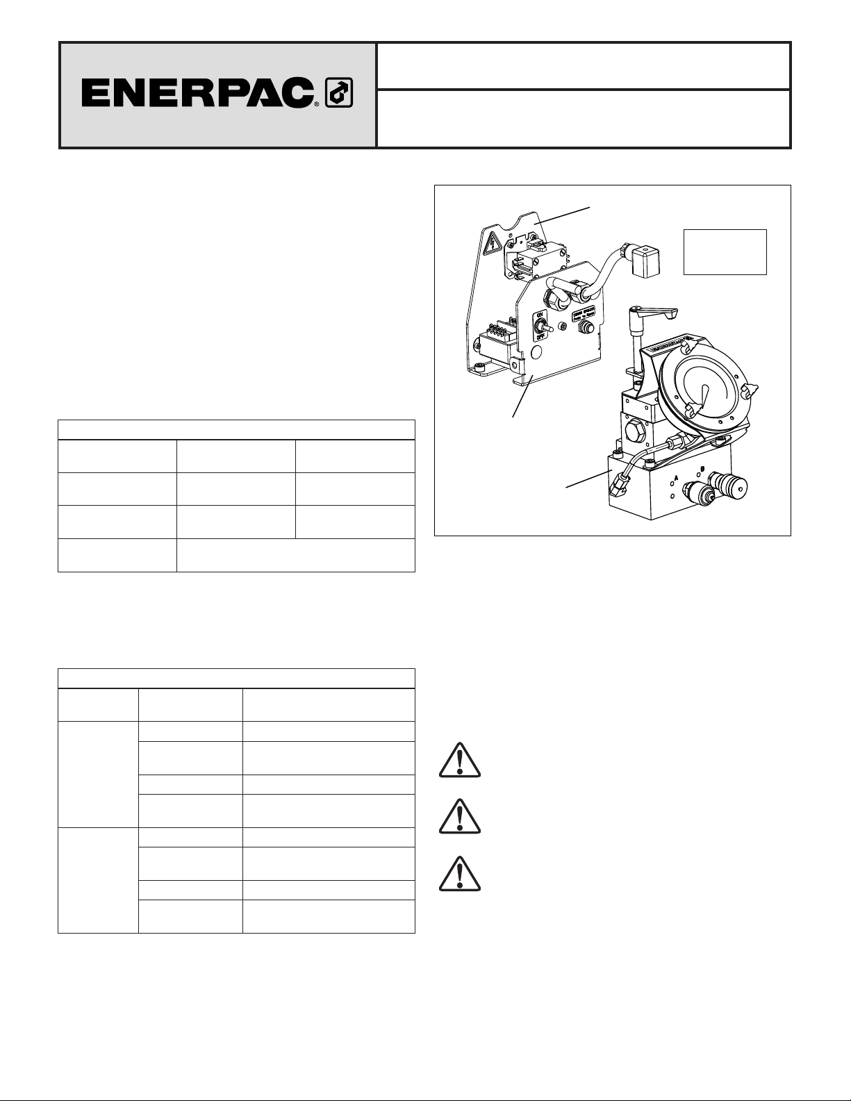
Figure 1, New Components (typical)
L2915 Rev. B 08/22
*
Middle Bracket*
VE Series Control
Valve Assembly
(single-solenoid)
Included with
Electrical
Service Kit
*
Front Bracket
and Pendant
(not shown)