EnerSys Wi-iQ 4 User manual
Wi-iQ®
BATTERY MONITORING DEVICE
www.enersys.com
4
Owner’s Manual


WI-IQ®4 BATTERY MONITORING DEVICE
OWNER’S MANUAL
3
TABLE OF CONTENTS
1. Features................................................................................3
2. Technical Specifications......................................................3
3. Dimensions ..........................................................................5
4. Installation............................................................................5
5. Communication ...................................................................6
6. Service and Troubleshooting..............................................9
1. FEATURES
The Wi-iQ®4 battery monitoring device is the fourth generation of battery sensor
technology, providing incremental features such as Bluetooth and CAN-Bus connectivity
to improve communication and integration with other devices and external equipment.
Features added to the new compact design include three LEDs to communicate status,
a new LCD display to show important battery information and an audible alarm.
• Programmable
• Wi-iQ4 device can be assembled on batteries from 24V to 80V
• Small and slim fit
• IP65 enclosure
• Available for flooded lead acid and NexSys®TPPL battery chemistries
• Single or dual cable current sensors
• LCD display and low voltage alarm buzzer
• Memory capable of more than 8,000 events
• Multiple communication channels
• Zigbee®wireless to Wi-iQ Report PC software and charger
• Bluetooth to E Connect™ mobile app and Truck IQ™ smart battery dashboard
• Newly designed E Connect mobile app enables fast and easy check-up of battery
fleet and data sharing
• Connection with our external Truck iQ device that shows real time data to operator
about battery status, alarms and remaining working time
• Optional CAN-Bus module provides State of Charge (SOC) and other data to any
CAN network (e.g. lift trucks, AGVs)
• Compatible with Xinx™ warehouse management efficiency system to simplify both
data collection and reporting
• Wireless communication with EneSys®modular charger allows for better asset
control
• Adjustable SOC Warning and provides an audible alarm
• Eliminates need for separate Low Voltage Alarm (LVA) device
NOTE: The Wi-iQ4 device is designed to install only on a battery and will not
function properly if mounted on the truck side of battery connector for a power
study.
2. TECHNICAL SPECIFICATIONS
Item Description
Nominal Battery Voltage 24VDC to 80VDC
Operating Voltage 15V-120V
Operating Temperature 4ºF (-20ºC) – 140ºF (60ºC)
Bi-directional Current
Measurement
Allows for throughput data collection using a
Hall effect sensor which can measure up to +/-
1000A.
1A resolution
Voltage Measurement Continuous monitoring of overall battery voltage
and half battery voltage
Voltage Accuracy 0.1V
Temperature External thermistor
Altitude <2,000m (<6,561ft)
Electrolyte Level Detection With electrolyte sensor
Wireless Interface Zigbee (SMAC -2.4Ghz), Bluetooth BLE
Real Time Clock Time keeping and stamping of data
Data Storage Upload data to PC via Dongle, to Cloud server via
E Connect mobile app
Data Collection Up to 8,000 event log records
Wireless Range Up to 10m (32ft) (Zigbee); up to 5m (16ft) (BLE)
CAN Communication 2 different CAN protocols: CANOpen or J1939
Power Consumption 1 Watt
Protection Over voltage
Reverse Polarity Protection
Packaging
Water and acid resistant
UL 94V-0
Pollution level 3 protection (dusty environment)
IP65 enclosure
Physical Dimensions 40,07mm L x 19,5 mm W x 107,97mm H
Compliance
Electrical Equipment (Safety) Regulations
2016 (S.I. 2016/1101)
Directive 2014/35/EU :
Safety
BS EN 61010-1 : 2010 / A1 : 2019
EMC Regulations 2016 (S.I.2016/1091)
Directive 2014/30/EU :
Electromagnetic compatibility
BS EN 12895 : 2015 / A1 : 2019
Directive 2011/65/EU
RoHS
Radio Equipment Regulations 2017
(S.I.2017/1206)
Directive 2014/53/EU
ETSI EN 301 489-1 V2.2.3 (2019)
ETSI EN 301 489-17 V3.2.2 (2019)
ETSI EN 300 328 V2.2.2 (2019)
THIS DEVICE COMPLIES WITH PART 15 OF THE FCC RULES. OPERATION IS
SUBJECT TO THE FOLLOWING TWO CONDITIONS:
(1) THIS DEVICE MAY NOT CAUSE HARMFUL INTERFERENCE
(2) THIS DEVICE MUST ACCEPT ANY INTERFERENCE RECEIVED, INCLUDING
INTERFERENCE THAT MAY CAUSE UNDESIRED OPERATION.
IN ACCORDANCE WITH FCC REQUIREMENTS, CHANGES OR MODIFICATIONS NOT
EXPRESSLY APPROVED BY ENERSYS COULD VOID THE USER’S AUTHORITY TO
OPERATE THIS PRODUCT.
Technical support: Reference www.enersys.com to find your local contact.
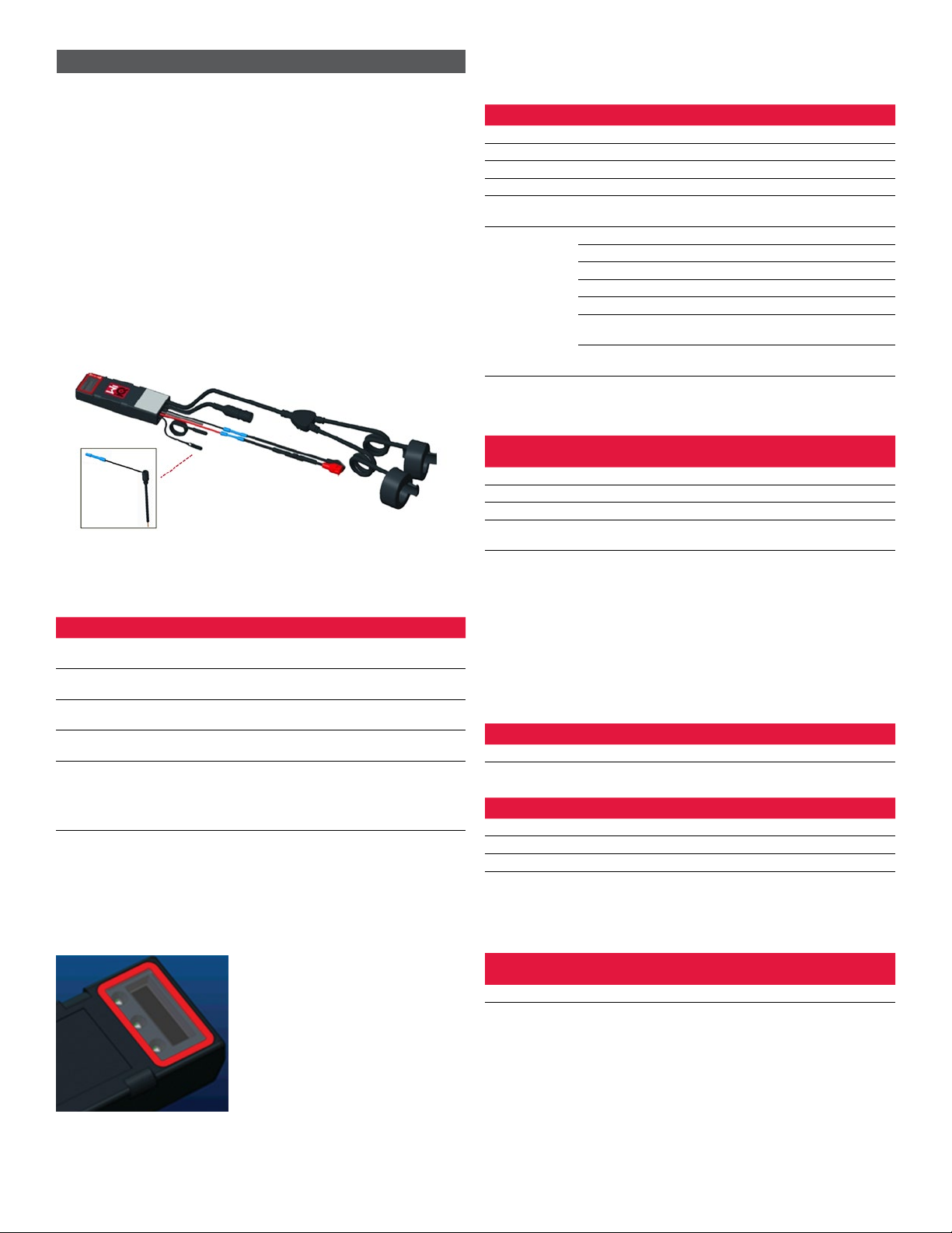
2.1 Components
Figure 1: Wi-iQ4 Device for Flooded Batteries with Electrolyte Probe
4
4
2. TECHNICAL SPECIFICATIONS (CONTINUED)
2.2 The Wi-iQ®4 Battery Monitoring Device
2.2.1 The Wi-iQ®4 battery monitoring device consists of:
• A main unit (for voltage measurement, display, LEDs, buzzer and
communication features)
• 1 or 2 current sensors
• A CAN connection (Use is optional)
• Red/Black cables to power the Wi-iQ4 device
• Balance/Gray wire for mid battery voltage
• Temperature probe
• Electrolyte level probe for flooded battery version
• 3 crimping splices + 3 cable ties
• Installation hardware
Figure 2: Wi-iQ4 Device for Thin Plate Pure Lead (TPPL) or Valve Regulated Lead
Acid (VRLA) with CAN Connector; without Electrolyte Probe
2.3 The Wi-iQ4 Device Part Numbers
2.3.1 There are four part numbers available.
Table 1: Part Numbers
Part Number Reference P/N Description Battery Type
WIIQ4 6LA20743-E0E Wi-iQ4 monitor Basic flooded
single sensor Flooded
WIIQ4DUAL 6LA20743-E3E Wi-iQ4 monitor Basic
VRLA single sensor Gel, TPPL
WIIQ4F 6LA20743-E1E Wi-iQ4 monitor Premium
CAN single sensor All with CAN
WIIQ4DUALF 6LA20743-E2E Wi-iQ4 monitor Premium
CAN dual sensor All with CAN
6LA20761 6LA20761
Electrolyte sensor (replacement
part only) do not use this
number when ordering
part number WIIQ4 and
WIIQ4DUAL
Flooded
2.4 The Wi-iQ4 Device Display and LEDs
2.4.1 An LCD display and three LEDs on the Wi-iQ4 device provides status
indication. The display is turned OFF after 15 minutes of no activity
(sleep mode). A small touch to the Wi-iQ4 display will turn the display
back ON.
Figure 3: Display and LEDs
2.4.2 Parameters displayed.
Table 2: Parameters
Description Value Comment
SOC 0-100% State of Charge of the battery
Battery Voltage Ex: 27.2V Overall battery voltage (V)
Temperature Ex: 64°F (18°C) Battery Temperature
Current Ex: 10.4A Current value in A (+ charge, - discharge)
Bluetooth
Connected
When the smartphone is connected
to the Wi-iQ4 device
Warning
Level Blue LED ON
Temperature Red LED Flashing or ON
Low SOC Warning Buzzer ON
Low SOC Alert
Unbalance Blue LED flashing
No Current Sensor CURRENT/SENSOR
NO/SIGNAL
No Temperature
Sensor
TEMP/SENSOR
NO/SIGNAL
2.4.3 LED Colors and Functions
Table 3: Colors and Functions
LED Color Lit Fast blinking
(0.5s ON / 0.5s OFF)
Left Red High Temperature Warning Temperature
Center Orange Alert DOD Warning DOD
Right Blue Low level Unbalance
All Fast blink every 5 seconds
(for normal operation)
NOTE: When the Wi-iQ4 device is first connected to the battery voltage, all
LEDs are flashing and Firmware revision is shown on the display (initialization
sequence). The SOC shown will be a reloaded value from the manufacturer. To
start, please set the device and reset the value (refer to the configuration section
of the manual).
2.5 Buzzer
2.5.1 There is a buzzer located inside the main unit. The buzzer is activated
when the SOC of the battery is low and the battery needs to be
charged. Reference Table 5.
Table 4: Warning and Alert Time Frequency
Normal SOC Warning SOC Alert SOC
Buzzer OFF 2 chirps every 20 seconds 1 chirp every 5 seconds
Table 5: Default value of the buzzer vs. battery type
Battery Type* Warning SOC Alert SOC
NexSys TPPL NXS models 30% 20%
NexSys TPPL NXP models 50% 40%
Others 30% 20%
*Adjustable
2.6 The Wi-iQ4 Device Current Sensor(s)
2.6.1 The current sensor is a solid core hall effect device.
Table 6: Current Sensor Technical Specification
DC Cable Gauge* AWG Internal
Diameter
Truck Class
Recommendation Max DC Current
Up to 120mm2Up to 4/0 20.1 mm Class 1, 2 & 3 1000A
NOTE: The DC cable gauge does not consider the terminal lug or contact
dimensions. Terminal lugs or contacts may need to be assembled after inserting
the cable in the current sensor. Mostly for the 4/0 cables.
5
2. TECHNICAL SPECIFICATIONS (CONTINUED)
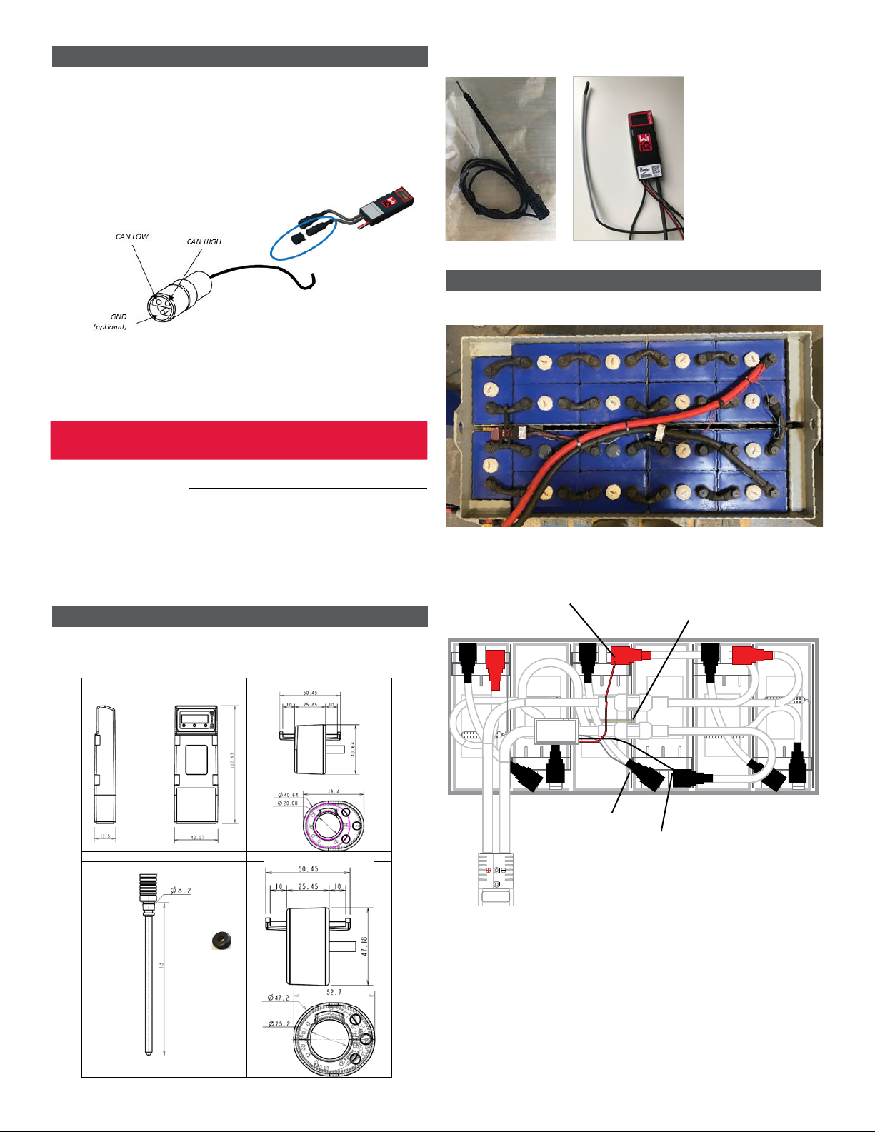
2.7 Wi-iQ®4 Device CAN option
2.7.1 If equipped, the Wi-iQ®4 device communicates via CAN protocol.
2.7.2 The Wi-iQ4 device main unit is delivered with a protective plastic cap
that needs to be removed to use the CAN option.
2.7.2.1 The female connector pinout is described below.
Figure 4: Female Connector
2.7.2.2 Male connector is NOT included (ITT-CANON SURE-SEAL IP68
3-contact receptacle with two pins and one socket adapted for
0.75-1.5mm2wires).
Table 7: CAN Connector Specification
Product Receptacle
Part Number
Contact Part Number
Wire Gauge Pin (qty 2) Socket (qty 1)
ITT-CANON
SURE-SEAL
120-8551-001
(SS3R)
0.5–1.0mm2330-8672-001
(SS20)
031-8703-001
(SS20)
0.75–1.5mm2330-8672-000
(SS10)
031-8703-000
(SS10)
2.7.3 The Wi-iQ4 device CAN communication adopts two different CAN
protocols:
2.7.3.1 CANOpen
2.7.3.2 J1939
2.7.4 Refer to section 5.7 for proper documentation.
3. DIMENSIONS
3.1 Wi-iQ4 Device and Hall effects overall dimensions (mm)
Figure 5: Dimensions
Figure 6: Probes and Sensors
4. INSTALLATION
Figure 7: Wi-iQ4 Device Final Assembly on 2V Cell Tray
Figure 8: Wi-iQ4 Device Final Assembly on 12V Block Tray4.
(CONTINUED4. IN
NOTE: The stack order on the stud is: Battery Cable, Wi-iQ4 Device Ring Terminal,
Flat Washer, Lock Washer and Nut.
4.1.1.1 Ensure the threads on the nut and stud are clean,
place a drop of blue Loctite™ on the stud and
tighten the nut in place.
4.1.1.2 Torque the nut to the proper specification (above).
Ensure the battery cable lug is flat against the
plate.
Red wire
Temperature sensor
Gray wire
Black wire
Wi-iQ4
Temperature SensorElectrolyte Probe
1. Dimensions
Wi-iQ4
Current sensor USA
Level sensor 6LA20761
Current sensor EMEA/APAC
NB: All dimensions are given in mm.

6
5. COMMUNICATION
There are two modes of communication (Wireless and CAN) available on the Wi-iQ®4
device:
5.1 Wireless
5.1.1 BLE
5.1.1.1 Connect to a smartphone via E Connect mobile app
5.1.1.2 Connect to Truck iQ™ smart battery dashboard
5.1.2 Zigbee®(legacy protocol in use with previous generations of Wi-iQ
device)
5.1.2.1 Connect to chargers (NexSys®+ battery charger)
5.1.2.2 Connect to Wi-iQ Report software
5.1.2.3 Connect to Xinx™ software
5.2 The Wi-iQ4 device can be configured and provide data via Zigbee®(Wi-iQ
Report – v5.4.5 minimum) or BLE (E Connect app – v2.16 minimum).
5.3 CAN (Controller Area Network)
5.3.1 CANOpen Cia 418 or J1939
5.3.1.1 Interface with truck using an Original Equipment
Manufacturer (OEM) proprietary CAN protocol implemented.
5.3.1.2 Interface with AGV using EnerSys proprietary CAN protocol.
5.4 Configuring Wi-iQ4 Device within Wi-iQ Reporting Suite
5.4.1 Once the device is installed, it must be set-up in the software. Plug
a dongle (Wi-iQ antenna) into the USB port of a PC with the Wi-iQ
Reporting Suite installed. Start Wi-iQ Report software.
5.4.2 Click on the Software menu item in the upper left corner; click
“Language” and select “US” (not English). This is necessary to ensure
all the battery technologies (Bat. Techno) are available later in the
software setup.
5.4.3 Create a new site if one does not already exist. The naming of the site
is not important for installation purposes.
Figure 9: Wi-iQ Report Website Configuration Page
5.4.4 Double-click on the Site Name to open it. Previously added devices may
be shown. To add a new device, click on the scan button at the top left.
The software will scan for all available devices. Check the “Add” box
for all devices you wish to configure and hit the “+ Add” button on the
right. The devices can be identified by matching the Address (HEX) field
to the S/N on the device.
Figure 10: HEX Address Match5. COMMUNICATION (CONTINUED)
5.4.5 The devices you have added should now be added to the site view.
If you have added multiple devices at once and you are unsure which
device is on each battery, click on the eye icon in the left column. This
will make all the LEDs on that device blink for 15 seconds. The device
will also beep during the same period. Double click anywhere along
the line of the device the device you wish to configure to open the
configuration window.
5.4.6 **If at any time the Laptop version will not pick up the Wi-iQ®4
device or find correct serial number of device, configure correctly
through Econnect app on appropriate serial number, scan again
and it will now show up in your Wi-iQ Suite on your laptop.
Figure 11: Wi-iQ4 Report Website Homepage
7
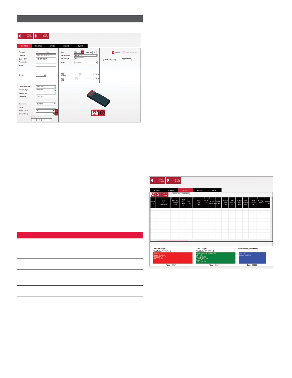
Figure 12: Wi-iQ®4 Report Website Device Configuration Page
5.4.8 Battery SN# – Enter the battery serial number (9 digits).
5.4.9 Fleet number – As required
5.4.10 Model – Enter the battery type, ex: 18-E100-21
5.4.11 Cells – Enter the number of cells on the battery
5.4.11.1 For NexSys®TPPL 2V batteries, use total voltage divided by
2 to determine number of cells. Example – The battery type is
36NXS700. 36 describes the total voltage of the battery. Take
this number and divide by 2 to get “Cells”; in this example,
36 / 2 = 18 cells.
5.4.12 Cells Bal. – Enter the cell number where the gray wire was installed,
counting from the positive post.
5.4.12.1 For NexSys TPPL Bloc Battery: The black Wi-iQ4 device
wire and the gray Wi-iQ4 device wire should be attached to
the negative and positive posts of the same bloc as described
in section 4.1.13. In this configuration “Cells Bal.” will always
be 6.
5.4.13 Battery Technology – Select the appropriate type of battery.
Refer to line-item notes on BaaN order requesting any
specific Battery Technology setting by customer or sales
representative. If nothing is requested in the line item notes,
refer to Table 8.
Table 8: Charge Profiles
Battery Technology Battery Types
COLD STORAGE All Flooded with average battery temperature below
59°F (15°C)
FAST US 85P(FC), 125P(FC), E100X, E140X
HG FLOODED* E55L, E75L, E110, E155
LOW MAIN* Deserthog (E90D, E100D, E125D)
NexSys 2V NexSys TPPL 2V (NXS)
NexSys BLOC NexSys TPPL Bloc (NXS)
NexSys TPPL 2V Not used in North America
NexSys TPPL Bloc NexSys TPPL Bloc (NXP)
OP CHARGE All Flooded
STD FLOODED All Flooded
*NOTE: The charge profile will be STD FLOODED when HG FLOODED, or LOW
MAIN are selected. The purpose of selecting HG FLOODED, or LOW MAIN is to
inform the Data Analyst of the specific type of battery being reviewed.
5.4.14 Capacity (Ah) – Enter the nominal Ah of the battery.
5.4.14.1 NexSys TPPL Bloc Battery: Determine total battery Ah.
Example: 24-12NXS186-3. 186 describes the amp hour rating
of each block and 3 describes the number of parallel strings.
Multiply these two numbers to get “Capacity (Ah)”; in this
example 186 X 3 = 558 Ahrs.
5.4.14.2 NexSys TPPL 2V Battery: Determine total battery Ah.
Example: 18-NXS770. The 770 describes amp hour rating.
5.4.15 (+) cable/(-) cable – Select the cable the Wi-iQ4 device has been
installed on. In most cases, (-) cable should be selected.
5.4.16 Equal. Period (hours) – Enter 186. This is the time in hours to request
equalization charge (only available with Wi-iQ4 device firmware v4.0
and higher). If equal time is set to 0 hours, this disables the feature
and critical faults are not recorded on reports. This feature is not
programmable for NexSys battery profiles.
5.4.17 Balance – Check this box for all batteries.
5.4.18 Water Level Probe – Check this box for all batteries with an electrolyte
probe installed.
5.4.19 Mode – Leave as default – CYCLES, unless line-item notes on Order
Acknowledgement requires an alternative mode setting by customer
or sales representative. Note: Click on the “WRITE IDCARD” button
prior to changing the mode. If mode is changed first, then restart
configuration from step 5.6.1.
5.4.19.1 Xinx™ Systems require the Mode to be EVENT.
5.4.20 Dates – Enter the date from the battery date code for the “Date
Manufac. Bat.” Field. Enter the date the battery is placed in service for
the “Date Inst. serv.” field. Leave all other date fields blank.
5.4.21 Owner – Leave as default – ENERSYS.
5.4.22 Battery Group – Enter truck type – Sit Down, Reach, etc., or as
designated by customer.
5.4.22.1 For Xinx, refer to the Xinx set-up worksheet.
5.4.23 Charger Group – Charger Model or Charger Max Output
5.4.24 Summertime Setting: OFF/Europe/Australia.
5.4.25 Once you have entered all of the required information, click on the
“WRITE IDCARD” button. Select the “Write” button and confirm
settings are written.
5.4.26 Click on the “CYCLES” tab. Find the button called “Reset Cycles” and
click on it, select “Continue” when the warning message appears. This
will erase any memory in the device. Installation is now complete. It is
important to reset the data on a new installation for proper averaging
calculations.
5.4.26.1 “Reset Events” for Xinx or any setup requiring EVENT Mode.5.
COMMUNICATION (CONTINUED)
Figure 13: Reset Cycle Button
5.4.27 Xinx™ System Setup
5.4.27.1 Change mode to EVENT
5.4.27.2 The Battery Group must be set for the correct Pool Name in
accordance with the note on the order and/or the Xinx BOM
profile; e.g. Dock Stockers, Pallet Jack, etc. If you use all
capital letters for one pool, make sure all the pools are named
using all caps. This will be provided via a custom note on the
order and/or the Xinx BOM profile. Any typo may result in the
Xinx system failing to recognize the battery.
5.4.28 Use the “MEASURES” tab to verify setup
5.4.28.1 Select the “MEASURES” button to read Wi-iQ®4 device
real-time data
5.4.28.1.1 Measure voltage from the positive terminal of the
battery to the VBAL/CEL gray wire with a calibrated
voltmeter. Divide the reading by the number of
cells between the positive terminal and the balance
wire. Compare this value to the “VBAL/CEL”
reading and confirm is within a tolerance of (+/- .02
VDC). Deviation from this value indicates the wrong
number of cells was input into the “Cells Bal” field,
or the Balance Wire is in the wrong location.
5. COMMUNICATION (CONTINUED)

5.4.38.1.2 Measure the voltage between the positive and
negative battery post with a calibrated voltmeter.
Divide the number of cells in the battery and
confirm this value is within a tolerance of (+/- .03
VDC) of the value in “VBAT/CEL”. Deviation from
this value may indicate a bad electrical connection.
Clean and grease the battery post and terminal lug.
5.4.28.1.3 Measure the temperature near the Temperature
Probe on the battery. Verify the value in the
“Temp” field is near the as read value. Large
deviations indicate a bad thermal sensor.
5.4.28.1.4 If possible, operate the equipment or charge the
battery. Measure the current with a calibrated
clamp-on ammeter and confirm the value is within
(+/- 2%) tolerance of the value in “CURRENT”.
Deviation from this value indicates a bad Hall Effect
Sensor.
5.4.28.1.4.1 Also verify the current is in the proper
direction, (-) for discharger and (+) for
charge. Deviation from this indicates
the Hall Effect Sensor was installed
backwards.
5.4.28.1.5 Verify the electrolyte indicates properly. If the
probe is covered and the indication in “Measures”
is not green, verify the balance wire is on the
negative post of the same cell the electrolyte probe
is installed.
Figure 14: Live Readings on Wi-iQ4 Report
5.5 Configuring Wi-iQ®4 device within the E Connect™ mobile app
5.5.1 A mobile app called “E Connect” is developed for iOS®and Android®
operating systems (will not work on Windows platforms), available for
download for free from App Store and Play Store. Access is protected
by login/password. Different access levels will be granted through
different access codes.
5.5.2 The E Connect mobile app allows mainly:
5.5.2.1 Scanning and then associate the Wi-iQ4 device to a customer
site (list of devices will be automatically recorded on a remote
server).
5.5.2.2 Setting the Wi-iQ4 device battery parameters (such as
technology, capacity…).
5.5.2.3 Quick review of historical parameters such as SOC, voltage
and temperature.
5.5.2.4 Downloading the Wi-iQ4 device history data (data downloaded
are automatically transferred to a remote server* - there is no
data stored on the Smartphone).
Notes:
(1) When launching the mobile app, Bluetooth is automatically activated.
(2) If the Smartphone is not connected to Internet during scan and data download,
the transfer to the remote server will be done as soon as the Internet connection
is restored.
5.5.3 The main screens of the E Connect mobile app with the main
parameters are shown below.
Figure 15: E Connect Mobile App Screens
5.5.4 Refer to 5.4 “Configuring Wi-iQ®4 Device within Wi-iQ Reporting Suite”
to configure the battery parameters in the Wi-iQ4 device settings page
of the app. The info required is the same (ie battery s/n, customer info,
battery technology, battery capacity, number of cells, etc).
Figure 16: E Connect™ Mobile App Available Menu Options
5. COMMUNICATION (CONTINUED)
8
9
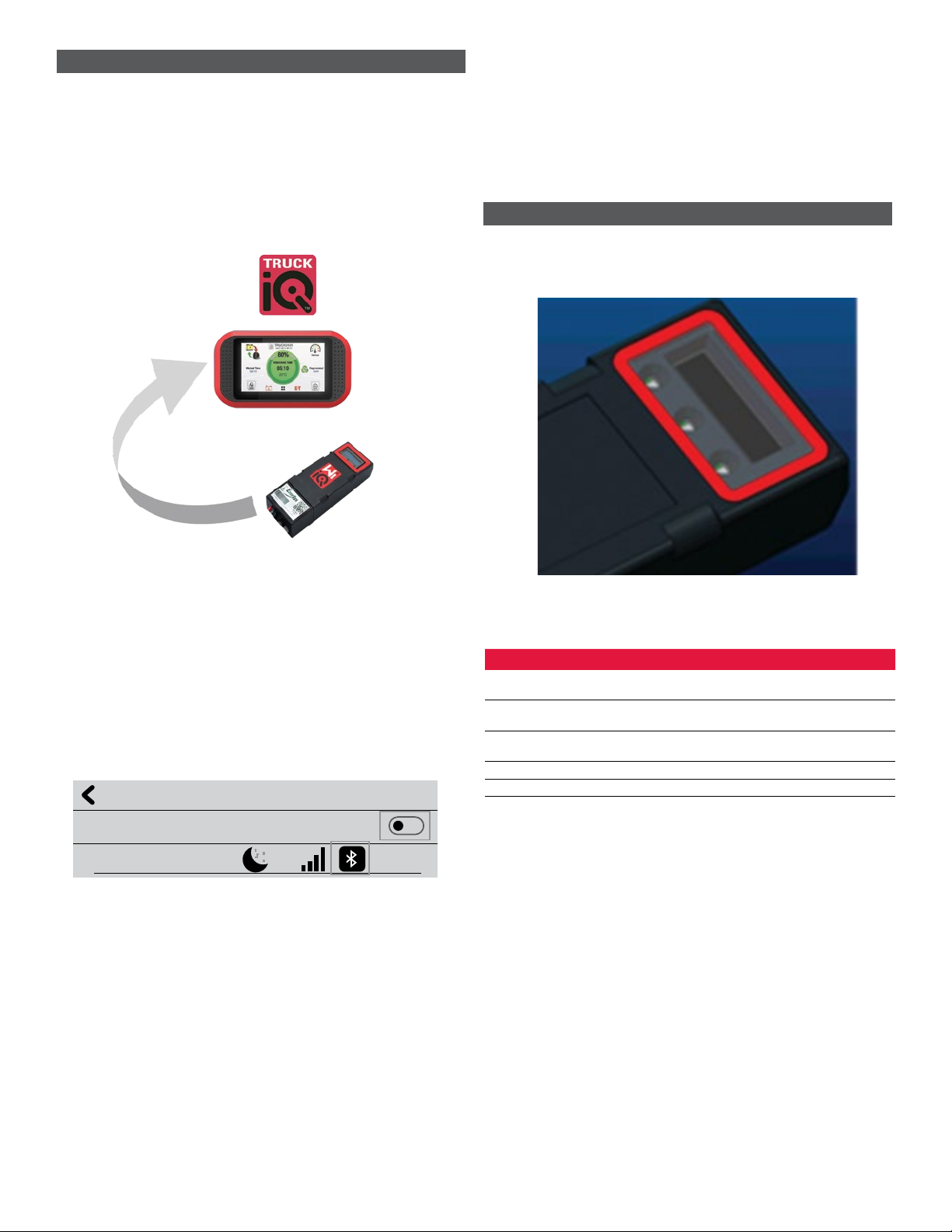
5.6 Truck iQ™ smart battery dashboard
5.6.1 The Truck iQ™ smart battery dashboard is one of the latest “iQ”
devices from EnerSys®.
5.6.2 The device consists of a display powered by the battery via the truck
cables. It reads in real time and wirelessly data from the Wi-iQ®4
device, displaying alerts, alarms, SOC and other useful parameters to
optimize the operation of the battery.
Figure 17: Wi-iQ4 Device Communicates with Truck iQ Smart Battery Dashboard to
Display Critical Battery Information
5.6.3 Pairing Truck iQ dashboard with Wi-iQ4 device
5.6.4 The Truck iQ dashboard can be paired with the Wi-iQ4 device either
manually or automatically.
5.6.4.1 Manual Procedure
Figure 18: Wi-iQ4 Device and Truck iQ Dashboard Pairing Instructions
5.7 CAN (Controlled Area Network) Communication
5.7.1 EnerSys®allows integration via CAN supported protocols interfacing
with the following:
5.7.1.1 Trucks using OEM’s proprietary CAN protocol implemented in
the Wi-iQ4 device firmware.
5.7.1.2 AGVs (Automated Guided Vehicle) using EnerSys proprietary
CAN protocol (CANOpen Cia 418 or J1939).
5.7.1.3 List of parameters communicated via CAN to trucks as
specified by OEMs proprietary protocol, but not limited to:
5.7.1.3.1 USOC (Usable State of Charge)
5.7.1.3.2 DC Bus Voltage
5.7.1.3.3 DC Bus Current
5.7.1.3.4 System temperature ( battery temperature)
5.7.1.3.5 Lift Lock-out trigger
5.7.1.3.6 Limited Operation trigger
5.7.1.4 For more details, please refer to CAN Interface Specification
provided with the truck’s user manual for each specific OEM.
5.7.1.5 Parameter communicated via CAN to AGV as specified by
EnerSys proprietary CAN protocol, but not limited to:
5.7.1.5.1 USOC (Usable State of Charge)
5.7.1.5.2 DC Bus Voltage
5.7.1.5.3 DC Bus Current
5.7.1.5.4 System temperature (battery temperature)
5.7.1.6 For more details, please refer to EnerSys Global: CAN Open
and CAN J1939 specification for battery controller document
ENER-CO-002’ and document EnerSys_J1939.
6. SERVICE AND TROUBLESHOOTING
6.1 Displayed error messages
Figure 19: Wi-iQ4 Device LEDs6. SERVICE AND TROUBLESHOOTING )
6.1.1 Check the LED indicators on the device. Fast blinking every five
seconds of all LEDs indicates successful setup and normal operation.
Refer to the table below for troubleshooting other indicators:
Table 9: Diagnostic Table
LED Indicator LCD Display Meaning
Fast blink every
5 seconds Installation OK
Flashing Blue Balance installed or programmed
incorrectly
No temp sensor Level probe not inserted or incorrectly
programmed
No current sensor Hall effect not connected or not reading
Flashing Red Temperature Possible bad thermal probe (if persistent)
6.1.2 Connect to the device with the E Connect™ mobile app
6.1.2.1 If it won’t connect, verify no other devices are connected, such
as another App or Truck iQ™ dashboard. It can only connect to
one device at a time.
6.1.2.2 Try to connect with a computer and Wi-iQ®Report
6.1.2.3 If it doesn’t connect to either device. Move the Wi-iQ4 device
to another area, preferably outdoors.
6.1.2.3.1 If it connects in another location, the problem is
radio magnetic interference.
6.1.2.3.2 If it does not connect, replace the Wi-iQ4 device
6. S6.1.3 Perform the following quality checks to confirm proper installation.
Compare values displayed on the LCD with variables measured from the
battery (i.e., voltage, temperature, etc.).
6.1.3.1 Select the “MEASURES” button to read Wi-iQ4 device real-
time data
6.1.3.1.1 Measure voltage from the positive terminal of the
battery to the VBAL/CEL gray wire with a calibrated
voltmeter. Divide the reading by the number of
cells between the positive terminal and the balance
wire. Compare this value to the “VBAL/CEL”
reading and confirm is within a tolerance of (+/- .02
VDC). Deviation from this value indicates the wrong
number of cells was input into the “Cells Bal” field,
or the Balance Wire is in the wrong location.
Pairing
Setting -> I/O -> Pairing -> Disable Auto pairing.
Select the appropriate Wi-iQ4 device by clicking on the BLE
(Bluetooth) icon.
NB: The Wi-iQ4 device is normally equal to the battery name.
Auto Pairing
24V30T3AH
5. COMMUNICATION (CONTINUED)

10
6.1.3.1.2 Measure the voltage between the positive and
negative battery post with a calibrated voltmeter.
Divide the number of cells in the battery and
confirm this value is within a tolerance of (+/- .03
VDC) of the value in “VBAT/CEL”. Deviation from
this value may indicate a bad electrical connection.
Clean and grease the battery post and terminal lug.
6.1.3.1.3 Measure the temperature near the Temperature
Probe on the battery. Verify the value in the
“Temp” field is near the as read value. Large
deviations indicate a bad thermal sensor.
6.1.3.1.4 If possible, operate the equipment or charge the
battery. Measure the current with a calibrated
clamp-on ammeter and confirm the value is within
(+/- 2%) tolerance of the value in “CURRENT”.
Deviation from this value indicates a bad Hall Effect
Sensor.
6.1.3.1.4.1 Also verify the current is in the proper
direction, (-) for discharger and (+) for
charge. Deviation from this indicates
the Hall Effect Sensor was installed
backwards.
6.1.3.1.5 Verify the electrolyte indicates properly. If the
probe is covered and the indication in “Measures”
is not green, verify the balance wire is on the
negative post of the same cell the electrolyte probe
is installed.
6.1.3.1.5.1 If installed correctly, inspect the
probe for corrosion. Replace probe if
damaged.
6.2 For service, contact your EnerSys sales represeentative or visit
www.enersys.com.
6. SERVICE AND TROUBLESHOOTING (CONTINUED)


EnerSys World Headquarters
2366 Bernville Road
Reading, PA 19605, USA
Tel: +1-610-208-1991 /
+1-800-538-3627
EnerSys EMEA
EH Europe GmbH
Baarerstrasse 18
6300 Zug, Switzerland
EnerSys Asia
152 Beach Road
#11-08 Gateway East Building
Singapore 189721
Tel: +65 6416 4800
© 2023 EnerSys. All rights reserved. Trademarks and logos are the property of EnerSys and its aliates except Bluetooth, Loctite, Noalox,
CE, UKCA, Zigbee, iOS and Android, which are not the property of EnerSys. Subject to revisions without prior notice. E.&O.E.
EMEA-EN-OM-ENS-WIQ-1023
Table of contents
Other EnerSys Measuring Instrument manuals


