EnerSys Wi-iQ3 User manual

User Manual of Wi-iQ3 ENGLISH
Protective cover
Current sensor
1. Main unit
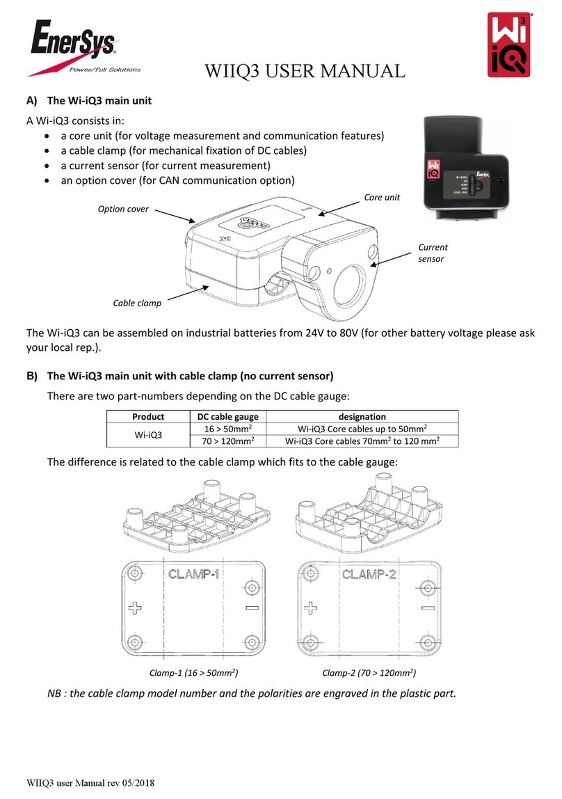
The Wi-iQ3 consists of:
• a core unit (for the measurement and communication
features).Therearetwomodels,oneforindustrialbatteries
from24Vto80Vandoneforindustrialbatteriesfrom96Vto
120V.
• acableclamp(formechanicalxationofDCcables)
• acurrentsensor(forcurrentmeasurement)
• anoptioncover(forCANcommunicationoption)
TheWi-iQ3canbeassembledonindustrialbatteriesfrom24V
to80V.TheWi-iQ3120Vcanbeassembledonbatteriesfrom
96Vto120V.
2. Main unit with cable clamp (no current sensor)
There are four core part-numbers depending on the DC cable
gauge:
Product DC cable gauge Designation
Wi-iQ3
16>50mm2Wi-iQ3 core cables up to
50mm2
70>120mm2Wi-iQ3 core cables 70mm2
to120mm2
Wi-iQ3120V
16>50mm2Wi-iQ3 core cables up to
50mm2
70>120mm2Wi-iQ3 core cables 70mm2
to120mm2
Thedifferenceisrelatedtothecableclampwhichtstothe
cablegauge:
Clamp-1 (16 > 50mm2)
Clamp-2 (70 > 120mm2)
NB: the cable clamp model number and the polarities are
engravedintheplasticpart.
3. Current sensors
There are three models of Hall Effect current sensor
depending on the DC cable gauge and the battery current
rating.
Product DC cable gauge* Internal diameter Truck class
recommendation
Max
DC current
Designation
Current
sensor
Upto35mm215.6mm Class 3 300A 35mm2&300Amax
Upto120mm2
25.2mm Class1and2 600A 120mm
2
&600Amax
Upto120mm2
25.2mm
Class1and2 1000A 120mm2&1000Amax
*The DC cable gauge does not take account of the terminals
dimensions. Terminals may need to be assembled after
inserting the cable in the current sensor.
The Wi-iQ3 core unit is delivered with a protective plastic
cover that needs to be removed to assemble the selected
current sensor.
Optioncover
Current
sensor
Core unit
Cableclamp

4. Installation
Carefullyfollowtheinstallationprocedureasdescribedbelow.
4.1 Make sure the cables are not connected to the battery
before proceeding to the assembly.
4.2 Remove the current sensor protective cover and the cable
clamp from the main unit.
Cableclamp
Protective cover
O-ring
CAUTION: there is an O-ring seal between the Wi-iQ3 main
unit and the protective cover.
Make sure the O-ring is still
properly located in the main unit when assembling the
current sensor.
4.3 Insert the NEGATIVE battery cable in the current sensor.
CAUTION:makesuretoproperlyorientatethebatterycable
duringassemblyonthecurrentsensor(refertotheIDdecal
on the current sensor).
Thebatteryplugshallbelocatedon
thissideofthesensor.
Thebatteryshallbelocated
onthissideofthesensor.
IDdecalofcurrentsensor
4.4 Press the NEGATIVE cable on the pins.
Presscarefullyandperpendicularlythecableonthepins.
CAUTION:thecableshallbepressedcarefullyagainstthepins
perpendicularlytoavoidbendingthepins.
4.5 Assemble the current sensor on the main unit (torque
1.5Nm±0.1). Make sure to use the appropriate screws
(delivered with the current sensor).
Current sensor
14mmscrews
Towardsthebattery
Towards
theplug
CAUTION: using inappropriate screws (type and length) may
damagetheproductandimpactitsreliability.
4.6 Press the POSITIVE cable on the pins.
Presscarefullyandperpendicularly
thecableonthepins.
CAUTION:
thecableshallbepressedcarefullyagainstthepins
perpendicularlytoavoidbendingthepins.

4.7 Assemble the plastic clamp on the main unit (torque
1.5Nm±0.1) using 16mm long screws.
16mmscrews
CAUTION:
usinginappropriate screws(type andlength) may
damagetheproductandimpactitsreliability.
4.8 Fasten the DC cables with cable ties at each side of the
Wi-iQ3 to avoid stressing the connections during handling.
4.9 The Wi-iQ3 main unit should be securely installed in
order to avoid any shock and misuse during handling and
operation.
4.10 As soon as supplying the Wi-iQ3 unit with the battery
voltage, make sure that the LEDs lit according to the
initialization sequence:
•theBLEblueLEDislitfor7seconds,
•thenallLEDsareblinkingquicklyforafewseconds.
NB:
• When the Wi-iQ3 is connected to the battery voltage for
thersttime,theBLEblueLEDislitfor7secondsthenall
LEDs are blinking quickly for a few seconds (initialization
sequence).
• The button close to the LEDs has no function at
thisstage.
5. LEDs
ThereareveLEDsontheWi-iQ3forstatusindication.
LED Color Lit Slow blinking
(1s ON / 1s OFF)
Fast blinking
(0.3s ON / 0.3s OFF) Unlit
BLE
Green N/A Paired
toaBLEsensor
Paired
toaBLEsensor
AllLEDs
blinkingfast
during10s
=
Identication
sequence
NoBLE
communication
inprogress
Blue
N/A CommunicatinginBLE
(EconnectApp) N/A
ON Green N/A Normalstatus
Communicating
inZigbee(Wi-iQ
Report)
Misfunction
TEMP Red Hightemperature N/A N/A Normalstatus
DOD Red AlertDOD WarningDOD N/A Normalstatus
LEVEL/BAL Blue Lowelectrolyte
level Unbalancevoltage N/A Normalstatus

6. BLE peripheral sensors
The Wi-iQ3 can be associated to a peripheral sensor allowing
battery temperature measurement, electrolyte level and
unbalancedvoltagedetections.Twomaintypesofsensorsare
availabledependingonthebatteryconguration:
•2V sensors for assembly on 2V cells (with or without
electrolytelevelprobe)
•12Vsensorsforassemblyon12Vblocs
Product
Electrolyte
level
probe
Temperature
probe
Unbalance
detection
Designation
2V
sensor
Yes Yes Ye s
BLET°/LEV
2V(EMEA/
ASIA)
No Yes Yes
BLET°2V
(EMEA/ASIA)
12V
sensor No Yes Yes BLET°12V
(EMEA/ASIA)
ThesensorscommunicatewiththeWi-iQ3unitviaBluetooth
LowEnergy(BLE)process(theyarealsocalledBLEsensors).
The pairing process with the Wi-iQ3 unit is described in the
Pairingsection.
Wire Function Length
Red POSITIVEvoltage 300mm
Black(small) NEGATIVEvoltage 300mm
Black(large) Temperatureprobe 300mm
7. BLE peripheral sensor installation
TheBLEsensorsshouldbeinstalledaccordingtothesketches
below.
• 2V cell setting:
The2VsensorisonlyconnectedtoONEcell(2Vnominal
voltage–redandblackmainsupplywires).Itisrecommended
toinstalltheBLEsensorclosetothemiddleofthebattery.The
2VBLEsensorwithoutelectrolytelevelprobeshallbesecured
onaharnessusingcableties.
CAUTION:
DO NOT CONNECT
the sensor to more than ONE cell,
a voltage above 4V would cause a permanent product failure.
Forconnectingeachwireonthebattery,useonlythegenuine
partssuppliedwiththeBLEsensor:
•blackvoltagetapforANY wire
•heat-shrinkablecrimpingsplice
Wireconnectionassemblydetails
NB:theBLEsensorincludesitsownprotectivefusesthenthe
connectionmaterialsshallnotincludeanyadditionalfuse.
Unbalance detection is made by comparing the average
bloc voltage measured by the Wi-iQ3 with the bloc voltage
measured by the BLE sensor. It is possible to deactivate the
unbalancedetectionbyuntickingthe“Balance”selectionbox
intheApporinWi-iQReport.
CAUTION:
onBLEsensorswithelectrolyteleveldetection:
•the level probe shall be cut in order to be located 5mm
abovetheseparatorandshallnottouchtheseparatorsor
theinternalcellsplates.
•make sure that the level probe is fully protected by
the plastic housing over its entire length (no hole, no
deformation)toavoidfalsedetection.
• 12V bloc setting:
The12Vsensorisonlyconnected toONEbloc(12Vnominal
voltage – red and black main supply wires). The 12V BLE
sensorshallbesecuredonaharnessusingcableties.
CAUTION:
DO NOT CONNECT
the sensor to more than ONE bloc,
avoltageabove24Vwould causeapermanent productfailure.
Forconnectingeachwireonthebattery,useonlythegenuine
partssuppliedwiththeBLEsensor:
•blackvoltagetapforANY wire
•heat-shrinkablecrimpingsplice
Wireconnectionassemblydetails
NB:theBLEsensorincludesitsownprotectivefusesthenthe
connectionmaterialsshallnotincludeanyadditionalfuse.
Unbalance detection is made by comparing the average
bloc voltage measured by the Wi-iQ3 with the bloc voltage
measured by the BLE sensor. It is possible to deactivate the
unbalancedetectionbyuntickingthe“Balance”selectionbox
intheApporinWi-iQReport.
Sensor
without
electrolyte
probe
8. BLE sensors LEDs
TherearetwoLEDsonthetopofeachsensorforstatusindication.
Color Lit Confidence blinking
(every 32s)
Slow
blinking Alternate blinking Unlit
Red Hightemperature N/A Misfunction Identication
sequence
Normal
status
Blue Lowelectrolytelevel Normalstatus
(unitinfunction) N/A
Sensor
with
electrolyte
levelprobe

9. Option
It is possible to communicate with the Wi-iQ3 unit through
CANcommunicationprotocol.ItisdonethroughaCANoption
devicewhichhastobeconnectedtotheWi-iQ3.
The Wi-iQ3 main unit is delivered with a protective plastic
coverthatneedstoberemovedtoassembletheCANoption.
Protective cover
9.1 Remove the current sensor protective cover from the
main unit.
O-ring
CAUTION:
thereisanO-ringsealbetweentheWi-iQ3mainunit
andtheprotectivecover.MakesuretheO-ringisstillproperly
locatedinthemainunitwhenassemblingthecurrentsensor.
9.2 Assemble the CAN option on the main unit (torque 1.5Nm
±0.1). Make sure to use the appropriate screws (delivered
with the CAN option).
CAN
option
14mm
screws
CAUTION:
usinginappropriatescrews(typeandlength)may
damagetheproductandimpactitsreliability.
9.3 The female pin connector is described below.
GND(optional) CANLOW
CANHIGH
9.4 The loose male connector is included in the option (ITT-
CANON SURE-SEAL IP68 3-contact receptacle with 2 pins
and 1 socket adapted for 0.75-1.5mm2wires).
Product Receptacle
part number
Contact part number
Wire gauge Pin (qty 2) Socket (qty 1)
ITT-CANON
SURE-SEAL 120-8551-001(SS3R)
0.5–1.0mm2330-8672-001(SS20) 031-8703-001(SS20)
0.75–1.5mm2330-8672-000(SS10) 031-8703-000(SS10)
10. Communication / Download
There are two modes of communication available on the
Wi-iQ3devices:
•Zigbee: this is the existing protocol already in use on
Wi-iQ1 and Wi-iQ2 devices. It will continue to provide
communicationtoexistingLifeiQchargers.
•BLE:thisisanewfeaturewhichprovidescommunicationto
aSmartphone.
TheWi-iQ3canalsobeconguredandprovidedataviaZigbee
(Wi-iQReport–v5.1.Xminimum)orBLE(EconnectApp).
11.“E connect” App
A Mobile App is developed for iOS and Android
Smartphones.TheAppnameis“Econnect”andwill
beavailable fromAppStore andPlayStore.Access
isprotectedbylogin/password.Severalaccesslevels
willbeavailablethroughpasswords.TheAppiscombiningthe
existing COMpact App features (for on-board chargers) with
the new Wi-iQ3 ones.
ThisApprequirestobeconnectedtoInternet(3G/4GorWIFI)
totakeadvantageoffullfeatures.ThisAppallowsmainly:
•toscan1andthenassociatetheWi-iQ3toacustomersite(list
ofdevicesisautomaticallyrecordedonaremoteserver2)
•tosetthe Wi-iQ3 batteryparameters(such as technology,
capacityetc)
•todownloadtheWi-iQ3historydata(datadownloadedare
automaticallytransferredtoaremoteserver*-thereis no
datastoredontheSmartphone)
•topairaWi-iQ3devicewithaBLEsensor
Notes:
(1)When launching the App, Bluetooth is automatically
activated.
(2)IftheSmartphoneisnotconnectedtoInternetduringscan
anddatadownload,thetransfertotheremoteserverwill
bedoneassoonastheInternetconnectionisrestored.
The main screens of the App with the main parameters are
showninthenextpages.

Notes:
(3)The ‘Share’ button allows to share the site data with
another user (through his e-mail address). By default, a
customersiteisonlyvisiblebyitsowner(whocreatedit).
(4)The ‘Export’ button allows to export data in a .xrp le
formatwhichcanbeimportedintheWi-iQReportsoftware
for deeper analysis. A web link to download the le is
providedorsenttoanyusere-mailaddress.
(5)The ‘Open’ button allows to access to the list of devices
alreadyrecordedinthecustomersiteinOff-linemode.
(6)The ‘Identication’ button allows to visually identify the
selected device through the identication sequence of its
LEDs.
(7)AslongastheWi-iQ3isconnectedtotheApp,thereisno
communicationwiththeBLEsensor(i.e.temperaturedata
isnotrefreshed).
Customer page
Share3Export4
Scanthe
devices
on site
Open5the
site without
scanningthe
devices
Numberof
chargersonsite
(history)
Numberof
Wi-iQ3 on site
(history)
Status page
Realtime
SOC
BatteryID
FW revision
Warnings
Settings(writting
ispasword
protected)
Temperature7if
connectedtoa
BLEsensor
Realtimedata
(V,A,V/c,
remainingAh)
Cyclesdata
Warning
Status page (with low DOD)
Scan page Directaccess
toadevice
viaQRcode
Deviceselection
lter(chargers,
sensors,Wi-iQ3)
SerialNumber
MACaddress
Device
identication6
Wi-iQ3
Warning
Charger
SerialNumber
MACaddress
BLEsensor
SOC

Battery
technology&
capacity
Multiple graphs are available (SOC, temperature, Ah…) with
variousperiodlters(day,week,year).
Settings page (4) Warning page
Off-line
status when
displayinga
Wi-iQ3 which is
outofrange
Onlysettings
parameterscan
bedisplayed
Password
Batterys/n
Nbofcells
Status page (Off-line) Settings page (1)
Settings page (2) Settings page (3)
SettoONif
connectedto
BLEw/level
probe
Customer
data
BLEpairing
Warning
Normal
status
SettoON
todetect
unbalancing
SetWi-iQ3
mode

12. Pairing a Wi-iQ3 with the BLE sensor
Theprocesstoassociate(i.e.topair)aBLEsensortoaWi-iQ3
unitisdescribedbelow:
12.1 With the E connect Mobile App (using Bluetooth)
•AfterinstallingtheWi-iQ3andBLEunitsonthebattery
•LaunchtheMobileApp
•ScantheWi-iQ3units
•AccesstotheselectedWi-iQ3
•EnterintheSettingssection
•Enterthepassword
•ScrolldowntotheBLESensorsection
•SettheSensorActiveparametertoON
•EntertheBLESensorAddress(MAC)–youcaneitherllit
manuallyorreaditviatheBLEQRcode
EntertheBLEsensoraddress
(MAC#ontheBLEIDdecal)
SetSensor
Active
toON
QRcode
reading
Savethe
change
Manual
enter
NB: how to get the BLE sensor address in case the decal is
missingornotreadable:
•LaunchtheSCANprocesstodetectthesurroundingBLEsensors
•ActivatetheIDENTIFICATIONmodeofthedetectedsensors
andidentifytherightone
•RecorditsMACaddress
Toverifythatpairingiseffective,itisneededtodisconnectthe
AppfromtheBLEsensorthen:
•ExitfromthesettingssectionandreturntotheSCANpage
(orExitfromtheApp)
•Check that the green BLE LED is blinking on the Wi-iQ3
(refertosection5)
12.2 With the Wi-iQ Report Software (using Zigbee dongle)
•AfterinstallingtheWi-iQ3andBLEunitsonthebattery
•LaunchWi-iQReportwiththeUSBdongleconnected(v5.1.X
minimum)
•ScantheWi-iQ3units
•AddandaccesstotheselectedWi-iQ3
•EnterintheBLEsection
•TicktheActivebox
•EntertheBLESensorAddress(MAC)
•Tick the appropriate boxes and set cells balance number
dependingontheBLEsensormodel
•ClickonWrite
IDdecalonaBLEsensor
Enterthe
number
of cells
Ticktheappropriate
boxesdependingon
BLEmodel
EntertheBLE
sensoraddress
(MAC#onthe
BLEIDdecal)
Tick the
Activebox
Clickon“Write”
•Verifythatpairingiseffectivebycheckingthatthe
greenBLELEDisblinkingontheWi-iQ3(referto
section5)

www.enersys.com
Subject to technical modification without any prior notice. E.&O.E.
Thisdevicecomplieswithpart15oftheFCCrules.Operationissubjecttothefollowingtwoconditions:
(1) This device may not cause harmful interference, and (2) this device must accept any interference received, including interference that may cause
undesiredoperation.InaccordancewithFCCrequirements,changesormodicationsnotexpresslyapprovedbyEnerSyscouldvoidtheuser’sauthority
tooperatethisproduct.
13. Use conditions
1.TheWi-iQ3is abatterycontrollerexpectedtobemounted
onanindustrialbattery.
2.Theassemblyhastobemadeinanon-connedplace.
3.InputVoltagerange:[15Vdc;120Vdc]
4.Batteryvoltage:24,36,48,72&80V(Wi-iQ3)
96&120V(Wi-iQ3120V)
5.Currentmeasurementrange:[+/-300A][+/-600A][+/-1000A]
6.Temperaturerange:[0;70°C]
7.Altitude <2000m, Pollution level protection: 3 (dusty
environment)
8.Measurement level:I (measuresunconnected tonetwork),
donotuseinlevelII,III,IV
9.Technical support: Refer to our website: www.enersys.com
tondyourlocalcontact.
10.Standards:
*RadioSpectrum(Directive2014/53/EU-RED)
*FCC ID: T7V4561HM (Panasonic industrial 802.14.4
modem–2.405-2.475GHz)
*FCCID:WAP2001(CypressBLEPRoC–2.402-2.48GHz)
Publication No. EN-AC-WQ-IU-002 - 07.2019
Other manuals for Wi-iQ3
1
Table of contents
Other EnerSys Measuring Instrument manuals
