EnerSys Wi-iQ3 User manual

WIIQ3 USER MANUAL
WIIQ3 user Manual rev 05/2018
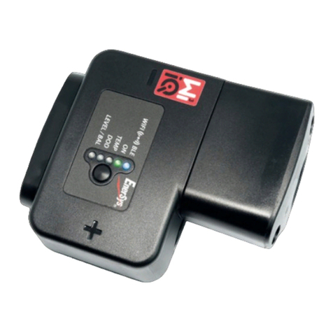
A) The Wi-iQ3 main unit
A Wi-iQ3 consists in:
• a core unit (for voltage measurement and communication features)
• a cable clamp (for mechanical fixation of DC cables)
• a current sensor (for current measurement)
• an option cover (for CA communication option)
The Wi-iQ3 can be assembled on industrial batteries from 24V to 80V (for other battery voltage please ask
your local rep.).
B) The Wi-iQ3 main unit with cable clamp (no current sensor)
There are two part-numbers depending on the DC cable gauge:
Product DC cable gauge designation
Wi-iQ3 16 > 50mm
2
Wi-iQ3 Core cables up to 50mm
2
70 > 120mm
2
Wi-iQ3 Core cables 70mm
2
to 120 mm
2
The difference is related to the cable clamp which fits to the cable gauge:
Clamp-1 (16 > 50mm
2
) Clamp-2 (70 > 120mm
2
)
NB : the cable clamp model number and the polarities are en raved in the plastic part.
Core unit
Cable clamp
Current
sensor
Option cover

WIIQ3 user Manual rev 05/2018
C) The Wi-iQ3 current sensors
There are three models of Hall Effect current sensor depending on the DC cable gauge and the battery
current rating.
Product DC
cable gauge*
Internal
diameter
Truc class
recommendation
Max
DC current
designation
Current
sensor
Up to 35mm
2
15.6mm Class 3 300A 35mm
2
& 300A max
Up to 120mm
2
25.2mm Class 1 and 2 600A 120mm
2
& 600A max
Up to 120mm
2
25.2mm Class 1 and 2 1000A 120mm
2
& 1000A max
* The DC cable au e does not take account of the terminals dimensions. Terminals may need to be
assembled after insertin the cable in the current sensor.
The Wi-iQ3 core unit is delivered with a protective plastic cover that needs to be removed to assemble
the selected current sensor.
D) The Wi-iQ3 installation
Follow carefully the installation procedure as described below.
1. Ma e sure the cables are not connected to the battery before proceeding to the assembly.
2. Remove the current sensor protective cover and the cable clamp from the main unit.
Caution: there is an O-ring seal between the Wi-iQ3 main unit and the protective cover. Ma e
sure the O-ring is still properly located in the main unit when assembling the current
sensor.
O-rin
Cable clamp
Protective
cover
Protective
cover
Current
sensor

WIIQ3 user Manual rev 05/2018
3. Insert the EGATIVE battery cable in the current sensor.
Caution: ma e sure to orientate properly the battery cable during assembly on the current
sensor (refer to the ID decal on the current sensor).
Input: 5V/ 25mA
Cur measure: ±300A
Model o.: WCS-3
Ref: 6LA20714
S/ : QZDA001254
Firmware: 1.0
-
Bat
ID decal of current sensor
4. Press the EGATIVE cable on the nails.
Caution:
the cable shall be pressed carefully against the nails perpendicularly to avoid bending the nails.
5. Assemble the current sensor on the main unit (torque 1.5 m ±0.1). Make sure to use the
appropriate screws (delivered with the current sensor).
Caution: using inappropriate screws (type and length) may damage the product and impact its
reliability.
Press carefully and perpendicularly
the cable on the nails
Current
sensor
14mm screws
Towards the battery
Towards the plu
The battery plu shall be
located on this side of the
sensor
The battery shall be located
on this side of the sensor

WIIQ3 user Manual rev 05/2018
6. Press the POSITIVE cable on the nails.
Caution: the cable shall be pressed carefully against the nails perpendicularly to avoid bending the nails.
7. Assemble the plastic clamp on the main unit (torque 1.5 m ±0.1) using 16mm length screws
Caution: using inappropriate screws (type and length) may damage the product and impact its
reliability.
8. Fasten the DC cables with cable ties at each side of the Wi-iQ3 to avoid stressing the connections
during handling.
16mm screws
Press carefully and perpendicularly
the cable on the nails

WIIQ3 user Manual rev 05/2018
9. The Wi-iQ3 main unit should be securely installed in order to avoid any shoc and misuse during
handling and operation.
10. As soon as supplying the Wi-iQ3 unit with the battery voltage, make sure that the LEDs lit according
to the initialization sequence:
• the BLE blue LED is lit during 7s,
• then all LEDs are blinking fast for few seconds.
E) The Wi-iQ3 LEDs
There are five LEDs on the Wi-iQ3 for status indication.
LED Color Lit Slow blin ing
(1s ON / 1s OFF)
Fast blin ing
(0.3s ON / 0.3s OFF)
Unlit
BLE
Green /A Paired
to a BLE sensor
Paired
to a BLE sensor
All LEDs blinking
fast during 10s
=
Identification
sequence
o BLE
communication
in progress
Blue /A Communicating in BLE
(E connect App) /A
O Green /A ormal status Communicating in Zigbee
(Wi-iQ Report) Misfunction
TEMP Red High
temperature /A /A ormal status
DOD Red Alert DOD Warning DOD /A ormal status
LEVEL/BAL Blue Low water
level Unbalance voltage /A ormal status
NB: - When the Wi-iQ3 is connected first to the battery volta e, the BLE blue LED is lit durin 7s then all
LEDs are blinkin fast for few seconds (initialization sequence).
- The button close to the LEDs has no function at this sta e.
F) The BLE peripheral sensors
A Wi-iQ3 can be associated to a peripheral sensor allowing battery temperature measurement, water
level and unbalanced voltage detections. Two main types of sensors are available depending on the
battery configuration:
• 2V sensors for assembly on 2V cells (with or without water level probe)
• 12V sensors for assembly on 12V blocs
Product Water level
probe
Temperature
probe
Unbalance
detection
designation
2V sensor Yes Yes Yes BLE T°/ LEV 2V (EMEA/ASIA)
o Yes Yes BLE T° 2V (EMEA/ASIA)
12V sensor o Yes Yes BLE T° 12V (EMEA/ASIA)
The sensors are communicating with Wi-iQ3 unit via Bluetooth Low Energy (BLE) process (they are also
called BLE sensors). The pairing process with a Wi-iQ3 unit is described in the Pairing section.

WIIQ3 user Manual rev 05/2018
G) The BLE peripheral sensors installation
The BLE sensors should be installed according to the sketches below.
• 2V cell setting:
The 2V sensor is connected to O E cell only (2V nominal voltage – red and black main supply wires). It
is recommended to install the BLE sensor on the middle of the battery. The 2V BLE sensor without
water level probe shall be secured on a harness through cable ties.
Caution: DO NOT CONNECT the sensor to more than ONE cell, a voltage above 4V would cause a
permanent product failure.
For connecting each wire on the battery, use only the genuine parts supplied with the BLE sensor:
• blac voltage tap for ANY wire
• heat-shrinkable crimping splice
Wire connection assembly details
NB: a BLE sensor includes its own protective fuse then the connection materials shall not include any
additional fuse.
Sensor with
water level probe
Sensor without
water level probe
Wire Function Length
Red POSITIVE volta e 300mm
Black (small) NEGATIVE volta e 300mm
Black (lar e) Temperature probe 300mm

WIIQ3 user Manual rev 05/2018
Unbalance detection is made by comparing the average cell voltage measured by the Wi-iQ3 with the
cell voltage measured by the BLE sensor. It is possible to deactivate the unbalance detection by
unticking the “Balance” selection box in the App or in Wi-iQ Report.
Caution: on BLE sensors with water level detection:
- the level probe shall be cut in order to be located 5mm above the separator and shall
not touch the separators or the internal cells plates.
- ma e sure that the level probe is fully protected by the plastic housing over its entire
length (no hole, no deformation) to avoid false detection.
• 12V bloc setting:
The 12V sensor is connected to O E bloc only (12V nominal voltage – red and black main supply
wires). The 12V BLE sensor shall be secured on a harness through cable ties.
Caution: DO NOT CONNECT the sensor to more than ONE bloc, a voltage above 24V would cause a
permanent product failure.
For connecting each wire on the battery, use only the genuine parts supplied with the BLE sensor:
• blac voltage tap for ANY wire
• heat-shrinkable crimping splice
Wire connection assembly details
NB: a BLE sensor includes its own protective fuses then the connection materials shall not include any
additional fuse.
Unbalance detection is made by comparing the average bloc voltage measured by the Wi-iQ3 with the
bloc voltage measured by the BLE sensor. It is possible to deactivate the unbalance detection by
unticking the “Balance” selection box in the App or in Wi-iQ Report.
H) The BLE sensors LEDs
There are two LEDs on the top of each sensor for status indication.
Color Lit Confidence blin ing
(every 32s)
Slow
blin ing
Alternate
blin ing
Unlit
Red High temperature /A Misfunction Identification
sequence
ormal
status
Blue Low water level ormal status
(unit in function) /A

WIIQ3 user Manual rev 05/2018
I) The Wi-iQ3 CAN option
It is possible to communicate with the Wi-iQ3 unit through CA communication protocol. It is done
through a CA option device which has to be connected to the Wi-iQ3.
The Wi-iQ3 main unit is delivered with a protective plastic cover that needs to be removed to
assemble the CA option.
1. Remove the current sensor protective cover from the main unit.
Caution: there is an O-ring seal between the Wi-iQ3 main unit and the protective cover. Ma e
sure the O-ring is still properly located in the main unit when assembling the current
sensor.
2. Assemble the CA option on the main unit (torque 1.5 m ±0.1). Make sure to use the appropriate
screws (delivered with the CA option).
Caution: using inappropriate screws (type and length) may damage the product and impact its
reliability.
Protective
cover
O-rin
14mm screws
CAN option

WIIQ3 user Manual rev 05/2018
3. The female connector pinout is described below.
4. A loose male connector is included in the option (ITT-CA O SURE-SEAL IP68 3-contact receptacle
with 2 pins and 1 socket adapted for 0.75-1.5mm
2
wires).
Product Receptacle
part number
Contact part number
Wire gauge Pin (qty 2) Soc et (qty 1)
ITT-CA O
SURE-SEAL
120-8551-001
(SS3R)
0.5–1.0mm
2
330-8672-001
(SS20)
031-8703-001
(SS20)
0.75–1.5mm
2
330-8672-000
(SS10)
031-8703-000
(SS10)
J) Communication / Download
There are two modes of communication available on the Wi-iQ3 device:
• Zigbee: this is the existing protocol already in use on Wi-iQ1 and Wi-iQ2 devices. It will continue
to provide communication to existing Life iQ chargers.
• BLE: this is a new feature which provides communication to a Smartphone.
The Wi-iQ3 can also be configured and provide data via Zigbee (Wi-iQ Report – v5.1.X minimum) or
BLE (E connect App).
K) “E connect” App
A Mobile App is developed for iOS and Android Smartphones. The App name is “E connect”
and will be available from App Store and Play Store. Access is protected by login/password.
Several access levels will be available through passwords.
The App is combining the existing COMpact App features (for on-board chargers) with the new Wi-iQ3
ones. This App requires to be connected to Internet (3G/4G or WIFI) to take advantage of full features.
This App allows mainly:
• to scan
1
and then associate the Wi-iQ3 to a customer site (list of devices is automatically
recorded on a remote server
2
)
• to set the Wi-iQ3 battery parameters (such as technology, capacity…)
• to download the Wi-iQ3 history data (data downloaded are automatically transferred to a
remote server* - there is no data stored on the Smartphone)
• to pair a Wi-iQ3 device with a BLE sensor
Notes: (1) When launchin the App, Bluetooth is automatically activated.
(2) If the Smartphone is not connected to Internet durin scan and data download, the transfer
to the remote server will be done as soon as the Internet connection is restored.
The main screens of the App with the main parameters are shown in the next pages.
CAN LOW CAN HIGH
GND
(optional)

WIIQ3 user Manual rev 05/2018
Customer pa e Scan pa e
Status pa e Status pa e (with low DOD)
Notes: (3) The ‘Share’ button allows to share the site data with another user (throu h his e-mail
address). By default, a customer site is only visible by its owner (who created it).
(4) The ‘Export’ button allows to export data in a .xrp file format which can be imported in the
Wi-iQ Report software for deeper analysis. A web link to download the file is provided or sent to
any user e-mail address.
(5) The ‘Open’ button allows to access to the list of devices already recorded in the customer site
in Off-line mode.
(6) The ‘Identification’ button allows to visually identify the selected device throu h the
identification sequence of its LEDs.
(7) As lon as the Wi-iQ3 is connected to the App, there is no communication with the BLE
sensor (i.e. temperature data is not refreshed).
Number of
char ers on site
(history)
Number of
Wi-iQ3 on site
(history)
Device selection filter
(
char ers, sensors, Wi-iQ3
)
Wi-iQ3 SOC
Char er
Warnin
Serial Number
MAC address
Real time data
(V, A, V/c,
remainin Ah)
Temperature
7
if
connected to a BLE
sensor
Cycles data
Warnin s Settin s (writtin is
pasword protected)
Battery ID
FW revision
Open
5
the site
without scannin the
devices
Scan the
devices on site
Export
4
Share
3
Device identification
6
Serial Number
MAC address
BLE sensor
Direct access
to a device
via QR code
Real time SOC
Warnin

WIIQ3 user Manual rev 05/2018
Status pa e (Off-line) Settin s pa e (1)
Settin s pa e (2) Settin s pa e (3)
Settin s pa e (4) Warnin pa e
Multiple graphs are available (SOC, temperature, Ah…) with various period filters (day, week, year).
L) Pairing a Wi-iQ3 with a BLE sensor.
The process to associate (i.e. to pair) a BLE sensor to a Wi-iQ3 unit is described below:
1. With the E connect Mobile App (using Bluetooth)
• After installing the Wi-iQ3 and BLE units on the battery
Battery technolo y
& capacity
Set to ON to
detect
unbalancin
Customer data
BLE pairin
Set Wi-iQ3 mode
Password
Nb of cells
Battery s/n
Warnin
Normal status
Off-line status when
displayin a Wi-iQ3 which
is out of ran e
Only settin s parameters
can be displayed
Set to ON if
connected to BLE
w/ level probe

WIIQ3 user Manual rev 05/2018
• Launch the Mobile App
• Scan the Wi-iQ3 units
• Access to the selected Wi-iQ3
• Enter in the Settings section
• Enter the password
• Scroll down to the BLE Sensor section
• Set the Sensor Active parameter to O
• Enter the BLE Sensor Address (MAC) – you can either fill it manually or read it via the BLE QR
code
ID decal on a BLE sensor
NB: how to et the BLE sensor address in case the decal is missin or not readable:
• Launch the SCAN process to detect the surroundin BLE sensors
• Activate the IDENTIFICATION mode of the detected sensors and identify the ri ht one
• Record its MAC address
To verify that pairing is effective, it is needed to disconnect the App from the BLE sensor then:
• Exit from the settings section and return to the SCA page (or Exit from the App)
• Check that the green BLE LED is blinking on the Wi-iQ3 (refer to section F)
2. With the Wi-iQ Report Software (using Zigbee dongle)
• After installing the Wi-iQ3 and BLE units on the battery
• Launch Wi-iQ Report with the USB dongle connected (v5.1.X minimum)
• Scan the Wi-iQ3 units
• Add and access to the selected Wi-iQ3
• Enter in the BLE section
• Tick the Active box
• Enter the BLE Sensor Address (MAC)
• Tick the appropriate boxes and set cells balance number depending on the BLE sensor model
• Click on Write
Enter the BLE sensor address
(MAC# on the BLE ID decal)
Set Sensor Active
to ON
Manual enter QR code readin
Save the chan e

WIIQ3 user Manual rev 05/2018
• Verify that pairing is effective by checking that the green BLE LED is blinking on the Wi-iQ3
(refer to section F)
M) Use conditions.
1. The Wi-IQ3 is a battery controller expected to be mounted on an industrial battery.
2. The assembly has to be made in a non-confined place.
3. Input Voltage range : [15Vdc ; 120Vdc]
4. Battery voltage: 24, 36, 48, 72, 80V (96/120V other WIIQ3 model)
5. Current measurement range: [+/-300A][+/-600A] [+/-1000A]
6. Temperature range: [0 ; 70°C]
7. Altitude < 2000m, Pollution level protection: 3 (dusty environment)
8. Measurement level: I (measures unconnected to network), do not use in level II,III,IV
9. Technical support: Refer to our website : www.enersys.com to find your local contact.
10. Standards:
* Radio Spectrum (Directive 2014/53/EU - RED )
* FCC ID: T7V4561HM (Panasonic industrial 802.14.4 modem – 2,405-2,475GHz )
* FCC ID: WAP2001 (Cypress BLE PRoC – 2,402-2.48GHz)
THIS DEVICE COMPLIES WITH PART 15 OF THE FCC RULES. OPERATIO IS SUBJECT TO THE FOLLOWI G TWO CO DITIO S: (1) THIS DEVICE MAY OT
CAUSE HARMFUL I TERFERE CE, A D (2) THIS DEVICE MUST ACCEPT A Y I TERFERE CE RECEIVED, I CLUDI G I TERFERE CE THAT MAY CAUSE
U DESIRED OPERATIO .
I ACCORDA CE WITH FCC REQUIREME TS, CHA GES OR MODIFICATIO S OT EXPRESSLY APPROVED BY E ERSYS COULD VOID THE USER'S AUTHORITY
TO OPERATE THIS PRODUCT.
Enter the BLE sensor address
(MAC# on the BLE ID decal) Tick the Active box
Tick the appropriate boxes
dependin on BLE model
Click on Write
Enter the number of cells
Other manuals for Wi-iQ3
1
Other EnerSys Measuring Instrument manuals
