enertik 100A User manual

Motive Charger
User Manual
Version: 1.1

Table of Contents
1. SAFETY INSTRUCTIONS..........................................................................................................................1
2. INSTALLATION ..........................................................................................................................................2
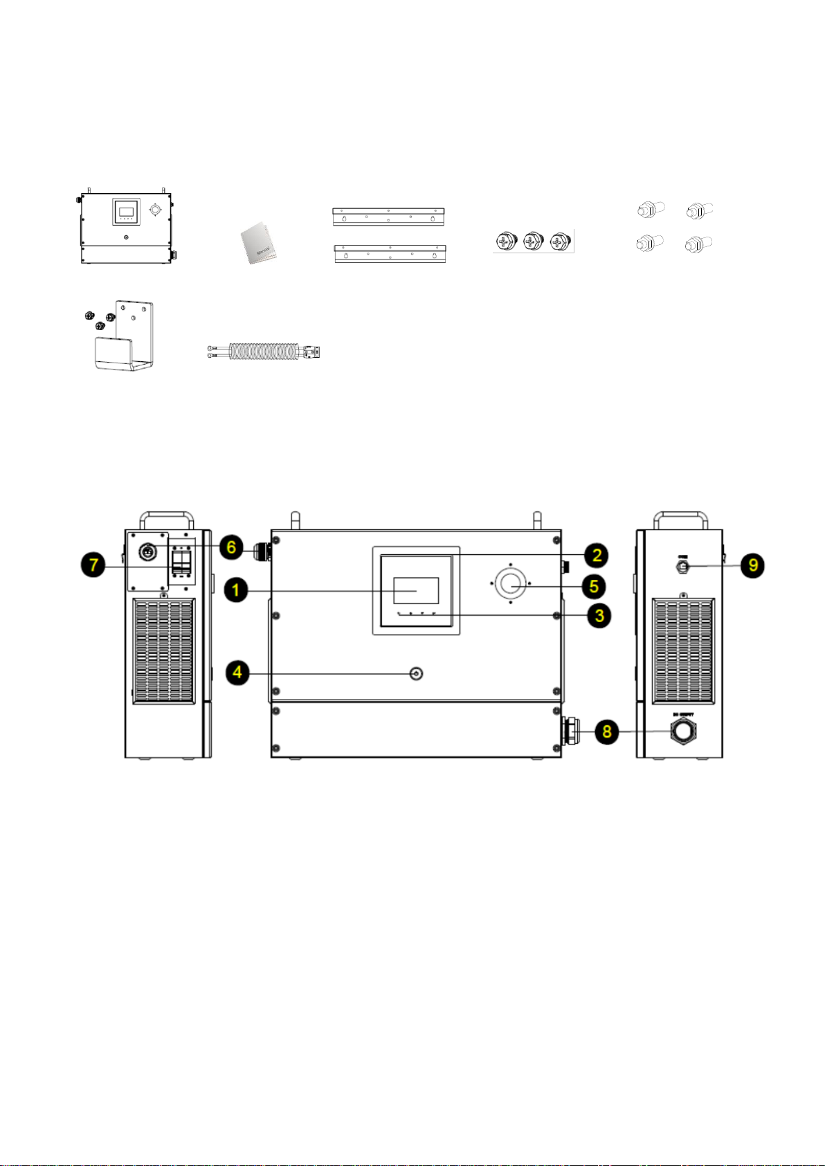
2.1 Unpacking and Inspection..................................................................................................................2
2.2 Product Overview...............................................................................................................................2
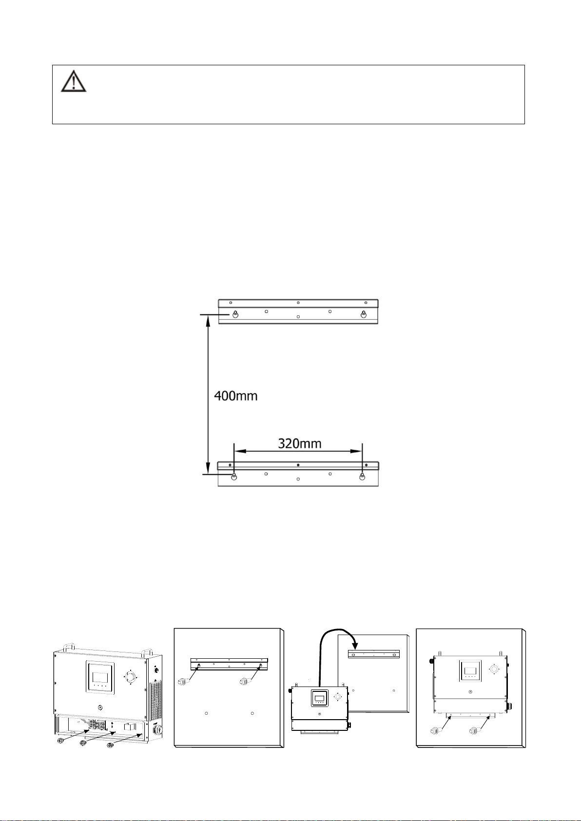
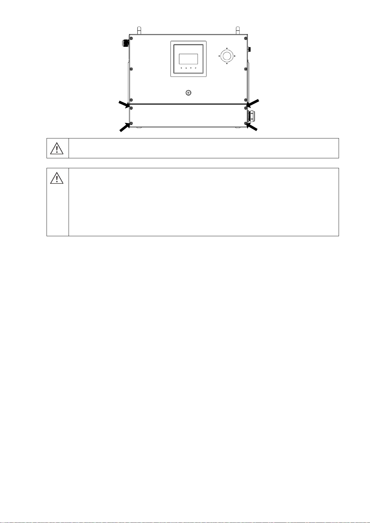
2.3 Mounting the Unit ...............................................................................................................................3
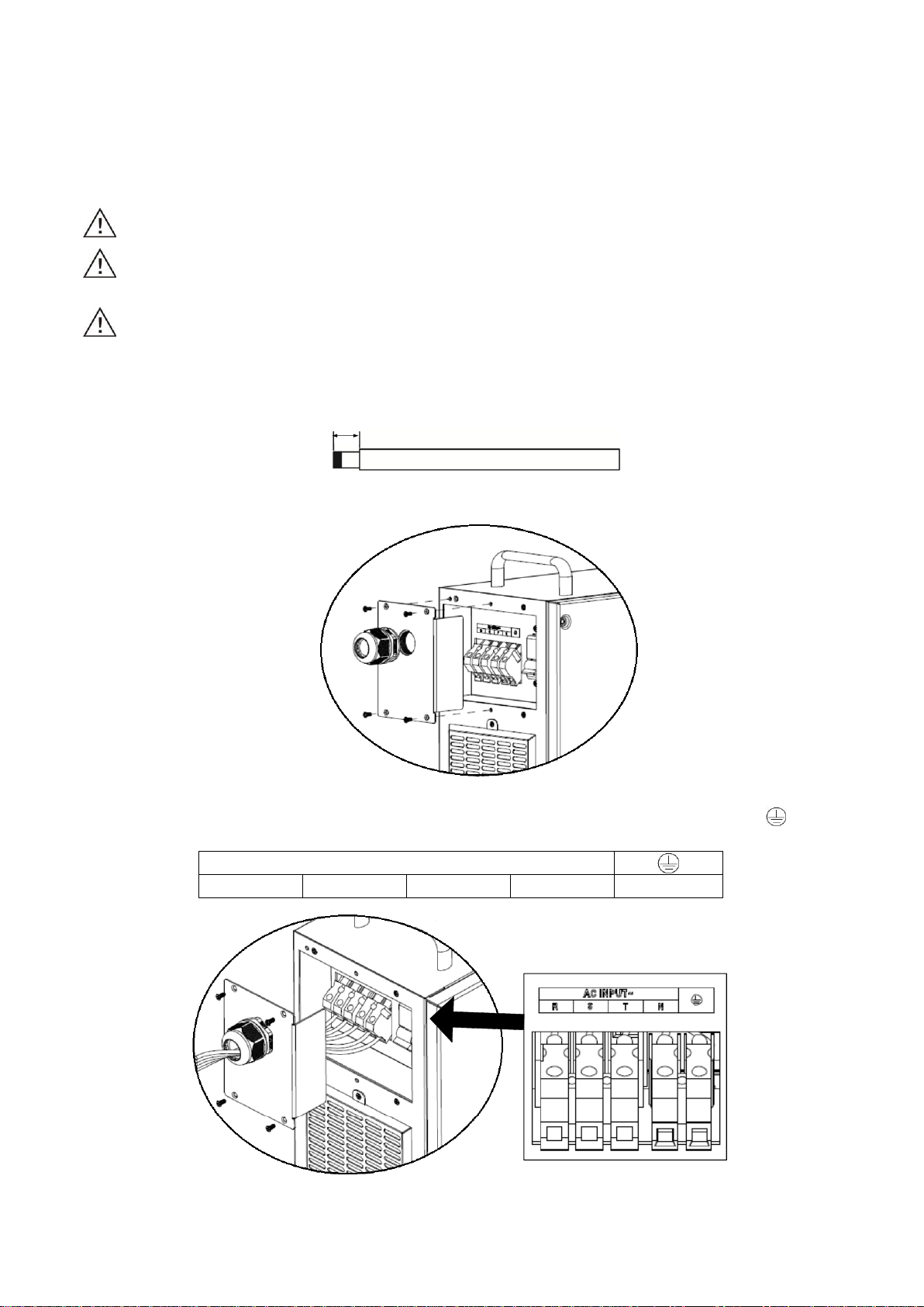
2.4 AC Input Connection ..........................................................................................................................4
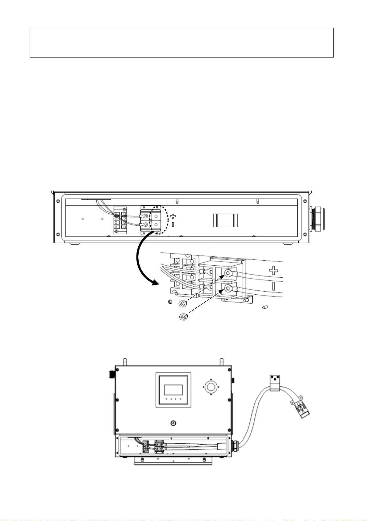
2.5 Battery Connection.............................................................................................................................5
3. OPERATION...............................................................................................................................................7
3.1 Power ON/OFF...................................................................................................................................7
3.2 Operation and Display Panel .............................................................................................................7
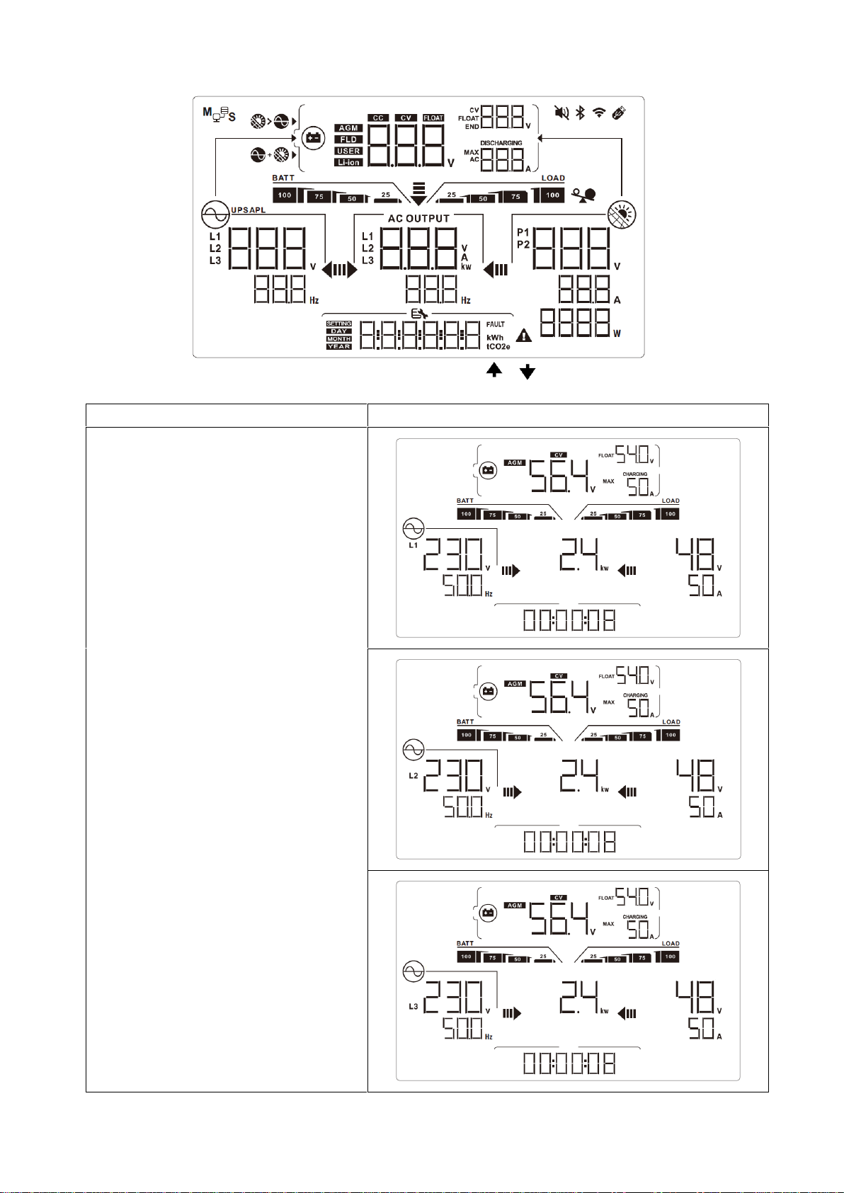
3.3 LCD Display .......................................................................................................................................8
3.4 LCD Setting......................................................................................................................................10
3.5 Fault Reference Code ......................................................................................................................16
3.6 Warning Indicator .............................................................................................................................18
4. TROUBLE SHOOTING ............................................................................................................................19
5. SPECIFICATIONS....................................................................................................................................21

1
1. SAFETY INSTRUCTIONS
Thanks for choosing our product, please read carefully the following user manual and the safety
instructions before installing the unit or using the unit! Keep this manual for future reference.
CAUTION –The batteries should be match with the voltage and current of this product to operate
charging.
Only qualified personnel can install this device with battery.
Do not disassemble the unit. Take it to a qualified service center when service or repair is required.
Incorrect re-assembly may result in a risk of electric shock or fire.
To reduce risk of electric shock, disconnect all wirings before attempting any maintenance or cleaning.
Turning off the unit will not reduce this risk.
Be very cautious when working with metal tools on or around batteries. A potential risk exists to drop
a tool to spark or short circuit batteries or other electrical parts and could cause an explosion.
NEVER cause AC output and DC input short circuited. Do NOT connect to the mains when DC input
short circuits.
Warning!! Only qualified service persons are able to service this device. If errors still persist after
following troubleshooting table, please send this battery charger back to local dealer or service center
for maintenance.

2
2. INSTALLATION
2.1 Unpacking and Inspection
Before installation, please inspect the unit. Be sure that nothing inside the package is damaged. You should
have received the following items inside of package:
Charger Unit Manual Mounting bracket x 2M5 screws x 3M10 expansion bolts x 4
U bracket DC cable
2.2 Product Overview
1. LCD display
2. RGB LED bar (refer to LCD setting section for the details)
3. Touchable function keys
4. Power on/off switch
5. Emergency power off device (EPO) button
6. AC input connectors
7. AC on/off breaker
8. DC output
9. Communication port

3
2.3 Mounting the Unit
1) Choose mounting location
Select an appropriate mounting location. Do not mount the battery charger on flammable construction
materials. Locate the unit on a vertical solid surface.
Note: Install this battery charger at eye level in order to allow the LCD display to be read at all times.
2) Check the clearance
Install the unit in a protected area that is free of excessive dust and has adequate air flow. For proper air
circulation to dissipate heat, allow a clearance of approx. 20 cm to the side and approx. 50 cm above and below
the unit. Do NOT operate it where the temperature and humidity is beyond the requirement. Check the
specification for the limitation.
3) Drill the holes
Drill Four holes in proper locations as following marked distance.
4) Mount the unit
Step 1: Remove the wiring cover of the unit. Fix one mounting bracket on the bottom of the charger with three
M5 screws.
Step 2: Use two M10 expansion bolts to fix another mounting bracket onto the mounting surface align with the
two holes drilled previously.
Step 3: Place the unit over the mounting bracket on the surface.
Step 4: Install the unit by screwing two M10 expansion bolts as shown in chart.
WARNING!! Remember that this battery charger is heavy so please be careful when removing it from the
package.
SUITABLE FOR MOUNTING ON CONCRETE OR OTHER NON-COMBUSTIBLE SURFACE ONLY.

4
2.4 AC Input Connection
CAUTION!! Before connecting to AC input power source, please install a separate AC breaker between the
unit and AC input power source. This will ensure the unit can be securely disconnected during maintenance and
fully protected from over current of AC input. The recommended spec of AC breaker is 100A.
WARNING! All wiring must be performed by a qualified personnel.
WARNING! It's very important for system safety and efficient operation to use appropriate cable for AC
input connection.
WARNING: Be sure that AC power source is disconnected before making AC input connection.
Please follow below steps to implement AC input connection:
1) The suggested cable for AC wires is 12 AWG. Remove insulation sleeve 18mm for five conductors of wires.
18
2) Disassemble the AC connector cover by removing 4 screws.
3) Insert AC input wires through the cable gland, then connect AC input wires according to polarities indicated
on terminal block and tighten the terminal screws. Be sure to connect PE protective conductor ( ) first.
Input Terminal
R
S
T
N
Ground
4) Make sure the wires are securely connected. Fix the AC connector cover with four screws.

5
2.5 Battery Connection
CAUTION: For safety operation and regulation compliance, it’s requested to install a separate DC over-current
protector or disconnect device between battery and battery charger. It may not be requested to have a
disconnect device in some applications, however, it’s still requested to have over-current protection installed.
WARNING! All wiring must be performed by a qualified personnel.
Please follow below steps to implement battery connection:
1) Losing two screws on battery terminals. Insert the ring terminal of battery cable flatly into battery
terminals of the unit and make sure the bolts are tightened with torque of 2.5-3 Nm. Make sure polarity at
both the battery and the unit are correctly connected and ring terminals are tightly screwed to the battery
terminals.
2) If it's necessary to hold battery cable, install U bracket properly.
3) Assemble the wiring cover to the unit with four screws.
CAUTION: Important
Be sure to connect AC wires with correct polarity. If wires are connected reversely, it may cause utility
short-circuited.

6
WARNING: Shock Hazard
Installation must be performed with care due to high battery voltage in series.
CAUTION!! Do not place anything between the flat part of the Battery Charger terminal and the
ring terminal. Otherwise, overheating may occur.
CAUTION!! Do not apply anti-oxidant substance on the terminals before terminals are
connected tightly.
CAUTION!! Before making the final DC connection or closing DC breaker/disconnector, be sure
positive (+) must be connected to positive (+) and negative (-) must be connected to negative
(-).

7
3. OPERATION
3.1 Power ON/OFF
Once the unit has been properly installed and the batteries are connected well, simply press On/Off switch
to turn on the unit.
3.2 Operation and Display Panel
The operation and display panel, shown in below chart, is on the front panel of the unit. It includes a LCD
display, four touchable function keys and RGB LED Bar, indicating the operating status and input/output
power information.
Touchable Function Keys
Function Key
Description
ESC
To exit setting mode
PREVIOUS
To go to previous selection
NEXT
To go to next selection
ENTER
To confirm the selection in setting mode or enter setting mode

8
3.3 LCD Display
The LCD display information will be switched in turns by pressing “ ” “ ” button. The selectable information
is switched as the following table in order.
Display Items
LCD Display
AC input voltage in L1 phase->AC input
voltage in L2 phase->AC input voltage in
L3 phase (three phase voltage display in
turns with 3s interval)
AC Input Frequency
Charger CV Voltage Charger Float Voltage
Maximum Charger Current
Battery Capacity
Charging Current Bar
Charging Voltage
Charging Current
Charging Watt
Charging Time
(Default Display Screen)

9
AC input voltage in L1 phase
AC Input Frequency
Charger CV Voltage Charger Float Voltage
Maximum Charger Current
Battery Capacity
Charging Current Bar
Charging Voltage
Charging Current
Charging Watt
CPU1 Firmware Version
AC input voltage in L1 phase
AC Input Frequency
Charger CV Voltage Charger Float Voltage
Maximum Charger Current
Battery Capacity
Charging Current Bar
Charging Voltage
Charging Current
Charging Watt
CPU2 Firmware Version
AC input voltage in L1 phase
AC Input Frequency
Charger CV Voltage Charger Float Voltage
Maximum Charger Current
Battery Capacity
Charging Current Bar
Charging Voltage
Charging Current
Charging Watt
CPU3 Firmware Version

10
3.4 LCD Setting
After pressing and holding “”button for 3 seconds, the unit will enter setting mode. Press “ ” or “”
button to select setting programs. And then, press “ ” button to confirm the selection or “ ” button to exit.
Setting Programs:
Program
Description
Selectable option
00
Exit setting mode
Escape
01
Charger
Enable/Disable
Charger Enable (default)
If selected, charger is on if AC
input normal.
Charger Disable
If selected, charger is always off
even AC input normal.
02
Battery Type Setting
AGM(default)
Flooded
If selected, the rated battery voltage (program 03) must select a
suitable option according to the actual rated of the battery voltage.
Meanwhile, the charging voltage (program 07 and program 08) will
be set to a specific value based on the program 03 settings.
User-Defined
If selected, charging voltage can
be set up in program 07 & 08.

11
02
Battery Type Setting
Li-ion
If selected, charging voltage can
be set up in program 07 & 08.
03
Rated Battery Voltage
48V (default)
60V
80V
100V
120V
Select a suitable option
according to the actual rated
battery voltage. Otherwise, the
battery may be over-charged or
no energy can be charged into
the battery.
04
Max Charging Current
10A
100A(default)
The setting range is from 10A to 100A. Increment of each click is
10A.
05
Charger stage
selection
Auto(default)
If selected, charger will do the
charging stage control
automatically according to the
actual battery voltage before
charging starts.

12
05
Charger stage
selection
2-Stage
If selected, charger will always
charge battery with 2-stage
(CC->Float).
3-Stage
If selected, charger will always
charge battery with 3-stage
(CC->CV->Float).
06
CV charging time
setting
Auto(Default)
If selected, the time for the
charger during CV stage is
controlled by the charger
automatically.
5min
If selected, the time for the
charger during CV stage will be
limited to setting value.
The setting range is from 5 min.
to 480 min.
480min

13
07
CV Charging Voltage
CV charging voltage in Program 07 may be different based on the
battery type selection in program 02 and battery voltage setting in
program 03.
If 48V is selected in program 03,
If AGM or Flooded is selected in
program 02, the CV charging
voltage is fixed in 56.4V.
If Self-defined or Li-ion is
selected in program 02, this
program can be set up. Setting
range is from 48.0V to 60.0V.
Increment of each click is 0.1V.
If 60V is selected in program 03,
If AGM or Flooded is selected in
program 02, the CV charging
voltage is fixed in 70.5V.
If Self-defined or Li-ion is
selected in program 02, this
program can be set up. Setting
range is from 60.0V to 75.0V,
increment of each click is 0.1V.
If 80V is selected in program 03,
If AGM or Flooded is selected in
program 02, the CV charging
voltage is fixed in 94.0V.
If Self-defined or Li-ion is
selected in program 02, this
program can be set up. Setting
range is from 80.0V to 100.0V,
increment of each click is 0.1V.
If 100V is selected in program 03,
If AGM or Flooded is selected in
program 02, the CV charging
voltage is fixed in 117.5V.
If Self-defined or Li-ion is
selected in program 02, this
program can be set up. Setting
range is from 100.0V to
119.2.0V, increment of each
click is 0.1V.
If 120V is selected in program 03,
No matter what option is
selected in program 02, the CV
charging voltage is fixed in
120.0V.

14
08
Floating Charging
Voltage
Floating charging voltage in Program 08 may be different based on
the battery type selection in program 02 and battery voltage setting
in program 03.
If 48V is selected in program 03,
If AGM or Flooded is selected in
program 02, the floating
charging voltage is fixed in
54.0V.
If Self-defined or Li-ion is
selected in program 02, this
program can be set up. Setting
range is from 48.0V to 60.0V,
increment of each click is 0.1V.
If 60V is selected in program 03,
If AGM or Flooded is selected in
program 02, the floating
charging voltage is fixed in
67.5V.
If Self-defined or Li-ion is
selected in program 02, this
program can be set up. Setting
range is from 60.0V to 75.0V,
increment of each click is 0.1V.
If 80V is selected in program 03,
If AGM or Flooded is selected in
program 02, the floating
charging voltage is fixed in
90.0V.
If Self-defined or Li-ion is
selected in program 02, this
program can be set up. Setting
range is from 80.0V to 100.0V,
increment of each click is 0.1V.
If 100V is selected in program 03,
If AGM or Flooded is selected in
program 02, the floating
charging voltage is fixed in
112.5V.
If Self-defined or Li-ion is
selected in program 02, this
program can be set up. Setting
range is from 100.0V to
119.2.0V, increment of each
click is 0.1V.
If 120V is selected in program 03,
No matter what option is
selected in program 02, the
floating charging voltage is fixed
in 120.0V.

15
09
Buzzer control
Buzzer on(Default)
Buzzer off
10
Backlight control
Backlight on(Default)
Backlight off
11
On/off control for RGB
LED
LED on(Default)
LED off
12
RGB LED effects
LED power solid on(Default)
LED power cycling

16
3.5 Fault Reference Code
Fault Code
Fault Event
Icon on
01
Bus soft start time out
02
Bus voltage over 460V
03
Bus voltage under
04
Bus voltage unbalance
06
AC input current over
07
AC input relay fail
08
PFC driver circuit stop working
09
Bus voltage over 470V
10
Bus voltage over 480V
11
AC input current unbalance
13
PFC can’t communicate with LLC
14
PFC NTC temperature sensor fail
15
DC output current sensor fail
16
DC output current peak over
17
LLC soft start time out
18
DC output voltage over
19
DC output voltage low
20
DC output short fault
21
LLC driver circuit stop working
22
PFC fault
23
DC output voltage over (rapid protection)

17
24
LLC NTC temperature sensor fail
25
DC output average voltage low 15V
26
DC output voltage over 120V
27
DC output short fault (rapid protection)
28
DC bus voltage over
29
Can’t charge battery
34
Output diode or fuse fault
65
LLC can’t communicate with PFC
66
DC output current over
71
Fan lock
72
AC contactor loss fault
73
DC contactor loss fault
74
Main switch fail or unit can’t detect the main switch signal
75
Communication between Panel and PFC/LLC module loss

18
3.6 Warning Indicator
Warning
Code
Warning Event
Audible Alarm
Icon flashing
01
AC input loss
Beep once every second
02
Communication between PFC and
LLC loss
Beep once every second
03
AC input voltage high
Beep once every second
04
AC input voltage low
Beep once every second
06
Communication between LLC and
PFC loss
Beep once every second
07
Temperature of internal circuit too
high
Beep once every second
08
LLC EEPROM fail
Beep once every second
09
DC output voltage low
Beep once every second
12
Fan lock
Beep once every second
13
Temperature of internal circuit high
Beep once every second
14
PFC EEPROM fail
Beep once every second
15
Environment temperature high
Beep once every second
16
Environment temperature too high
Beep once every second
17
Battery voltage and the charging
voltage setting not match
Beep once every second
18
Firmware version different for two
PFC/LLC modules inside for Auto
Mate-200A
Beep once every second
This manual suits for next models
1
Table of contents