Enertronica Santerno LT 1500V User manual


INSTALLATION, USE AND
MAINTENANCE
SUNWAY STRING BOX
LT 1500V 24 INPUTS
Rev. 02 - Error! Unknown document property
name.
2 / 43
•This manual is integrant and essential to the product. Carefully read the instructions contained herein
as they provide important hints for use and maintenance safety.
•This device is to be used only for the purposes it has been designed for. Other uses should be
considered improper and dangerous. The manufacturer is not responsible for possible damages caused
by improper, erroneous and irrational uses.
•Enertronica Santerno is responsible for the device in its original setting.
•Any changes to the structure or operating cycle of the device must be performed or authorized by
Enertronica Santerno.
•Enertronica Santerno assumes no responsibility for the consequences resulting by the use of non-
original spare-parts.
•Enertronica Santerno reserves the right to make any technical changes to this manual and to the device
without prior notice. If printing errors or similar are detected, the corrections will be included in the new
releases of the manual.
•The information contained herein is the property of Enertronica Santerno and cannot be reproduced.
Enertronica Santerno enforces its rights on the drawings and catalogues according to the law.
Enertronica Santerno S.p.A.
Via della Concia, 7 - 40023 Castel Guelfo (BO) Italy
Tel. +39 0542 489711 - Fax +39 0542 489722

INSTALLATION, USE AND
MAINTENANCE
SUNWAY STRING BOX
LT 1500V 24 INPUTS
Rev. 02 - Error! Unknown document property
name.
3 / 43
TABLE OF CONTENTS
1. GENERAL INFORMATION.....................................................................................7
1.1. SCOPE OF THIS MANUAL AND FOR WHOM THIS MANUAL IS INTENDED..................................7
1.2. SYMBOLS USED.................................................................................................................................7
1.3. DEFINITIONS.......................................................................................................................................7
1.4. SUNWAY STRING BOX LT 1500V......................................................................................................8
1.5. OPERATING PRINCIPLE ....................................................................................................................8
1.5.1. INTEGRATED STANDARD FUNCTIONS.................................................................................9
1.5.2. ATTACHED DOCUMENTATION.............................................................................................10
1.5.3. PRESERVATION OF THE DOCUMENTATION......................................................................10
2. CAUTION STATEMENTS.....................................................................................11
2.1. SAFETY RECOMMENDATIONS.......................................................................................................11
2.2. PRECAUTIONS FOR USE AND PROHIBITIONS.............................................................................11
2.3. INTENDED USE.................................................................................................................................12
2.4. QUALIFIED TECHNICAL PERSONNEL............................................................................................12
2.5. SPECIFIC DANGERS LINKED TO PHOTOVOLTAIC (PV) SYSTEMS............................................12
2.6. PERSONAL PROTECTIVE EQUIPMENT .........................................................................................12
2.7. EXECUTION OF WORK....................................................................................................................13
2.8. SAFETY PROCEDURE .....................................................................................................................14
2.8.1. POLYCARBONATE PROTECTIVE PANELS..........................................................................14
3. DESCRIPTION OF THE PRODUCT .....................................................................15
3.1. COMPOSITION OF THE SUNWAY STRING BOX LT......................................................................15
4. PRODUCT IDENTIFICATION ...............................................................................16
4.1. PRODUCT PART NUMBER ..............................................................................................................16
4.2.PRODUCT REVISION INDEX ...........................................................................................................16
4.3. SERIAL NUMBER..............................................................................................................................16
5. STORAGE AND TRANSPORT.............................................................................17
5.1. CHECKING THE PRODUCT ON DELIVERY....................................................................................17
5.2. CONDITIONS FOR TRANSPORT.....................................................................................................17
5.3. STORAGE..........................................................................................................................................17
6. HANDLING AND ASSEMBLY..............................................................................18
6.1. PRODUCT HANDLING......................................................................................................................18
6.2. MOUNTING THE PRODUCT ON THE INSTALLATION SITE..........................................................19
7. INSTALLATION AND COMMISSIONING.............................................................20
7.1. PRELIMINARY NOTES......................................................................................................................20
7.2. CONNECTION TO THE OUTPUT CABLES AND FUNCTIONAL EARTH........................................20
7.3. CONNECTING THE STRINGS..........................................................................................................22
7.4. REPLACING AND INSERTING THE STRING FUSES .....................................................................24
7.5. COMMISSIONING .............................................................................................................................25
7.6. NOTES ON OUTPUT SHORT-CIRCUIT ...........................................................................................25
8. MAINTENANCE....................................................................................................27
8.1. MAINTENANCE SHEET....................................................................................................................27

INSTALLATION, USE AND
MAINTENANCE
SUNWAY STRING BOX
LT 1500V 24 INPUTS
Rev. 02 - Error! Unknown document property
name.
4 / 43
8.1.1. BOX VISUAL INSPECTION AND CLEANING ........................................................................27
8.1.2. CHECKING THE CONNECTOR STATE (IF PRESENT) ........................................................28
8.1.3. CHECKING THE CABLE GLANDS STATE.............................................................................28
8.1.4. CHECK TUBING STATE .........................................................................................................28
8.1.5. CHECKING THE FUSES.........................................................................................................28
8.1.6. CHECKING THE SPDS...........................................................................................................28
8.1.7. CHECK CABLE TIGHTENING ................................................................................................28
9. UNINSTALLING....................................................................................................30
9.1. PRELIMINARY SAFETY PROCEDURES .........................................................................................30
9.2. UNINSTALLATION PROCEDURE ....................................................................................................30
10. TROUBLESHOOTING.......................................................................................... 32
10.1. GENERAL PRINCIPLES IN THE EVENT OF FAILURE ...................................................................32
10.1.1. FAULT CONTAINMENT......................................................................................................32
10.2. FAULT ANALYSIS .............................................................................................................................32
10.2.1. SPDS TRIPPED..................................................................................................................33
10.2.2. STRING FUSE BLOWN......................................................................................................33
10.3. DISCONNECTING A STRING...........................................................................................................33
10.4. HOW TO CONTACT THE CUSTOM SERVICE ................................................................................34
11. TECHNICAL DATA............................................................................................... 35
11.1. NAMEPLATE......................................................................................................................................35
11.2. ENVIRONMENTAL REQUIREMENTS FOR STORAGE AND TRANSPORT...................................35
11.3. INSTALLATION REQUIREMENTS....................................................................................................35
11.4. ELECTRICAL SPECIFICATIONS......................................................................................................36
11.4.1. CHOOSING THE STRING FUSE SIZE..............................................................................37
11.5. MECHANICAL SPECIFICATIONS.....................................................................................................37
11.5.1. MECHANICAL DIMENSIONS.............................................................................................38
11.5.2. CLEARANCE VALUES.......................................................................................................38
11.5.3. FASTENING THE BOX TO ITS SUPPORT STRUCTURE ................................................38
11.6. CONNECTIONS.................................................................................................................................38
11.6.1. DC CONNECTION –STRING CABLES.............................................................................39
11.6.2. DC CONNECTIONS - OUTPUT CABLES..........................................................................40
11.6.3. CONNECTION OF FUNCTIONAL EARTH CABLES .........................................................41
11.6.4. SPDS...................................................................................................................................41
12. ANNEX..................................................................................................................42
12.1. REVISION TABLE..............................................................................................................................42

INSTALLATION, USE AND
MAINTENANCE
SUNWAY STRING BOX
LT 1500V 24 INPUTS
Rev. 02 - Error! Unknown document property
name.
5 / 43
INDEX OF FIGURES
Figure 1: SUNWAY STRING BOX LT 1500V 24 INPUTS ............................................................................ 8
Figure 2: Block diagram of the first and second parallel levels..................................................................... 9
Figure 3: Single-line diagram of a SUNWAY STRING BOX LT.................................................................... 9
Figure 4: Position of the measurement points and of the screws to remove the polycarbonate cover panel
of output terminals....................................................................................................................................... 14
Figure 5: Internal view of a SUNWAY STRING BOX LT............................................................................. 15
Figure 6: SUNWAY STRING BOX LT 1500V Serial Number ..................................................................... 16
Figure 7: Packaging of the SUNWAY STRING BOX LT ............................................................................. 18
Figure 8: Unpacking the SUNWAY STRING BOX LT................................................................................. 19
Figure 9: Correct mounting.......................................................................................................................... 19
Figure 10: Incorrect mounting...................................................................................................................... 19
Figure 11: Removing the polycarbonate cover protecting the output cables and the functional earth ....... 21
Figure 12: Position of the output cable tubing and functional earth cable gland......................................... 21
Figure 13: Bottom side view and inside view with string inputs highlighted................................................ 23
Figure 14 Routing of cables inside the string box ....................................................................................... 24
Figure 15: String voltage measurement points............................................................................................ 25
Figure 16: Short-circuit located downstream from the SUNWAY STRING BOX LT 1500V........................ 26
Figure 17: Example of a typical Surge Protective Device (for reference only)............................................ 28
Figure 18: SUNWAY STRING BOX LT 1500V nameplate.......................................................................... 35
Figure 19 Mechanical dimension................................................................................................................. 38
Figure 20: Maximum dimensions of the cable lugs to be used for the output cables ................................. 41

INSTALLATION, USE AND
MAINTENANCE
SUNWAY STRING BOX
LT 1500V 24 INPUTS
Rev. 02 - Error! Unknown document property
name.
6 / 43
INDEX OF TABLES
Table 1: Documentation available for download from santerno.com.......................................................... 10
Table 2: Product name ................................................................................................................................ 16
Table 3: Key to the output cable and functional earth connections............................................................. 21
Table 4 Key to string connections ............................................................................................................... 23
Table 5: Maintenance sheet ........................................................................................................................ 27
Table 6: Environmental requirements for storage and transport................................................................. 35
Table 7: Installation requirements for SUNWAY STRING BOX LT 1500V ................................................. 36
Table 8 Electrical ratings ............................................................................................................................. 36
Table 9: Fuses recommended based on ISC................................................................................................ 37
Table 10: Dimensions and weight of the SUNWAY STRING BOX LT........................................................ 37
Table 11: Minimum clearance values.......................................................................................................... 38
Table 12: Inputs to be used based on the string current............................................................................. 39
Table 13: Power cables connection............................................................................................................. 40
Table 14: Functional earth cable................................................................................................................. 41
Table 15: SPDs technical specifications ..................................................................................................... 41

INSTALLATION, USE AND
MAINTENANCE
SUNWAY STRING BOX
LT 1500V 24 INPUTS
Rev. 02 - Error! Unknown document property
name.
7 / 43
1. GENERAL INFORMATION
1.1. Scope of this Manual and for Whom this Manual is Intended
This manual covers the following SUNWAY STRING BOX LT 1500V Class II models:
•SB-24-LT07-1500V –24 INPUTS 2 OUTPUTS PER POLE
•SB-24-LT08-1500V –24 INPUTS 1 OUTPUT PER POLE
•SB-24-LT10-1500V –24 INPUTS 1 OUTPUT PER POLE
This manual must be read by:
•Installers
•Operators
•Plant manager
•Please refer to section 0.
Images included in this manual are for reference only.
1.2. Symbols Used
Danger
Indicates an operating procedure which, if not carried out correctly, may lead
to injuries or even death caused by electric shock.
Warning
Indicates an operating procedure which, if not carried out correctly, may cause
serious damage to equipment.
Note
Indicates important information concerning use of the equipment.
Prohibition
Strictly forbids the execution of operating procedures.
1.3. Definitions
Installer
Technician responsible for setting up, positioning and installing the equipment in compliance with the system
diagram and in accordance with first-class, professional criteria.
Operator
Worker who has been suitably trained and informed on the risks and relative safety procedures to be
adopted. The operator can carry out routine maintenance on the equipment.
Plant manager
Person who co-ordinates or manages system management activities and is responsible for ensuring health
and safety standards are adhered to.
Technical room
Place used for housing the technological systems such as the wiring, plumbing, heating, air-conditioning,
lifting and telecommunications systems.
It is equipped with suitable forced-air ventilation and/or air conditioning and is also fitted with appropriate
safety devices governing access, maintenance and fire-prevention.
Person in charge of running the electrical system (System Manager)
Person with the highest level of responsibility concerning operation of the electrical system. If required some
of his/her tasks may be delegated to others.
Person in charge of working activities (Works Supervisor)

INSTALLATION, USE AND
MAINTENANCE
SUNWAY STRING BOX
LT 1500V 24 INPUTS
Rev. 02 - Error! Unknown document property
name.
8 / 43
Person with the highest level of responsibility concerning the execution of work. If required some of his/her
tasks may be delegated to others.
The Works Supervisor must give all persons involved in the execution of work activities the relative
instructions concerning reasonably foreseeable dangers which may not be immediately apparent.
Skilled electrician
Someone who has been trained and has enough technical knowledge or experience to enable him/her to
avoid the dangers which may be generated by electricity.
Instructed person
Someone who has been adequately advised or supervised by a skilled person to enable him/her to
avoid the dangers which may be generated by electricity.
1.4. SUNWAY STRING BOX LT 1500V
The SUNWAY STRING BOX LT 1500V products have been designed for maximum reliability and life
expectancy, based on numerous years of experience working with large ground and rooftop installations,
complies with the most stringent national and European safety directives.
Careful and precise design down to the very last detail and strict quality control guaranteed by standard ISO
9001 are the strong points of a reliable product which is able to maintain its features unaltered over time.
Designed to last in even the most arduous environmental conditions, Enertronica Santerno string boxes
guarantee wide safety margins during daily use.
These and other design features are what position SUNWAY STRING BOX LT 1500V at the highest level
of reliability and performance for photovoltaic field energy production.
Figure 1: SUNWAY STRING BOX LT 1500V 24 INPUTS
1.5. Operating Principle
Medium- and large-power PV generator systems are made up of a high number of strings. To optimize the
connection topology and enhance the protection and monitoring systems, the parallel connection of the
strings is usually carried out on more than one level, usually a first parallel level and a second parallel level.
Enertronica Santerno offers a complete range of products for string parallel connections, SUNWAY STRING
BOX LS, SUNWAY STRING BOX LT 1000V and SUNWAY STRING BOX LT 1500V for creating the first
parallel level and the Sunway DC-Parallel or inside the inverter for creating the second parallel level.

INSTALLATION, USE AND
MAINTENANCE
SUNWAY STRING BOX
LT 1500V 24 INPUTS
Rev. 02 - Error! Unknown document property
name.
9 / 43
Figure 2: Block diagram of the first and second parallel levels
The SUNWAY STRING BOX LT 1500V is made up of the following function blocks:
•String connection section, including:
oSafety fuses,
oParallel connection of the PV generator strings,
oSurge protection device (SPD,
•Output section, including:
oswitch disconnector.
Figure 3: Single-line diagram of a SUNWAY STRING BOX LT
1.5.1. Integrated Standard Functions
The main integrated standard functions of SUNWAY STRING BOX LT 1500V 24 INPUTS 2 OUTPUTS are
listed below:
•Possibility to connect up to 24 strings
•Fuses on both poles (fuses to be ordered separately).
•DC switch disconnector.
•Surge Protection Devices (SPDs).
INSTALLATION, USE AND
MAINTENANCE
SUNWAY STRING BOX
LT 1500V 24 INPUTS
Rev. 02 - Error! Unknown document property
name.
10 / 43
•Box made of self-extinguishing glass fiber reinforced polyester, UV resistant.
•IP65 degree of protection.
•Complete integration with the Sunway Station.
Note
The fuse kit is supplied separately.
1.5.2. Attached Documentation
Each SUNWAY STRING BOX LT 1500V is supplied with a leaflet including the basic safety instructions.
The following documents are available for download from santerno.com:
Name of the document
Scope
Installation Guide
Contains all the information necessary for the
assembly, installation and maintenance of the
product
Table 1: Documentation available for download from santerno.com
1.5.3. Preservation of the Documentation
All documents must be kept for the entire life span of the equipment together with the system documentation.
They must be kept in a place where they are readily available.

INSTALLATION, USE AND
MAINTENANCE
SUNWAY STRING BOX
LT 1500V 24 INPUTS
Rev. 02 - Error! Unknown document property
name.
11 / 43
2. CAUTION STATEMENTS
This section covers safety statements. The non-observance of the safety instructions below may cause
serious injury or death and equipment failure. Carefully read the instructions below before installing, starting
and operating the equipment.
Only competent personnel must carry out the equipment installation.
2.1. Safety recommendations
Note
Always read this instruction manual thoroughly before starting the equipment.
Danger
ALWAYS PROVIDE FUNCTIONAL EARTH BONDING.
OBSERVE THE PRESCRIPTIONS CONCERNING CONDUCTOR SECTION
INDICATED IN SECTION 11.6.3.
Warning
Do not connect supply voltages which exceed the rated voltage. If voltage
exceeding the rated value is applied, the internal circuits may be damaged.
Do not carry out isolation tests between the power terminals.
Make sure that the screws on the fuses have been tightened correctly.
Observe the ambient conditions for installation.
2.2. Precautions for Use and Prohibitions
Danger
RISK OF ELECTRIC SHOCK
NEVER carry out operations on the equipment when it is powered.
EXPLOSION AND FIRE RISKS
The risk of explosion or fire may exist if the equipment is installed in a room
containing flammable vapours. Do not install the equipment where there is a
risk of explosion or fire.
Prohibition
The product described in this manual has not been designed to operate in
potentially explosive atmospheres. Consequently, installation in such an
environment is strictly prohibited.
Prohibition
It is forbidden to make any technical or mechanical modifications to the
product even when out of warranty.
Enertronica Santerno is not responsible for any risks that may arise due to
unauthorised alterations, modifications or tampering. .

INSTALLATION, USE AND
MAINTENANCE
SUNWAY STRING BOX
LT 1500V 24 INPUTS
Rev. 02 - Error! Unknown document property
name.
12 / 43
Prohibition
It is strictly prohibited to operate inside the SUNWAY STRING BOX LT 1500V to
carry out short circuit tests concerning the strings.
Any system testing must be carried out on the individual strings only once that
have been disconnected from the product.
2.3. Intended Use
The SUNWAY STRING BOX LT 1500V products constitute a modular system for creating parallel strings
for PV modules.
The product envisages an output on-load disconnector which is capable of cutting off the connection of the
PV field subsection.
Observe the maximum operating voltage indicated in the product technical characteristics found in section
The product must only be used as prescribed in this manual. The DC power supply must come from the PV
field only.
Any use other than that described in this manual is to be considered inappropriate and therefore improper.
2.4. Qualified Technical Personnel
All work on SUNWAY STRING BOX LT 1500V products must be carried out by skilled technical personnel
only. By skilled personnel it is intended persons who have been suitably trained to carry out the work in
question.
To commission and use the SUNWAY STRING BOX LT, personnel must know and understand the
instructions for installation and use. In particular, all safety warnings must be strictly observed.
2.5. Specific Dangers Linked to Photovoltaic (PV) Systems
PV systems have certain characteristics which are the source of additional hazards and are described
below:
•A live current source is connected. Depending on the operating conditions, there may be live voltage
from the PV generator or from the electrical grid. This must be taken into consideration, particularly when
disconnecting parts from the system.
•Very high DC voltages are involved (with no periodic zero crossings) hence failure or the incorrect use
of fuses or plugs may cause electric arcs.
•The short-circuit current of the PV generator is only slightly higher than the maximum operating current
and furthermore is linked to radiation. This means that fuses may not always blow in the event of a short-
circuit.
•The PV generator grid is usually an IT type, i.e. it is only earthed in the event of a fault or energy leakage.
For connection to PV fields with earthing pole, connection is of the TN type, but the earth connection is
protected by a fuse which may trip in the event of a single fault.
•In the event of a fault (for example a short-circuit), cutting off a generator with a high number of branches
may prove to be somewhat difficult. Take great care to ensure each sub-field disconnect switch has been
opened before going near the devices installed in the technical room.
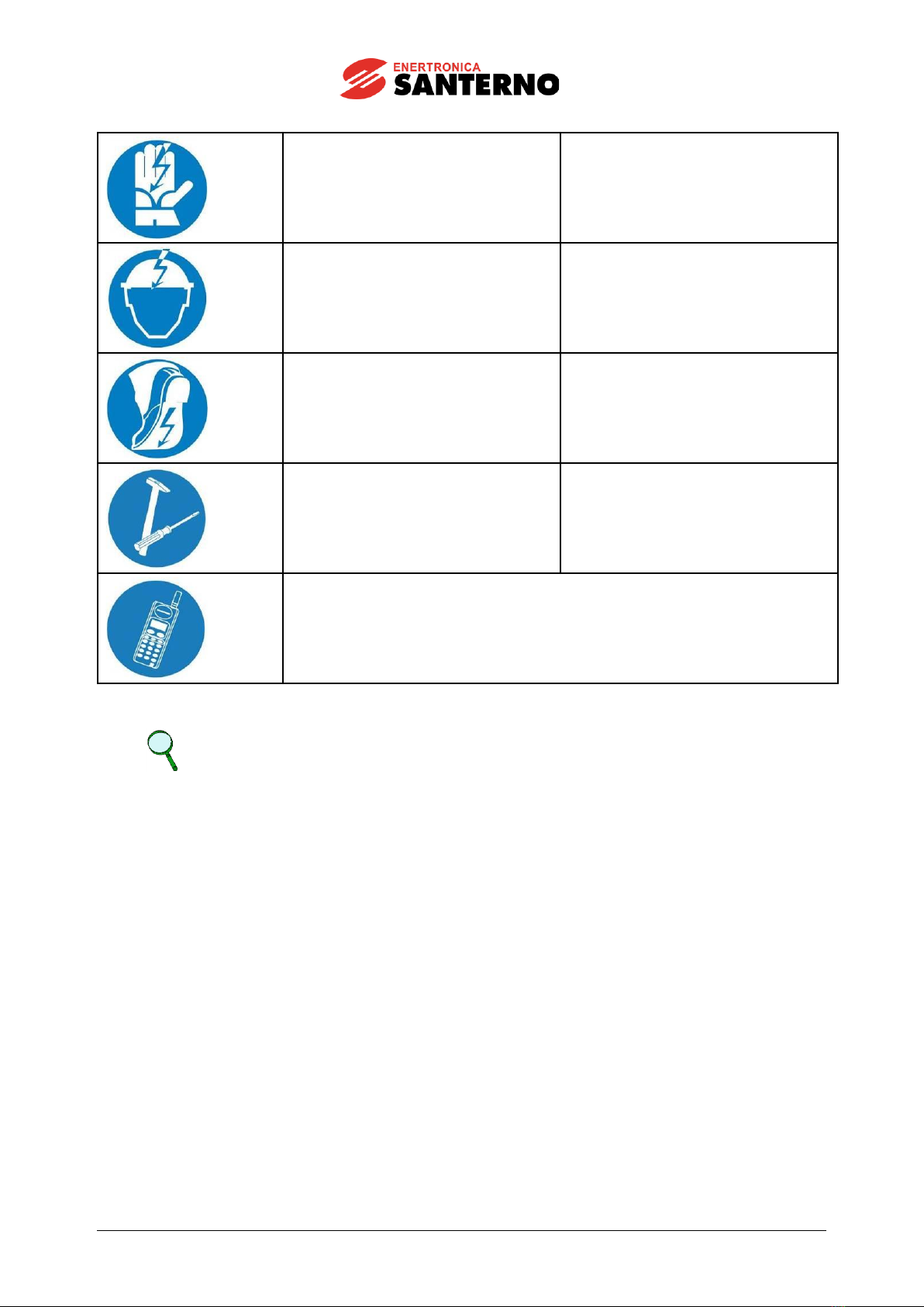
2.6. Personal Protective Equipment
Maintenance technicians must be provided with the following personal protective equipment as envisaged
by European Directives and relative implementation of the same on national territory.
SYMBOL
DESCRIPTION
Safety glasses/face shield
Throughout operations
INSTALLATION, USE AND
MAINTENANCE
SUNWAY STRING BOX
LT 1500V 24 INPUTS
Rev. 02 - Error! Unknown document property
name.
13 / 43
1000 V high-voltage insulated gloves
Throughout operations
Dielectric helmet
Throughout operations
Safety footwear/dielectric boots
Throughout operations
Insulated tools
Throughout operations
Operators must also be provided with a suitable means of communication for
contacting the emergency services if necessary.
Note
It is always advisable to work on the electrical cabinets with THE POWER SUPPLY
SWITCHED OFF and the equipment in safety conditions (please refer to section 2.8).
2.7. Execution of Work
Maintenance, configuration modifications and management operations require the involvement of all
production and maintenance personnel. These activities must be carried out in observance of health
and safety regulations.
The Standards and Laws governing this aspect vary depending on the personnel involved, methods of
access and/or the tasks which may be carried out on the product and envisage constructive measures aimed
at guaranteeing adequate levels of safety.
Standard EN 50110-1, second edition, identifies the people who are granted access to the product:
•Person in charge of running the electrical system (System Manager).
•Person in charge of work activities (Works Supervisor).
•Skilled electrician.
•Instructed person.
Please refer to section 0.
Standard EN 50110-1 governs the way work in a plant is carried out and the relationship between the
aforementioned persons who may work on the plant to maintain the electrical safety conditions stipulated
by European Directives.
This standard and its national equivalents must therefore be adhered to whenever it is necessary to access
a PV system.
INSTALLATION, USE AND
MAINTENANCE
SUNWAY STRING BOX
LT 1500V 24 INPUTS
Rev. 02 - Error! Unknown document property
name.
14 / 43
2.8. Safety Procedure
Always place the equipment in safety conditions before carrying out any kind of operation inside the box
involving removing the polycarbonate protective panels providing IP20 degree of protection with respect to
live parts, even when the box front cover is open. To do this, follow the instructions provided below:
•Make sure that the inverter connected to the SUNWAY STRING BOX LT 1500V is not running, i.e. that
it is STOPPED.
•Open the inverter DC-side switch disconnector.
•Open the disconnector, if present, of all the string boxes connected to the same inverter.
•Open the cover of the SUNWAY STRING BOX LT 1500V and open the switch disconnector (there is NO
need to remove the polycarbonate safety panel).
•Open all fuses.
•Remove the polycarbonate protective cover and use a multimeter to check that voltage is not present
between the output bars polarities, among the poles and the earth.
•Proceed with the operation in question.
Danger
ELECTRIC SHOCK HAZARD
High voltage on string cables and output cables.
2.8.1. Polycarbonate Protective Panels
The SUNWAY STRING BOX LT 1500V is fitted with an internal polycarbonate protective panel. Live parts
which are most exposed to possible inadvertent contact are protected by this panel made of polycarbonate,
a transparent, break-proof material which is resistant to high temperatures. Once the front door has been
opened, the panel makes it possible to carry out the following operations in relative safety:
•visually inspect the box inside in relative safety:
•turning the DC switch ON or OFF;
•replace string fuses;
•measure string voltages.
Only during installation must be removed the cover panel of the output terminals following the instructions
given in the paragraph 7.2.
Prohibition
It is not necessary to remove the internal panel when commissioning and
maintaining the product. .
Figure 4: Position of the measurement points and of the screws to remove the polycarbonate cover panel of output
terminals

INSTALLATION, USE AND
MAINTENANCE
SUNWAY STRING BOX
LT 1500V 24 INPUTS
Rev. 02 - Error! Unknown document property
name.
15 / 43
3. DESCRIPTION OF THE PRODUCT
3.1. Composition of the SUNWAY STRING BOX LT
The product comprises:
•fuses on the string inputs of the positive pole
•fuses on the string inputs of the negative pole
•a surge protection device (SPD)
•switch disconnector
Figure 5: Internal view of a SUNWAY STRING BOX LT

INSTALLATION, USE AND
MAINTENANCE
SUNWAY STRING BOX
LT 1500V 24 INPUTS
Rev. 02 - Error! Unknown document property
name.
16 / 43
4. PRODUCT IDENTIFICATION
4.1. Product Part Number
The product Part Number identifies the parallel string box and is indicated on the relevant nameplate. The
nameplate also holds all the necessary technical data (please refer to section 11.1).
The product Part Number is made up of the following elements:
XX-YY-VVWW-ZZZZV-II
Field
Name
Description
XX
Model
SB: for STRING BOX
YY
N. of strings
N. of string inputs
VV
Version
LT: light
WW
Optional field
Identifies product versions
ZZZZ
Field voltage
1500: Class 1500V
II
Insulation class
If not present: Insulation class I
II: Insulation class II
Table 2: Product name
Example: SB-24-LT07-1500V-II
4.2. Product Revision Index
The product revision index is indicated on the nameplate. Please refer to section 11.1.
4.3. Serial Number
The serial number of each individual module can be found on the lower section of the module itself (on the
label and on the inside).
Figure 6: SUNWAY STRING BOX LT 1500V Serial Number
SN YYXXXXX
Where YY = year of manufacture of the string box
XXXXX = serial number

INSTALLATION, USE AND
MAINTENANCE
SUNWAY STRING BOX
LT 1500V 24 INPUTS
Rev. 02 - Error! Unknown document property
name.
17 / 43
5. STORAGE AND TRANSPORT
The warranty covers manufacturing defects. The manufacturer shall not be held liable for any damage which
may have occurred during transport and unpacking. Under no circumstances shall the manufacturer be held
liable for damage or faults caused by incorrect use, misuse, incorrect installation or inadequate temperature
or humidity conditions or exposure to corrosives nor for faults caused by operation outside the rated values.
Nor shall the manufacturer be held liable for consequential or accidental damage.
Note
For the terms of warranty, please refer to the warranty certificate supplied with the
product.
5.1. Checking the Product on Delivery
On receiving delivery of the equipment make sure that the packaging shows no signs of damage. Check
that it complies with your order by referring to the nameplates described below. In the event of any damage,
please contact the relative insurance company or the supplier. If the delivery does not match your order,
contact the supplier immediately.
Note
Check that all relative accompanying materials are present.
5.2. Conditions for Transport
The parallel string boxes are delivered packed to extremely high standards.
To avoid damaging the product, move the package using a pallet jack or a forklift with adequate lifting
capacity.
5.3. Storage
If the equipment is to be stored before installation, make sure that the ambient conditions in the warehouse
meet the necessary specifications (please refer to section 11.2).

INSTALLATION, USE AND
MAINTENANCE
SUNWAY STRING BOX
LT 1500V 24 INPUTS
Rev. 02 - Error! Unknown document property
name.
18 / 43
6. HANDLING AND ASSEMBLY
Prohibition
It is strictly forbidden to proceed with product handling and assembly
operations in adverse weather conditions, in snow, rain or persistent fog.
Always check that there is no water or condensate inside the product.
It is strictly prohibited to leave the product outside when its front cover is open,
in any kind of weather conditions.
Warning
The SUNWAY STRING BOX LT 1500V must be installed with the cable
input/output side pointing downwards.
Avoid installing the product where it may be exposed to direct sunlight.
Do not install the SUNWAY STRING BOX LT 1500V upside down or with its front
cover turned upwards. Make sure that air can circulate freely around the box.
Warning
Every time the SUNWAY STRING BOX LT 1500V is opened and reclosed, it must
be done to the highest working standards, ensuring that the product remains
intact and that no damage is caused to the sealing and fixing elements. Before
reclosing the front cover, always check that the inside of the SUNWAY STRING
BOX LT 1500V is free from condensate or water residues; if this is not the case
the product must be placed in safety conditions (please refer to section 2.8) and
thoroughly dried out. Make sure that the front cover is properly tightened and
that the correct degree of watertightness and IP rating (IP65) is restored. .
6.1. Product Handling
Remove the product from the packaging through the sides, keeping it horizontal to the ground.
Figure 7: Packaging of the SUNWAY STRING BOX LT

INSTALLATION, USE AND
MAINTENANCE
SUNWAY STRING BOX
LT 1500V 24 INPUTS
Rev. 02 - Error! Unknown document property
name.
19 / 43
Figure 8: Unpacking the SUNWAY STRING BOX LT
Make sure that the front cover is closed when handling the product. Avoid twisting, bumping or dropping the
product. Avoid any mechanical stress.
Note
The key to open the front cover is fastened externally to the string box connectors
The packaging may be different from what is reported in Figure 10.
6.2. Mounting the Product on the Installation Site
Warning
Being as the ambient conditions significantly affect the life-expectancy of the
product, do not install it where water build-up may be created due to dips in the
installation surface or where it may be exposed to constant dripping.
All the parallel string boxes must be installed in upright position as shown in Figure 9. To facilitate installation,
the parallel string boxes come supplied with special brackets.
To allow for easy installation and effective air circulation, make sure that there is enough free space around
the equipment.
Dimensions, weight and necessary clearance are indicated in section 11.5.
Figure 9: Correct mounting
Figure 10: Incorrect mounting

INSTALLATION, USE AND
MAINTENANCE
SUNWAY STRING BOX
LT 1500V 24 INPUTS
Rev. 02 - Error! Unknown document property
name.
20 / 43
7. INSTALLATION AND COMMISSIONING
7.1. Preliminary Notes
Warning
To carry out the following operations, check that the parallel string box is in
safety conditions. Please refer to section 2.8.
The following paragraphs provide information on power and signal cable connection and commissioning.
Each string must be made up of the same number of panels. All panels must have the same nominal
characteristics. Failure to observe these specifications will lead to a plant with low performance and possible
malfunctions.
Do not install devices and/or components (SPDs, return or switch terminals, joins on the cables) on the
wiring between the SUNWAY STRING BOX LT 1500V and the modules. As well as lowering the level of
plant safety and performance, malfunctions may occur.
Danger
Before carrying out the electrical installation, make sure that the following
conditions are met:
All switches of the other string boxes connected to the same inverter are open,
No string fuse is inserted.
Follow the sequence below for the electrical installation:
•Connection of the output cable and functional earth bonding
•Connection of the strings
Electricians must wear personal protective equipment.
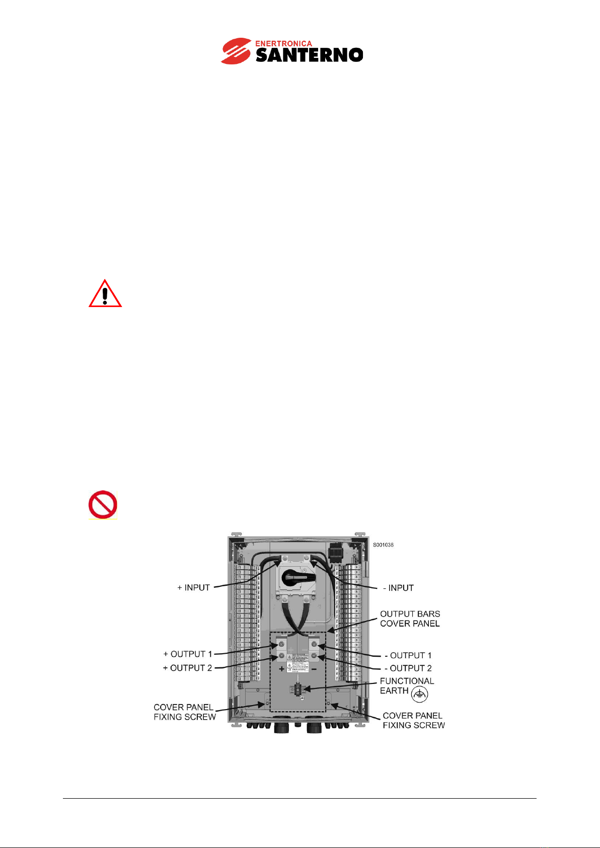
7.2. Connection to the output cables and functional earth
Note
Some models may be connected to two output cables per pole. In this case connect
first the lower cable for maximum ease of installation.
Proceed as follows:
•Remove the polycarbonate panel by only loosening the two M8 screws and by slightly pulling down the
panel since the head of the screws can pass through the holes on the panel. Then remove the panel
(Figure 11).
•With a tester check that no voltage is applied between the output bars and between each output bar and
the earth bonding.
•Insert the power cables already provided with cables lugs and spiral sheath, inside the string box by
letting the cable go through the coupling device of the protective spiral sheath (Figure 12).
•Connect the cables to the + and - bars in accordance with Table 10.
•Fasten the tubing to the tubing joints, making sure that IP65 degree of protection is not affected.
•Insert the functional earth cable through the dedicated cable-gland (Figure 12).
•Connect the functional earth cable to the relative terminal.
•Tighten the cable-gland, making sure that IP65 degree of protection is not affected.
•Reassemble the polycarbonate protective cover and tighten the two M8 screws.
Table of contents
Other Enertronica Santerno Network Hardware manuals


Popular Network Hardware manuals by other brands


D-Link
D-Link DNS-120 - NAS Server - USB product manual

Carrier
Carrier 40VMW005 Installation and maintenance instructions

Moxa Technologies
Moxa Technologies MRC-1002 Series Easy setup guide

Tellabs
Tellabs FlexSym OLT6 installation guide

Jetter
Jetter JX3-BN-EC user manual

AVYCON
AVYCON DIVERSITY user manual