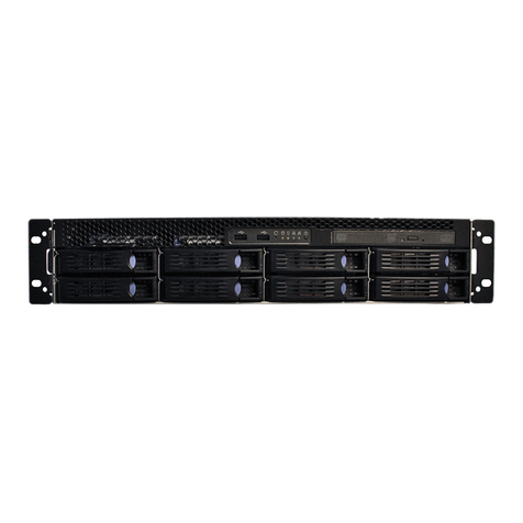
Tellabs FlexSym OLT6 User manual

Copyright © 2021 Tellabs®All Rights Reserved
OLT6 and 1134 Description Installation and Turnup Guide

OLT6 and 1134 Description Installation and Turnup Guide
Page 2 of 50
Tellabs®Information
Copyright
Copyright © 2021 Tellabs Enterprise, Inc. All rights reserved.
The information in this publication is proprietary to Tellabs Enterprise, Inc.
No part of this publication may be used, disclosed, reproduced, adapted, translated, stored in a
retrieval system, or transmitted in any form or by any means, electronic or mechanical, for any
purpose, without the written permission of Tellabs Enterprise, Inc. Although every precaution
has been taken in the preparation of this publication, Tellabs Enterprise, Inc. assumes no (i)
responsibility for errors or omissions contained herein or (ii) liability for any damages resulting
from the use of information contained herein. Information in this publication is subject to change
without notice.
Trademarks
The following trademarks and service marks are owned by Tellabs Operations, Inc. or its
affiliates in the United States and/or other countries: TELLABS®, TELLABS and Tsymbol®,
Tsymbol®.
Any other company or product names may be trademarks of their respective companies.
Proprietary
This document is the property of Tellabs Enterprise, Inc. and contains confidential and
proprietary information owned by Tellabs Enterprise, Inc. Any copying, use, or disclosure of the
contents of this document, without the written permission of Tellabs Enterprise, Inc., is strictly
prohibited.

OLT6 and 1134 Description Installation and Turnup Guide
Page 3 of 50
Table of Contents
Tellabs® Information......................................................................................................2
Copyright...................................................................................................................................2
Trademarks............................................................................................................................... 2
Proprietary................................................................................................................................ 2
1. Tellabs® 1134/OLT6 Optical Line Terminal Description, Installation, and Turn
Up Guide......................................................................................................................... 4
1.1. Description.........................................................................................................................5
1.2. Safety Precautions............................................................................................................ 8
1.3. Site Preparation............................................................................................................... 10
1.4. Installation........................................................................................................................18
1.4.1. Inspect OLT Chassis................................................................................................................ 19
1.4.2. Shelf Installation and Grounding.............................................................................................. 20
1.4.3. AC Power Installation............................................................................................................... 22
1.4.4. DC Power Installation...............................................................................................................26
1.4.5. Install Optical Fan Assembly.................................................................................................... 28
1.4.6. Card Installation....................................................................................................................... 32
1.4.7. Splitter Installation.................................................................................................................... 36
1.5. OLT Turnup.......................................................................................................................38
1.6. Add OLT to Panorama PON............................................................................................ 45
1.7. Contact Us........................................................................................................................49

OLT6 and 1134 Description Installation and Turnup Guide
Page 4 of 50
1. Tellabs® 1134/OLT6 Optical Line Terminal
Description, Installation, and Turn Up Guide
This document provides instructions to install and turnup the Tellabs® FlexSym OLT6
optical line terminal and the Tellabs® FlexSym OLT 1134. These two OLTs only differ
by the backplane capacity of the shelf. The two shelves are identical in installation
practices, line cards supported, and troubleshooting practices. This document covers
the installation of both the AC and 48VDC versions of the shelf.
Document Revisions
Revision
Date
Notes
A
May
2014
Document describes the AC and DC powered version of the shelf.
B
Dec
2015
Document includes instructions for the new TurNup Wizard commands and includes
ESU32, in addition to ESU30, to support SR29.0, Rev B.
C
Aug
2021
Addition of OLT6 to document and convert to web access.
Related Documentation
Document
Description
Comments
76.1100CIGSR291 B
Tellabs 1100 Series Optical LAN
Managing the PON Users Guide
Explains how to manage the system via the
Panorama PON OLAN management software.
76.PPONISAGSR31
Tellabs 1100 Series Optical LAN
Craft User Interface Guide
Explains the use of CLI.
76.PPON1100SR300
A
Panorama PON Installation and
System Administrators Guide
Explains setup and IT maintenance of the
Panorama PON OLAN management software.

OLT6 and 1134 Description Installation and Turnup Guide
Page 5 of 50
1.1. Description
Overview
OLT6 Shelf with Cover On
OLT6 Shelf with Cover Off
The Tellabs® FlexSym OLT6 and the Tellabs® FlexSym OLT 1134 are Optical Line
Terminals in the Tellabs family of OLAN PON products. The Tellabs FlexSym® Optical
Line Terminal Six (OLT6) and Tellabs® FlexSym OLT 1134 distribution shelves are
designed for mid-size and larger enterprise deployments. The Tellabs FlexSym® Optical

OLT6 and 1134 Description Installation and Turnup Guide
Page 6 of 50
Line Terminal Six (OLT6) and Tellabs® FlexSym OLT 1134 are scalable for enterprise
Optical LAN support of G-PON 2.5G, symmetrical XGS-PON 10G. The Tellabs FlexSym
OLT6 shelf is ideal for space-challenged installations in data centers, communications
closets and outdoor remote cabinets. It has redundant power rectifiers integrated with
the distribution shelf, resulting in faster installations. By integrating the power
rectification, the time and material needed to install this distribution shelf are
significantly reduced. Just like all other Tellabs OLT distribution shelves, the Tellabs
OLT6 leverages common software and common service cards. The OLT6 can be
equipped with the Ethernet Switch Unit Thirty-Two (ESU32) for wide area network
connectivity.
Features
The OLT 1134 and OLT6 support the following features:
·4 Generic PON Card I/O Slots supporting:
oUp to 32 PON interfaces and up to 2,048 ONTs with OIU8
oUp to 16 PON interfaces and up to 1,024 ONTs with QOIU7
·Support for both QOIU7 and OIU8 service cards
·OLT6 backplane supports 80 Gbps per multiservice slot
·1134 backplane supports 20 Gbps per multiservice slot
·Ideal for G-PON 2.5G, XGS-PON 10G and future NG-PON2 40G
·48GbE in network connectivity (with redundant ESU32 or ESU321)
·Redundant power utilizing either two 48VDC rectifier inputs or two 120VAC
inputs.
·Redundant Uplink and switching cards when equipped with a dual ESU32/321
switch card.

OLT6 and 1134 Description Installation and Turnup Guide
Page 7 of 50
·OLT6 can be mounted in both outdoor and indoor environments including space
challenged data centers, communications closets and outdoor remote cabinets.
It supports mounting via either 19" or 23" bracket options.
·Redundant fan units located in OFA (optical fan assembly)
Components
The OLT6/1134 Installation consists of the following components.
·OLT6/1134 OLT shelf with rack mount kit
·OFA1 - Optical Fan Assembly
·For AC Installs, OLT6/1134 Power Supply
·Power and Grounding Cable Assembly

OLT6 and 1134 Description Installation and Turnup Guide
Page 8 of 50
1.2. Safety Precautions
General Precautions
·Read this manual, in its entirety, prior to installing the device.
·Observe all warnings and cautions mentioned in this manual.
·Keep the device dry, ventilated, and clean.
·During severe weather conditions, unplug all electrical connections to the device
to protect against lightning surges.
·Keep the ventilation openings clean to ensure proper airflow and prolong the life
of the device.
·ONTs should not be opened.There are no user-serviceable parts in the device.
Product installation should only be performed by trained service personnel.
Do not bend the fiber optic cable to a diameter smaller than 7.5cm/3 inches. Doing so
may damage the fiber or prevent the signal from passing through properly.
Laser Safety
Danger! Personnel handling fiber optic cables must be trained for laser safety.
Danger! Optical Fibers emit invisible laser radiation. Avoid direct exposure to the
beam. Never look into the end of a Fiber or into a Fiber connector on a cable or a
device. Permanent eye damage or blindness can occur quickly from laser radiation.
Electrical Safety
Danger! Do not open the enclosure unless directed to do so by Tellabs technical
support. Doing so is dangerous and voids the warranty.

OLT6 and 1134 Description Installation and Turnup Guide
Page 9 of 50
·Check that the DC power supply polarity is correct. The system will not be
damaged by reversed polarity but will not operate until the polarity is corrected.
·Do not install electrical equipment in wet or damp conditions.
·Ensure that the power source for the system is adequately rated to assure safe
operation and provides current overload protection.
·Do not allow anything to rest on the power cable, and do not place this product
where people can stand or walk on the power cable.
Product Disposal
The Waste Electrical and Electronic Equipment (WEEE) symbol (shown below) will
accompany products that must be collected and disposed of separately from household
waste. The black bar under the symbol signifies the product was placed on the market
after August 13, 2005.
WEEE Product Disposal Symbol
Items such as integrated batteries can be disposed of along with the product; they will
be separated at recycling centers. By participating in the separate collection of identified
products, you will help with the correct disposal of these items and contribute to the
ongoing protection of our environment and human health.

OLT6 and 1134 Description Installation and Turnup Guide
Page 10 of 50
1.3. Site Preparation
Power Considerations
Prior to beginning the installation, ensure that the following power related items are
considered:
1. Verify that proper ground connections are available for correct terminal
operation.
2. Verify that the power outlet connector type matches the power cable end ordered
with the OLT.
3. Verify that any UPS systems being used are installed and operating correctly.
4. If power redundancy is being used, ensure both feed circuits are operational.
5. 48VDC Powering: Verify that suitably rated branch circuit breakers and/or fuse
positions are available in a locally installed DC Rectifier shelf when using 48VDC
powering. Breakers and fuses must be rated 15 Amps and be suitable for branch
protection.
Power Availability
When the equipment is being installed, ensure that there is an available 100/240 VAC
outlet within six feet of the unit. If the OLTis to operate in redundant supply mode, two
100/240 VAC outlets, on different feed circuits, should be within six feet of the unit.
Facility Grounding
Ensure that the facility grounding system is installed in accordance with EIA/TIA-607
Grounding and Bonding Requirements for Telecommunications in Commercial Building
United States Department of Agriculture Rural Utilities Service (RUS) Bulletin 1751F-
810, and/or local practices, as applicable.

OLT6 and 1134 Description Installation and Turnup Guide
Page 11 of 50
It is important that the shelf hasa solid ground for both safety and signal integrity of the
system. Ensure that the shelf is properly grounded per the standards cited above and
the installation guidance given in this document.
Racks and Cable Management
The OLT6/OLT1134 is designed to be mounted in a 19 inch equipment rack or in a 23
inch equipment rack if the optional 23 inch rack mounting kit was procured. It is
recommended that sufficient overhead cable trays and rack mounted cable
management are also installed to accommodate both fiber and metallic cabling.
1. Verify the rack that the chassis is to be installed in is properly installed and
grounded.
2. Verify that overhead cable trays have been installed for the new equipment.
3. Verify that rack mounted cable management been installed for the new
equipment. For horizontal cable management installed in the rack, it is
recommended that cable management is installed directly above and below the
OLT6 to allow the PON cables and the uplink cables to be trained separately.
4. It is recommended that vertical cable management is installed in the rack to
provide support for the PON and uplink cables.
Required Equipment
Ensure that all components required to install and turn-up the OLT are available.
Depending on the options chosen, the following is a checklist ofcomponents that should
be available:
·OLT6/OLT1134 Chassis
·OFA1 Fan Tray
·1st AC-DC Rectifier module

OLT6 and 1134 Description Installation and Turnup Guide
Page 12 of 50
·2nd AC-DC Rectifier module if configured with a 2nd rectifier
·Power cords with the appropriate connector
·23" Rack mounting kit if required
·Rack screws/clips
·ESU32 Switching Unit
·OIU8 PON card(s)
·Uplink SFPs and XFPs per the configuration
·PON XFPs per the configuration
Tools Required
Installation of the OLT6/OLT1134 will require the following tools:
·Laptop Computer: A laptop computer is required for turnup of the OLT-mini and
proper configuration of the uplink interfaces.
·Serial Cable: Initial turnup of the 1134 or OLT6 shelf will require a serial cable to
set the IP address and initial uplink settings.
You will need a terminal program to access the serial interface of the OLT if you use
the μUSB interface. Teraterm and putty are good open source options. Teraterm is
used for the examples in this document.
·SFP or XFP Uplink Modules: Information is given below for supported uplink XFP
10G and SFP 1G lasers compatible with the system.
You will need an SSHv2 terminal program if using SSHv2 to access the CLI for
ongoing maintenance of the system. Teraterm and putty are good open source
options.
·Power Wiring: If using the 48VDC powering option, you will need power wiring to
wire between the shelf and rectifier.

OLT6 and 1134 Description Installation and Turnup Guide
Page 13 of 50
·PON Lasers: Ensure you have purchased the appropriate Tellabs supported
PON Optical Modules shown in the "OLT Laser Part Numbers" table shown
below.
OLT Part Numbers
OLT6 AC Part Numbers
Description
Quantity Required
81.11S-OLT6
OLT6 AC Shelf
1
81.11P-1134ACPW-R6
OLT6 AC Power supply module
1 or 2(redundant)
81.11W-PC-C13-B-R6
Three prong AC power cord.
1 or 2(redundant)
Power and Digital Ground Cable Assembly
1
81.4115094FS
OFA1 Fan Assembly
1
Laser Part Numbers
Laser modules for the PONs and Uplinks must be purchased separately. The OLT-mini
comes equipped with no laser modules.
Both PON lasers in the OLT-mini must be of the same type, i.e. both GPON, or both
XGS-PON.
OLT Laser Part
Number
Laser Description
Distance
Connector
Comments
128211
850nm 1G SX SFP
550m
MMF
2xLC
Short Range 1G
Laser
4195098
XFP, TDM, 10Gbps, 1310nm,
industrial temp 5/3.3/1.8V;
10 Km
2xLC
XFP 10km Laser
81.11T-S1GB40KM-
R6
1310 1G LR SFP
40km SMF
2xLC
Long Range 1G
Laser
C.11T-
S1GBELX1131S
1310 1G LR SFP
10km SMF
2xLC
Long Range 1G
Wideband Laser
C11T-
S1GBER450030
Copper1G SFP
100m
RJ45
Copper 1G SFP

OLT6 and 1134 Description Installation and Turnup Guide
Page 14 of 50
C.11T-
XO192SR1851M
XFP: 10G, SX, 850NM, MM
100m
2xLC
10G Multimode XFP
C.11T-
XO192IR21550
10GBASE-ER/OC-192 IR-2
Multi-rate 40km Industrial Temp
XFP
40km
2xLC
10G 40km XFP
81.11T-XFPGPON-IT
Tellabs GPON Laser
20km
1xSC
UPC(blue)
2.5/1.25G Bidi
GPON Laser
81.11T-XFPXGSPON
Tellabs XGS-PON Laser
20km
1xSC
UPC(blue)
10G/10G Bidi XGS-
PON Laser
Power Requirements
The 1134/OLT6 has the following AC power requirements when powered by AC:
AC Power Specifications
Value
Comments
AC Input Voltage
100-240VAC
AC Input Line Frequency
50-60Hz (nominal)
AC Current Rating
5A@100VAC,
2.5A@240VAC
Max AC Input Power
600 W
The 1134/OLT6 has the following DC power requirements when powered by DC:
DC Power Specifications
Value
Comment
DC Input Voltage
-42.5 to -56VDC
DC Current Rating
14A @ 42.5VDC
DC Power
600W
Note: This device complies with Part 15 of the FCC Rules. Operation is subject to the
following two conditions: (1) this device may not cause harmful interference, and (2)
this device must accept any interference received, including interference that may
cause undesired operation.
The following table lists the power draw per installed card type.

OLT6 and 1134 Description Installation and Turnup Guide
Page 15 of 50
Card Type
Power Draw (Watts)
Ethernet Switch Unit (ESU30)
30
Ethernet Switch Unit (ESU32)
35
Quad-port Optical Interface Unit (QOIU7)
65
8 Port Optical Interface Unit (OIU8)
135
Note: The 1134 shelf does not have a power on/off switch as it is not intended to
power down the shelf while it is in service. All cards and the fan module are ‘hot
inserted’ i.e. can be replaced with the power on. This is part of the redundancy design
and ensures continued service while replacing cards or the fan module.
Physical Specifications
Value
Comments
Weight
28lb/12.7kg
Depth
16 in/40.64cm
Width
19in/43.18cm
Height
6 in/15.24cm
Environmental Specifications
Value
Comments
Temperature
-40°F/-40°C to +158°F/+70°C
Relative Humidity
5% to 95% noncondensing
Altitude
-220ft/-61m to +10,000ft/+3km
Fan
950CFM integrated with horizontal discharge
Airflow is left to right.
Compliance

OLT6 and 1134 Description Installation and Turnup Guide
Page 16 of 50
Compliance
Value
Comments
CE
-40°F/-40°C to +158°F/+70°C
UL
5% to 95% noncondensing
FCC
-220ft/-61m to +10,000ft/+3km
NEBS
950CFM integrated with horizontal discharge
Installation Considerations
When selecting the installation rack and its location the following items should be
considered as part of that selection:
·Elevated Operating Ambient - If installed in a closed or multi-unit rack assembly,
the operating ambient temperature of the rack environment may be greater than
room ambient. Therefore, consideration should be given to installing the
Tellabs® 1134/OLT6 in an environment compatible with the maximum operating
temperature specified “Specifications”.
·Reduced Air Flow - Installation of the Tellabs® 1134/OLT6 in a rack should be
such that the amount of air flow required for safe operation of the equipment is
not compromised. Ensure that air inlet and outlet are not blocked which could
lead to overheating of the shelf.
·Mechanical Loading - Mounting of the Tellabs® 1134/OLT6 in the rack should be
such that a hazardous condition is not achieved due to uneven mechanical
loading.
·Circuit Overloading - Consideration should be given to the connection of the
equipment to the supply circuit and the effect that overloading of the circuits
might have on overcurrent protection and supply wiring. Appropriate
consideration of the Tellabs® 1134/OLT6 nameplate ratings should be used
when addressing this concern.
·Redundant Power Inputs - It is an important consideration to ensure separate AC
or DC power inputs on different circuits for maximum survivability and

OLT6 and 1134 Description Installation and Turnup Guide
Page 17 of 50
redundancy. This ensures that failure of a single circuit or tripping of the circuit
breaker does not take down the system.
·Reliable Earthing - Reliable earthing when rack-mounting the Tellabs®
1134/OLT6 should be maintained. Particular attention should be given to supply
connections other than direct connections to the branch circuit (e.g. use of power
strips).
Figure 1: 19-in Tellabs® 1134/OLT6 Optical Line Terminal
Note: Shelf extensions are required if the Tellabs® OLT6 shelf is to be installed in a
23-inch rack and must be ordered separately

OLT6 and 1134 Description Installation and Turnup Guide
Page 18 of 50
1.4. Installation
Installation Overview
Installation will require the following steps:
·Inspection of the Chassis for Installation Damage
·Shelf Installation and Grounding
·AC Power Supply Installation or DC power install
·Installation of OFA
·OLT Card Installation
·Optical Splitter Installation

OLT6 and 1134 Description Installation and Turnup Guide
Page 19 of 50
1.4.1. Inspect OLT Chassis
1. Locate the packagecontaining the OLT chassis.
2. Open thepackageand examine the OLTfor any apparent damage.
3. If damage is noted, do not proceed and contact your Tellabssales representative
for a replacement unit.
4. See the section Contact Us for information on contacting TAC and warranty
information.

OLT6 and 1134 Description Installation and Turnup Guide
Page 20 of 50
1.4.2. Shelf Installation and Grounding
1. If the rack to be installed into is a 23" rack, the 23" rack mounting kit will be
required.
a. Remove the existing 19" rack mounting brackets from the OLT.
b. Attach the 23" rack mounting brackets.
2. The OLT chassis requires 4 rack units of space (7"). Insert the chassis into the
desired position in the rack until the mounting brackets are flush against the
mounting rails.
3. Secure the shelf with four rack screws. Insert the two upper mounting screws first
but do not tighten. Insert the two remaining screws into the bottom mounting
holes and tighten as required. Tighten the two upper mounting screws to ensure
the shelf is secure.
4. Secure the shelf with four #12-24 screws. Insert the two upper mounting screws
first. Do not tighten the mounting screws prior to inserting the lower mounting
screws as some play is typically needed to properly align all four holes.
5. Insert the remaining two screws into the bottom mounting holes and tighten as
required. Tighten the two upper mounting screws to ensure the shelf is secure.
6. Chassis ground connections are:
a. For AC powered systems, the primary ground is through thethird prong
ofin the AC power cord(s) for the shelf.
b. For both AC and DC systems there is a green and yellow supplemental
chassis ground wire on the right side of the chassis that must be
connected. This wire should be connected to a good earth ground
connection to ensure proper safety in the event of a short and to give the
shelf good immunity to interference from RF noise sources. Typically this
is done by deburring the paint from the rack using a grinding tool, then
connecting the ground wire to the bay frame using a standard rack screw.
Not removing the paint on the rack connection typically will give a poor
ground connection. The rack is typically grounded giving thesystem a
This manual suits for next models
1
Table of contents
Other Tellabs Network Hardware manuals
Tellabs
Tellabs 8820 MSR User guide

Tellabs
Tellabs 7100 Operating and maintenance instructions

Tellabs
Tellabs 251 User manual

Tellabs
Tellabs 100 Series User manual

Tellabs
Tellabs FlexSym OLT-mini User manual

Tellabs
Tellabs 263DC User manual

Tellabs
Tellabs 6047 User manual

Tellabs
Tellabs ONT180C User manual

Tellabs
Tellabs FlexSym ONT205 User manual
Popular Network Hardware manuals by other brands

Foxconn
Foxconn RAID 91-187C51GME0-00 user guide

Bosch
Bosch VIPX1A Quick installation guide

Paradyne
Paradyne COMSPHERE 3550 Series installation instructions

Ruijie
Ruijie RG-EST350 Series Hardware installation and reference guide

Panasonic
Panasonic KX-HTS Series quick start guide

Embin
Embin ETM 121 user manual