enervent Fenix 60 User manual
FENIX
PLANNING, INSTALLATION AND
OPERATION INSTRUCTIONS
Kipinätie 1, 06150 BORGÅ FINLAND
Phone +358 207 528 800, fax +358 207 528 844
www.enervent.fi
2006_1
2
OVERVIEW
MODEL
Before you begin reading, confirm the model of your appliance.
These instructions cover the following models:
Fenix 60
Fenix 85
Fenix 120
____________________________________________________________
EXPLANATION OF THE MARKS AND NUMBERS
60 Fan efficiency 105 W
85 Fan efficiency 130 W
120 Fan efficiency 185 W
All models are equipped with a built-in electrical heater 1000 W.
On all models the duct connections are Ø 160 mm.
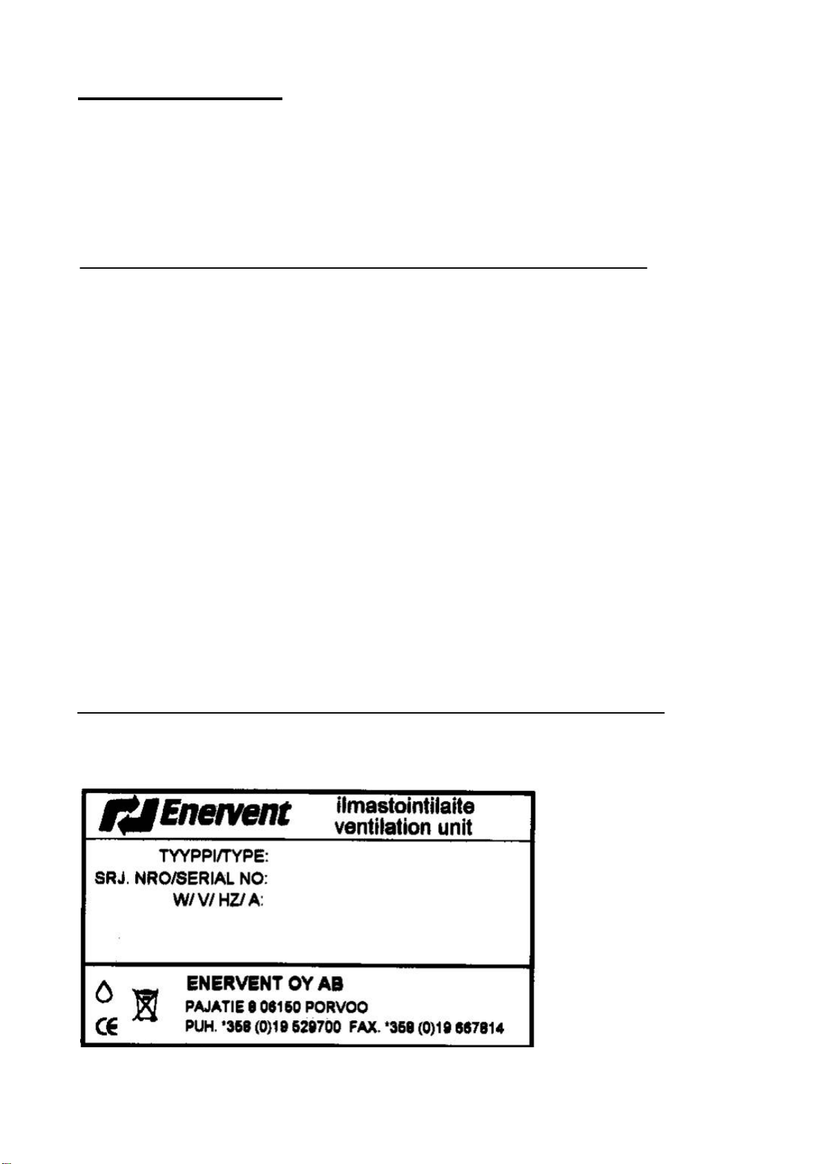
Inside the air handling unit there is a sticker with the model details . Fill in below this data
to have it for future reference e.g when you require spare filters.

3
INTRODUCTION
All Fenix ventilation units have been designed for continuous year round use. In Finland
the Enervent appliances have been installed in small premises and detached houses for
over 20 years. The popularity of the appliances is increasing year by year. Using
knowledge gained over the years, it has been possible to make the Fenix range more and
more user-friendly.
The Fenix range is the result of long-term product development. It is extremely versatile
and variable.
With the help of this manual it is possible to install the Fenix unit with common functions
yourself. We recommend that installation of ventilation units with special functions and
extra equipment be carried out by a qualified electrictian.
If in doubt, we recommend that a qualified ventilation engineer performs the installation
work.
Before any maintenance on the appliance is carried out, please read the warning on the
next page!
GU AR AN TE E
Enervent Oy Ab provides a two (2) year product guarantee on the Fenix range. The
guarantee covers the repair work with the necessary spare parts. Repair work will be
carried out at the factory premises in Porvoo, Finland or as agreed.
The guarantee is not valid if the unit has been incorrectly installed, poorly maintained or
mechanical damage has resulted from improper use. This guarantee does not
compensate for losses indirectly caused by the use of the appliance, troubleshooting,
reinstallation after the repair or transportation.
Retain the receipt as proof of purchase, and for the start date of the guarantee period.

4
TABLE OF CONTENTS
OVERVIEW.......................................................................................................2
MODEL .........................................................................................................................2
EXPLANATION OF THE MARKS AND NUMBERS.....................................................2
INTRODUCTION...........................................................................................................3
G UAR A NTE E ................................................................................................................3
TABLE OF CONTENTS................................................................................................4
WARNING.....................................................................................................................5
OPERATING PRINCIPLE.............................................................................................5
PLANNING........................................................................................................6
PLANNING OF THE DUCT SYSTEM...........................................................................6
EXHAUST AIR CLASSIFICATION OF LIVING AREAS...............................................8
TARGET VALUES FOR AIR FLOWS...........................................................................9
KITCHEN VENTILATION..............................................................................................9
INSTALLATION........................................................................................10
INSTALLATION PARTS.............................................................................................10
STANDARD PARTS .........................................................................................10
EXTRA EQUIPMENT........................................................................................10
ADDITIONAL EQUIPMENT ..............................................................................10
INSTALLATION..........................................................................................................11
FENIX DIMENSION DRAWING (WALL MOUNTING), LEFT HANDED.....................13
FENIX DIMENSION DRAWING (CEILING MOUNTING), LEFT HANDED.................15
CHANGING THE HANDEDNESS...............................................................................16
HEAT INSULATION OF THE DUCT SYSTEM...........................................................18
OPERATION..................................................................................................19
MAINTENANCE..........................................................................................20
TO BE OBSERVED DURING OPERATION...............................................................21
HEAT RECOVERY EFFICIENCY ...............................................................................21
FAILURE SEARCH AND TROUBLE SHOOTING......................................................22
TECHNICALDATA................................................................................23
CHARACTERISTICS FENIX 60..................................................................................23
FAN EFFICIENCY RATES FENIX 60.........................................................................24
CHARACTERISTICS FENIX 85..................................................................................25
FAN EFFICIENCY RATES FENIX 85.........................................................................26
CHARACTERISTICS FENIX 120................................................................................27
FAN EFFICIENCY RATES FENIX 120.......................................................................28
T ECHN IC AL D AT A LT R-3-EC AND LTR-3-ECE.......................................................29
WIRINGDIAGRAMS............................................................................30
WIRING DIAGRAM.....................................................................................................30
EU DECLARATION OF CONFORMITY .....................................................................31

5
WARNING
After opening the service hatch, wait for two (2) minutes before starting any maintenance
work! Although the unit’s power supply is cut when the hatch is opened, the fans still rotate
and the electrical heater is still hot for a while.
There are no user-serviceable parts within the control panel, contact a service technician
for service and repairs of this part of the unit.
Check the cause of any fault before restarting the unit!
OPERATING PRINCIPLE
The Fenix ventilation unit is based on recuperative heat recovery. This is achieved with a
cross flow plate heat exchanger through which the supply air and the exhaust air flow.
Heat from the exhaust air is tranfered through an aluminium plate to the supply air.
The efficiency varies from 52 % to 64 %, depending on the proportion and volume of
supply air and exhaust air (the heat from the supply air fan is taken into account).
Thanks to its high efficiency, the Fenix saves heating energy at the same time as it
provides excellent indoor air quality; therefore it pays for itself in a relatively short time.

6
PLANNING
PLANNING OF THE DUCT SYSTEM
It is recommended that the task of dimensioning the duct system is given to a professional
engineer.
The ducts must be large enough, min. Ø 100 mm diameter (approx 4”) to allow a
sufficiently low air speed. In particular the outside feed and the waste air ducts need to be
large. The size of the outside air duct, waste air duct and the outside air grille must be Ø
160 mm diameter (approx 8”). Do not fit an insect net behind the grille.
Use only approved materials, such as galvanised spiral-weld or plastic pipe, for the duct
system. Air valves which are suitable for mechanical ventilation must be used. Air valves
with a diameter of 100 mm or larger are to be used for supply and exhaust air.
The outside air should be taken, if possible, from the north side of the building or from a
shady place where temperature variations are moderately small.
The waste air should be led out about 90 cm above the roof ridge. Use insulated factory
made fittings. A cover or cowl must be installed on the end of the waste air duct to prevent
rain water from entering the duct system.
To enable duct cleaning, a sufficient number of access hatches should be placed in the
duct system. The access hatch locations should be marked, for example on the roof
trusses, to make finding them easier.
The exhaust air valves should be placed in the following locations: Toilet, kitchen,
washroom, bathroom, en-suite, clothing storage room, cleaning cupboard and utility room.
The supply air valves should be placed in the following locations: bedroom, living room,
separate dining recess, hobby room, dressing room and sauna. We recommend that a
supply air valve is installed in the innermost corner of the sauna. The air flow from the
valve should be directed above the stove.
The air from a room with supply air will flow through gaps under the doors or “free flow”
door grilles to areas with exhaust air. Normally a 20 mm gap under the door is sufficient,
except in the sauna where a 100 mm gap is required. Additional supply air can be ducted
directly to wood-burning fireplaces (in the sauna) from the outside. The duct must be
closable.
Garages or workshops must not be connected into the ventilation equipment of the house;
they should have their own extractor system or independent heat recovery unit.
The cooker extractor hood should not be connected into the house ventilation system.
(Excess steam and grease will cause blockage of the heat exchanger).
A fan assisted drying cabinet can be connected indirectly to the exhaust valve (drying
cabinet - valve attachment) which allows air from both the room and the cabinet to exhaust
from the same valve. The volume through the exhaust air valve has to be at least 12 l/s.

7
Silencers. A silencer 900 mm long is recommended for the exhaust duct, a silencer 600 or
900mm long is recommended for the supply air duct.
Distances between waste air and fresh air openings. Usually fresh air is taken from a
north facing wall and the waste air is led out from the roof or opposite wall.
Other methods are acceptable, so long as they fall within the guidelines laid out by the
Building Regulations (Example: D2: Finland 2003, extract shown below), or in accordance
with your local directives and regulations governing indoor climate and building ventilation.
The diagram shows how to determine the distance between the outside feed into the
house and the waste from the house.
Waste air - fresh air feed,
in the horizontal plane.
Waste air above
the fresh air feed,
in the vertical plane.
Waste air below
the fresh air feed,
in the vertical plane.
Measurements are in meters
246 8 10 12 14 16 18 20
cl 1 and 2
cl 3
cl 3
cl 4 under 0,3m³/s
cl 2
cl 4 under 1,5m³/s
cl 4 under 3,0m³/s
cl 4 under 6,0m³/s
2
4
6
8
10
12
2
4
6
cl 4 under 0,3m³/s
cl 4 under 1,5m³/s
cl 4 under 3,0m³/s
cl 4 under 6,0m³/s

8
EXHAUST AIR CLASSIFICATION OF LIVING AREAS
The leading of waste air from a building is based on the following, exhaust air
classification
Class 1 Exhaust air which contains few impurities. The impurities are mainly from
people or structures. Air is suitable for return air and transfer air.
Class 2 Exhaust air which contains some impurities. The air is not used as return air of
other premises but can be lead for example to the toilet and washing room as
transfer air.
Class 3 Exhaust air from premises where high humidity, processes, chemicals and
smells essentially lower the quality of exhaust air. The air is not used as return
air or transfer air.
Class 4 Exhaust air which contains ill-smelling or unhealthy impurities considerably
more than the acceptable contents of the indoor air. The air is not used as
return air or transfer air.
Examples of exhaust air class of living areas
Class 1 Office rooms and small adjoining storage spaces, customer service and
teaching premises, meeting and business premises which are non-odorous.
Class 2 Living rooms, dining recesses, coffee kitchens, shops, warehouses of office
buildings, dressing rooms and restaurant premises where smoking is forbidden.
Class 3 Toilets, washing rooms, saunas, apartment kitchens, distribution and teaching
kitchens, copying premises of drawings.
Class 4 Professionally used fume cupboards, grilles and target exhaust air from
kitchens, car garages and driving tunnels, handling rooms of paints and solvent,
dirty wash laundries, store rooms of waste food, chemical laboratories, smoking
rooms, hotel and restaurant premises where smoking is permitted.
(Finland's building regulations D2 2003)

9
TARGET VALUES FOR AIR FLOWS
Target values for air flows in the living areas.
EXTRACT AIR
Kitchen 20 l/s
Bathroom 15 –17 l/s
Toilet 10 –12 l/s
Clothing room 3 –4 l/s
Hobby room 0,7 l/s, m²
Dressing room 2,0 l/s, m²
Washroom 15 –17 l/s
Cleaning cupboard 4,0 l/s, m²
Utility room 15 –17 l/s
SUPPLY AIR
Living room 8 –17 l/s 0,5 l/s, m²
Bedroom 5 –8 l/s 0,7 l/s, m²
Sauna 8 –17 l/s 2,0 l/s, m²
Separate dining recess 0,5 l/s, m²
Hobby room 0,7 l/s, m²
Dressing room 2,0 l/s, m²
KITCHEN VENTILATION
A normal cooker hood is installed over the kitchen stove. The hood should be used only
when cooking. It is still necessary to install an extract vent, connected into the general
ventilation system. The extract air volume should be 20 l/s. The cooker hood should not be
connected to the Fenix ventilation unit.
If needed the cooker hood can be connected to the Fenix ventilation unit exhaust air duct,
for instance in high-rise buildings where it is difficult to install a separate duct for the
cooker hood. Use of separate cooker hood or a combination of a cooker hood and an
extractor is recommended to ensure sufficient suction effect.
10
INSTALLATION
I NS T AL L AT I ON P AR T S
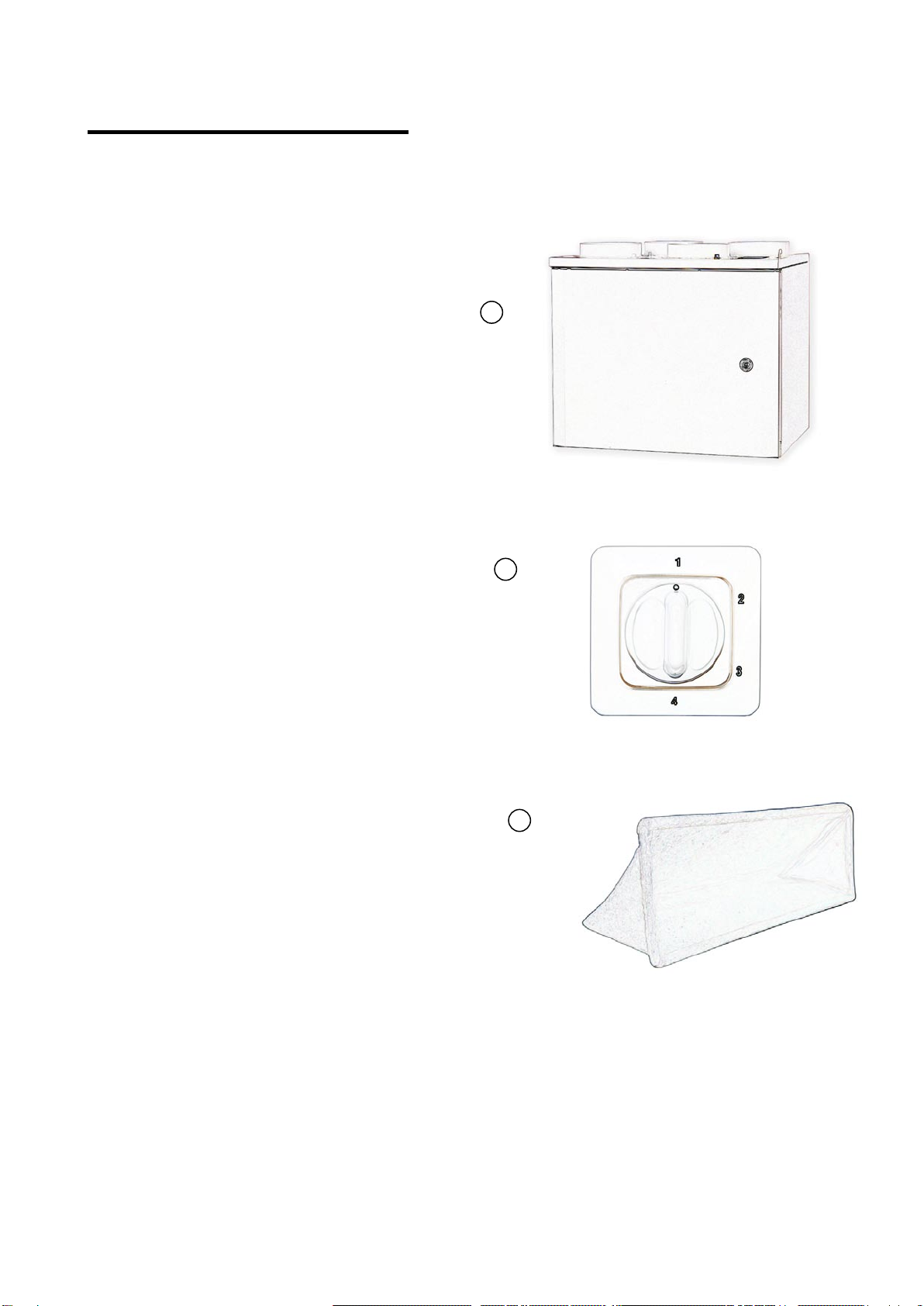
STAND ARD PARTS
1. Fenix ventilation unit
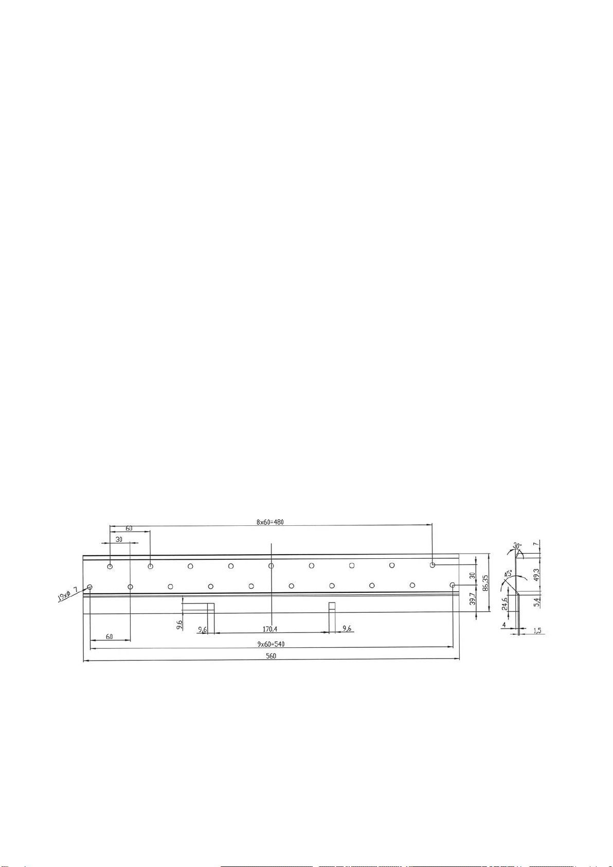
2. Wall mounting bracket
3. MCC control panel
EXTRA EQUIPMENT
4. Spare filter EU5
ADDITIONAL EQUIPMENT
5. Mounting plate for ceiling installation
6. Fine filter EU7 cassette
1
3
4
11
INSTALLATION
The unit should be installed on the wall or in the ceiling of a warm or half warm room (over
+5 °C). The location can be for example a scullery or utility room, however, not the garage
(a separate fire area). The unit must be drained. There is a drain outlet (1/4” inner thread)
in the bottom of the unit. At the time of delivery, the outlet is plugged.
Phases of installation (installation on the wall):
A1 Mark and cut the holes in the ceiling.
B1 Draw the ducts through the holes to the required height. The gaps between duct and
steam barrier are then sealed, with for instance ventilation tape.
C1 Fasten the wall bracket with screws to the wall (picture C1). Install an insulation
board between the wall and the unit to reduce the transfer of machine noise or
vibration. The insulation also keeps the unit in a vertical position.
D1 Lift the unit onto the bracket and fasten to the wall with two screws from inside the
unit (pictures D1).
E1 Connect the ducts to the tubes on top of the unit. It is recommended that silencers be
installed to the exhaust air and supply air ducts. Silencers, see page 7.
F1 Drain the unit. Connect a pipe between the drain outlet (¼” inside thread) and the
nearest floor drain or water trap of a sink. Connecting the unit directly into the
sewage system is not allowed. The drainage must always be done through a water
trap, otherwise the condense water will not be removed when the fans are on.
Picture C1. The wall bracket

12
Pictures D1. Securing the fastening with two screws

13
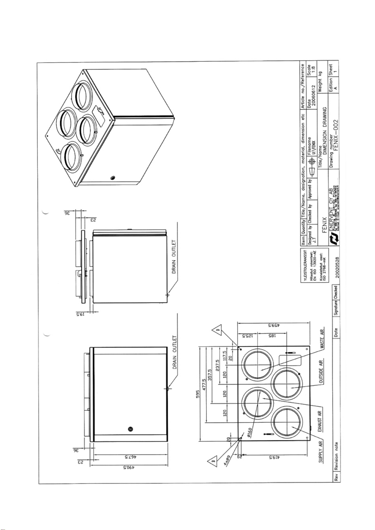
Fenix dimension drawing (wall mounting), left handed

14
Phases of installation (installation in the ceiling):
A. Cut the holes and install supporting rails in the ceiling. Fasten the mounting plate
firmly. The steam barrier remains between the mounting plate and the supporting rails.
B. Draw the ducts to the attic and connect them to the mounting plate.
C. Lift the unit up to the mounting plate and fasten it with four machine bolts.
D. It is recommended that silencers be installed to the exhaust air and supply air ducts.
Silencers, see page 7.
E. Drain the unit. Connect a pipe between the drain outlet (¼” inside thread) and the
nearest floor drain or water trap of a sink. Connecting the unit directly into the sewage
system is not allowed. The drainage must always be done through a water trap,
otherwise the condense water will not be removed when the fans are on.
15
Fenix dimension drawing (ceiling mounting), left handed

16
CHANGING THE HANDEDNESS
The unit is delivered left handed from the factory. The handedness can easily be changed.
The ceiling mounting plate is the same regardless of the handedness.
1. Moving the electrical heating coil:
The electrical heating coil must always be between the heat recovery and supply air fan.
- Detach the heating coil cabel. It is connected with a bayonet socket.
- Unscrew the two fixing screws (crosshead).
- Fasten the heating coil with screws to the supply air fan fixing plate.
- Attach the heating coil cabel.
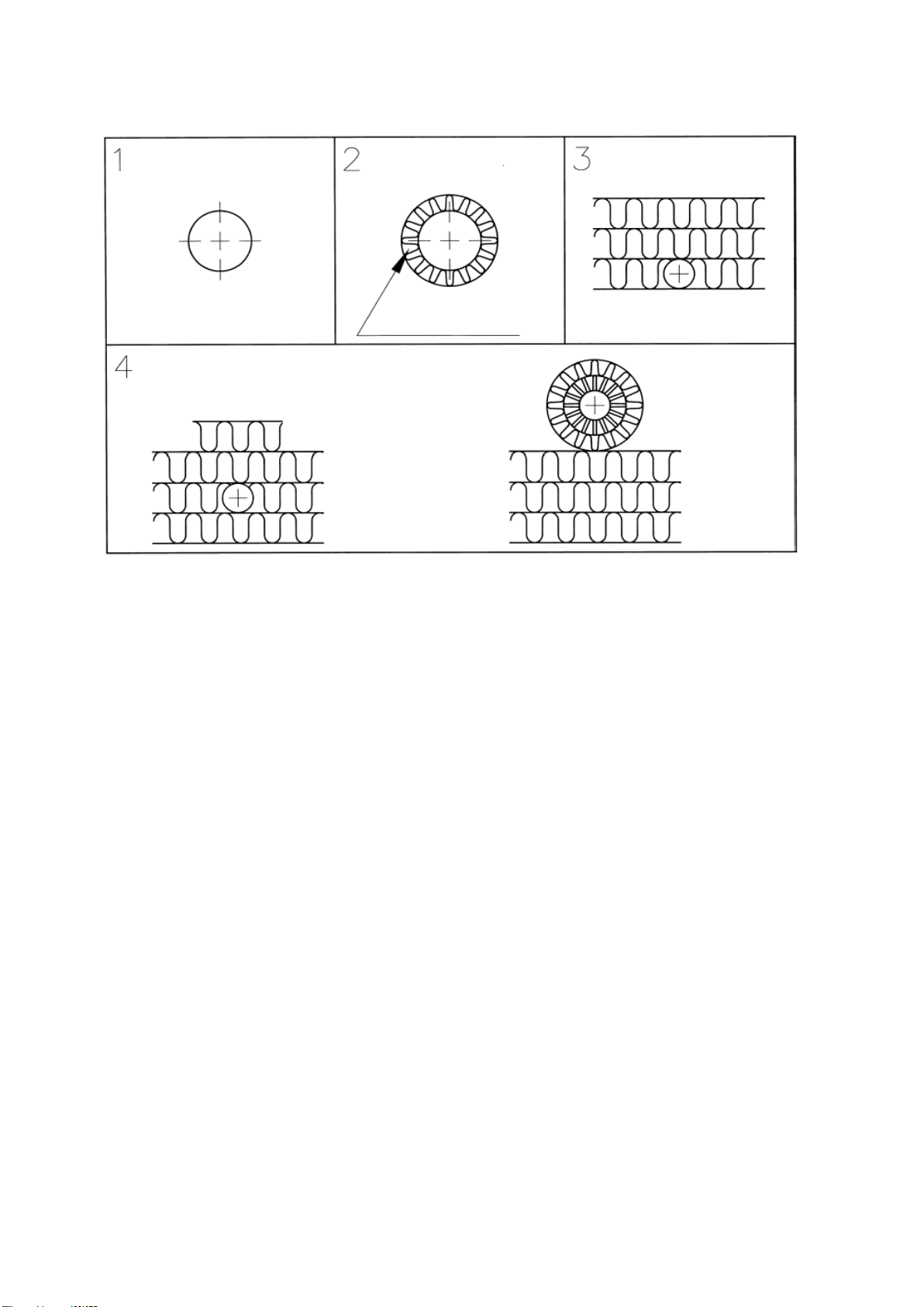
2. Turning the heat exchanger:
In the back of the heat exchanger is a fixed by-pass channel that always must be on the
outside air / supply air side.
The by-pass channel is opened by turning the by-pass damper preventing the outside air
from flowing through the heat exchanger.
The by-pass channel is shut with the by-pass damper allowing the outside air to flow
through the heat exchanger.
- Remove the by-pass damper from the outside air surface of the heat exchanger.
- Pull the heat exchanger out of the unit.
- Turn the heat exchanger 90° (1/4 lap) and push it back into the unit.
- Put the by-pass damper back in its new place.

17
3. Moving the fine filter:
If the unit is equipped with a F7 fine filter cassette, it needs to be moved to the outside air
side when the handedness is changed.
4. The duct connection markings:
Fasten new stickers to the duct connections so that the outside air and exhaust air / supply
air and waste air change places.
OUTSIDE AIR ↔ EXHAUST AIR
SUPPLY AIR ↔ WASTE AIR
18
HEAT INSULATION OF THE DUCT SYSTEM
Insulation
2 x 100mm
Insulator 20mm
Closed cell type
The figure shows different examples of ductwork insulation.
1. Exhaust air duct in warm state (indoor, no insulation).
2. Waste air duct and fresh air duct in warm state (indoor).
Insulation, for example Armaflex™
3. Exhaust air duct on attic under the insulation but above the steam barrier.
4. All air ducts on a cold attic. The waste or fresh air ducts must not be installed
immediately above the steam barrier; there should be a mineral wool insulating layer of
at least 100 mm between them.
19
OPERATION
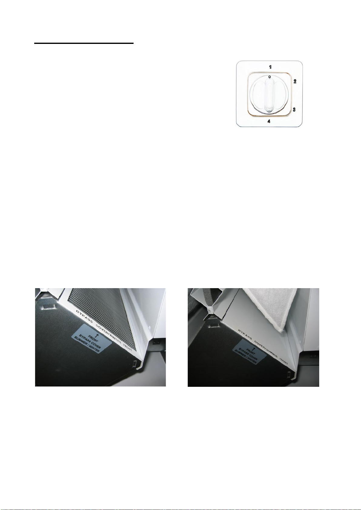
Fan speed
Always keep the Fenix ventilation unit on and running.
Fan speed (efficiency) is regulated with the knob on
the control panel. There are four speeds available.
After heating
The supply air is heated after the heat exchanger with
an electrical heating coil to the temperature set on the
thermostat. The heating coil is equipped with an
automatic over heating protector and a manually set
off temperature limiter.
Freeze protection of the heat exchanger
Freezing of the heat exchanger is prevented by limiting the waste air temperature to
+2…+5°C. When the waste air temperature drops to +2°C the supply air fan stops, and the
waste air temperature starts rising. When the temperature reaches +5°C the supply air fan
starts again.
By-pass damper
The summer by-pass is used when heat recovery from the exhaust air is not needed
(when the outside temperature is over +12…15°C).
The winter damper is used when heat recovery from the exhaust air is wanted (when the
outside temperature is below +12°C).
Winter damper in use (left handed Fenix) Summer by-pass in use (left handed
Fenix)
MCC control panel

20
MAINTENANCE
Fenix does not require any mechanical maintenance, only changing of the filters
periodically and cleaning of the heat exchanger and fans (when needed). The power
supply to the unit is cut when the service hatch is opened.
The unit has one hinged door in the front
The door can be lifted off the hinges.
Cleaning the heat exchanger. When changing the filters, check the condition of the heat
exchanger. If cleaning is required, remove it from the unit and carefully wash through the
air channels with a hand shower using a neutral detergent. The heat exchanger can also
be cleaned by blowing through the air channels using compressed air. Do not use a
pressure washer and do not submerge the heat exchanger into water!!
Cleaning the fans. When changing filters, also check the condition of the fans. If cleaning
is needed the fans are removed from the device and cleaned with a toothbrush or
compressed air.
Changing of filters. The recommended time between F5 filter changes is max six (6)
months. The F5 filter can be cleaned between changes by vacuuming, which makes it
possible to keep the same filters for up to one year. The F7 filter should be changed every
12 months. Draw the filters from the device and replace with new filters. The F7 filter is
installed on the outside air side. Vacuum cleaning the inside of the device is recommended
at this point. Close the door carefully.
Regulating the proportion of supply air and exhaust air. The exhaust air flow should
be 5 - 10 % greater than the supply air flow. This is performed by accurately measuring the
air flow through all of the valves with for example a thermo anemometer and by adjusting
them to the correctly calculated values. A correctly balanced system returns a good heat
recovery rate and keeps a slight negative pressure in the building. The negative pressure
keeps the humidity away from the structures. When an adjustment is made, the filters must
be clean and all the valves and outer grilles must be in place. There must not be an insect
net over the fresh air grille.
This manual suits for next models
3
Table of contents
Other enervent Ventilation Hood manuals


Popular Ventilation Hood manuals by other brands

Helios
Helios BK Series Installation and operating instructions

Savo
Savo I-7804-S Instruction manua

Victory
Victory Twister MAX Installation guide and user's manual

Westinghouse
Westinghouse WRR626 B user manual

Think Appliances
Think Appliances GEH9010G user manual

Yale
Yale PWLCL636SS Installation instruction guide


