ENFORCER
ENFORCERENFORCER
ENFORCER
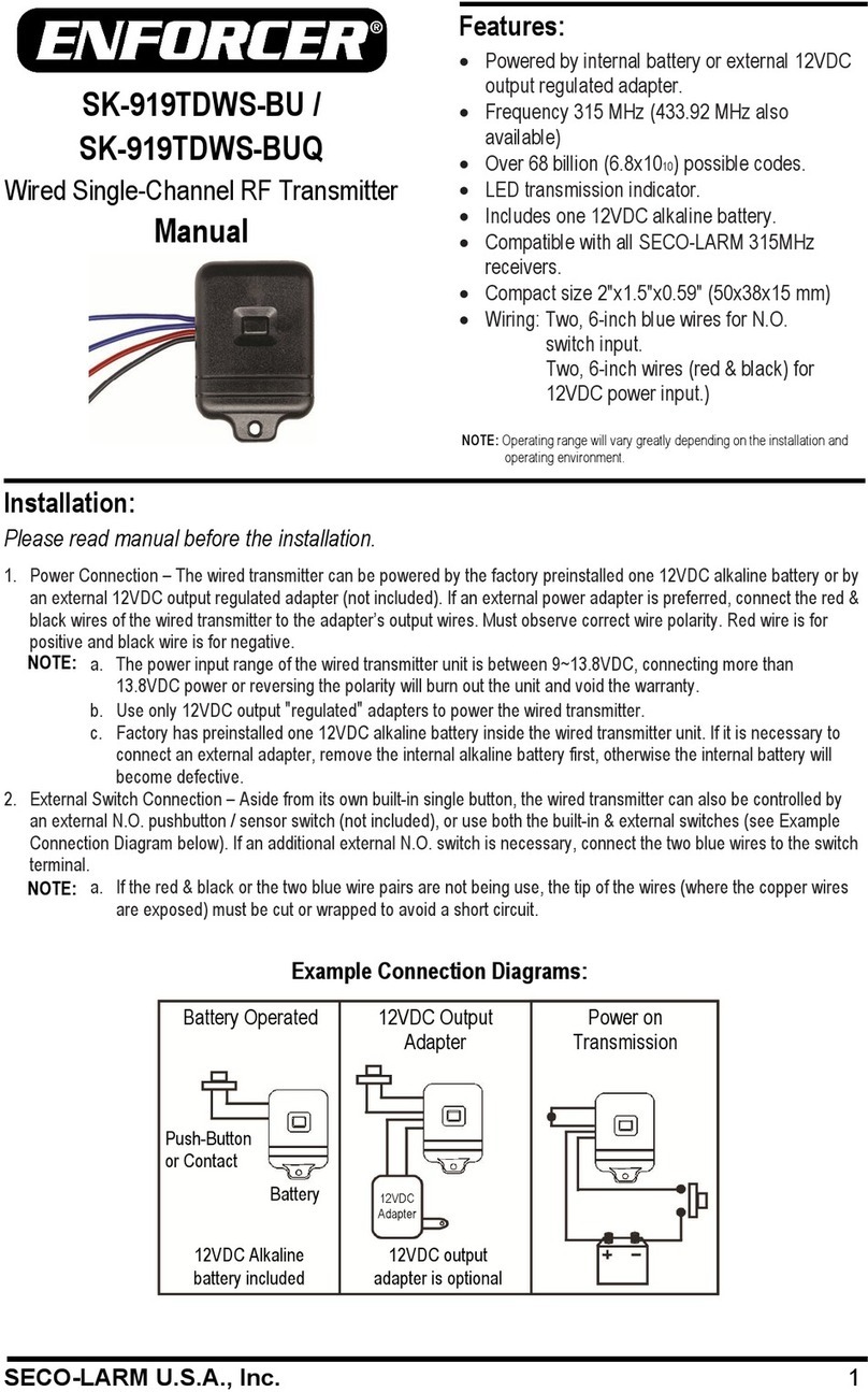
Wired Single-Channel RF Transmitter
Installation
Power Connection
The wired transmitter can be powered by the factory preinstalled 3V C lithium battery (CR-2032) or by
an external 3~13V C output regulated adapter (not included).
If an external power adapter is preferred, connect the red and black wires of the wired transmitter to the
adapter's output wires, being careful to ensure correct polarity. The red wire is connected to the positive
and the black wire to the negative.
NOTES:
•The power input range of the wired transmitter is 3~13V C and is polarity sensitive. Connecting
more than 13V C or reversing the polarity will burn out the unit and void the warranty.
•Use only "regulated" adapters to power the wired transmitter.
•If using an external power adapter, the factory-installed lithium CR-2032 battery will serve as a
backup in case of power interruption (Battery must be removed for external inline power-on switch).
•If connected to an external power-on switch, it is suggested that you remove the battery to disable
the built-in button so that it can only be controlled by the power-on switch.
External Switch Connection
The wired transmitter can be controlled by its built-in button (see Fig. 1), by an external N.O. switch* only
(button, contact, or sensor, see Fig. 2), or by both (Fig. 3). To disable the built-in button, the external
switch must be installed inline to the positive terminal of the power source with the battery removed.
NOTES:
•Any wires not in use must be insulated to avoid a short-circuit
•o not let the red wire touch any other wire. oing so may burn out the transmitter.
*
Switch not included
SECO-LARM® U.S.A., Inc.
16842 Millikan Avenue, Irvine, CA 92606
WA ANTY: This SECO-LARM product is warranted against defects in material and workmanship while used in normal service for one (1) year from the date of sale
customer. SECO-LARM’s obligation is limited to the repair or replacement of any defective part if the unit is returned, transportation prepaid, to SECO-LARM. This Warranty
if damage is caused by or attributed to acts of God, physical or electrical misuse or abuse, neglect, repair or alteration, i
mproper or abnormal usage, or faulty installation, or if for any
other reason SECO-LARM determines that such equipment is n
ot operating properly as a result of causes other than defects in material and workmanship. The sole obligation of
SECO-LARM and the purchaser’s exclusive remedy, shall be limited to the replacement or repair only, at SECO-LARM’s option. In no event shall SECO-
special, collateral, incidental, or consequential personal or property damage of any kind to the purchaser or anyone else.
NOTICE: The SECO-LARM policy is one of continual development and improvement. For that reason, SECO-LA
RM reserves the right to change specifications without notice.
SECO-LARM is also not responsible for misprints. All trademarks are the property of SECO-LARM U.S.A., Inc. or their respective owners. Copyright © 2021 SECO-LARM U.S.A.,
All rights reserved.
California Proposition 65 Warning:
These products may contain chemicals which are known to the State of California
to cause cancer and birth defects or other reproductive harm.
For more information, go to www.P65Warnings.ca.gov.
+
–
Red
Black
†
†
‡AC Adapter optional
Adapter‡
External switch and
built-in button
+
–
Red
Black
Blue wires
†
insulate red and black wires.
Adapter†
power-on switch
+
–
Red
Black
Blue wires†
†
must be removed in this situation.
Adapter
FCC COMPLIANCE STATEMENT (SK-919T1-GBWQ) FCC ID: K4E919T2GDW
This device complies with part 15 of the FCC rules. operation is subject to the following two conditions: (1) this device may not cause harmful interference and (2)
accept any interference received, including interference that may cause undesired operation.
Notice: The changes or modifications not expressly approved by the party responsible for compliance could void the user’s authority to operate the equipment.
IMPORTANT NOTE: To comply with the FCC RF exposure compliance requirements, no change to the antenna or the device is permitt
ed. Any change to the antenna or the device
could result in the device exceeding the RF exposure requirements and void user’s authority to operate the device.


