EngA AF Series User manual

IOM-52 Apr 13 R2
INSTALLATION, OPERATION
AND MAINTENANCE MANUAL
FOR
AF / DCU SERIES
AIR COOLED CONDENSERS and FLUID COOLERS
UNIT MODEL NO. _________________
UNIT SERIAL NO. _________________
SERVICED BY: ___________________
TEL. NO: ________________________
CANADIAN
HEAD OFFICE
AND FACTORY
USA
HEAD OFFICE
AND FACTORY
CANADIAN
EASTERN FACTORY
1401 HASTINGS CRES. SE
CALGARY, ALBERTA
T2G 4C8
Ph: (403) 287-4774
Fx: 888-364-2727
32050 W. 83rd STREET
DESOTO, KANSAS
66018
Ph: (913) 583-3181
Fx: (913) 583-1406
1175 TWINNEY DRIVE
NEWMARKET, ONTARIO
L3Y 5V7
Ph: (905) 898-1114
Fx: (905) 898-7244
SALES OFFICES ACROSS CANADA AND USA
Retain instructions with unit and maintain in a legible condition.
Please give model number and serial number when contacting
factory for information and/or parts.
www.engineeredair.com

AAF / DCU MANUAL
IOM-52 2 of 23 Apr 13 R2
TABLEOFCONTENTS
Safetyprecautions.............................................................................................................................................................................3
Youhaveresponsibilitiestoo.............................................................................................................................................................3
Introduction.......................................................................................................................................................................................3
Warranty............................................................................................................................................................................................4
Parts...................................................................................................................................................................................................5
Receiving............................................................................................................................................................................................5
Temporarystorage.............................................................................................................................................................................5
Installation..........................................................................................................................................................................................6
Codes..................................................................................................................................................................................................6
Clearanceforairflow.........................................................................................................................................................................7
Qualifiedinstaller...............................................................................................................................................................................7
Refrigerationpipingrecommendations.............................................................................................................................................7
Undergroundrefrigerantpiping...............................................................................................................................................7
Pipingconnectionsizes.............................................................................................................................................................8
Traps.........................................................................................................................................................................................8
Liquidline.................................................................................................................................................................................8
Dischargeline...........................................................................................................................................................................8
Refrigerationspecialties(byothers).........................................................................................................................................9
Servicevalves(recommended).................................................................................................................................................9
Sightglass/moistureindicator(required).................................................................................................................................9
Liquidlinefilter‐drier(required)...............................................................................................................................................9
Liquidlinesolenoidvalve(required)......................................................................................................................................10
Thermostaticexpansionvalve(required)...............................................................................................................................10
Dischargecheckvalves...........................................................................................................................................................10
Refrigerationtable1equivalentlength..................................................................................................................................10
Refrigerationtable2(R410A)pipingguidelinesfornormalairconditioningduty................................................................11
Refrigerationtable2(R407C)pipingguidelinesfornormalairconditioningduty.................................................................12
Refrigerationtable2(R134a)pipingguidelinesfornormalairconditioningduty.................................................................13
Refrigerationtable3...............................................................................................................................................................14
Refrigerationtable4...............................................................................................................................................................14
Refrigerationpipingmaterialsandprocedures...............................................................................................................................15
Tubing.....................................................................................................................................................................................15
Leakchecking..........................................................................................................................................................................16
Evacuationanddehydration...................................................................................................................................................16
Refrigerantcharging.........................................................................................................................................................................17
Flushinganddegreasingofwaterandglycolcoils...........................................................................................................................18
Heattransferfluids.................................................................................................................................................................18
Shutdownprocedure.......................................................................................................................................................................18
Maintenance....................................................................................................................................................................................19
Heresite®maintenance.....................................................................................................................................................................19
Electrical...........................................................................................................................................................................................20
Beltadjustment................................................................................................................................................................................20
Setscrews.........................................................................................................................................................................................20
Motorlubrication.............................................................................................................................................................................21
Dampers...........................................................................................................................................................................................21
Controls............................................................................................................................................................................................21
Refrigeration....................................................................................................................................................................................22
Seasonalmaintenance............................................................................................................................................................22
Condenserfancontroltypicalsettings.......................................................................................Error!Bookmarknotdefined.
Troubleshootingchart.....................................................................................................................................................................22
©AirtexManufacturingPartnership.Allrightsreserved.
AAF / DCU MANUAL
IOM-52 3 of 23 Apr 13 R2
SAFETYPRECAUTIONS
Read,understandandfollowthecompletemanualbeforebeginningtheinstallation,includingallsafety
precautionsandwarnings.
Warning:
Improperinstallation,adjustment,alteration,serviceormaintenancecancause
propertydamage,injuryordeath.Readtheinstallation,operatingandmaintenance
instructionsthoroughlybeforeinstallingorservicingthisequipment.
Warning:Thisunitisconnectedtohighvoltages.Electricalshockordeathcouldoccurif
instructionsarenotfollowed.Thisequipmentcontainsmovingpartsthatcanstart
unexpectedly.Injuryordeathcouldoccurifinstructionsarenotfollowed.Allwork
shouldbeperformedbyaqualifiedtechnician.Alwaysdisconnectandlockoutpower
beforeservicing.DONOTbypassanyinterlockorsafetyswitchesunderany
circumstances.
YOUHAVERESPONSIBILITIESTOO
Thisinstallation,operationandmaintenancemanualcannotcovereverypossibility,situationor
eventuality.Regularservice,cleaningandmaintainingtheequipmentisnecessary.Ifyouarenotcapable
ofperformingthesetasks,hireaqualifiedservicespecialist.Failuretoperformthesedutiescancause
propertydamageand/orharmtothebuildingoccupantsandwillvoidthemanufacturers’warranty.
INTRODUCTION
EngineeredAirunitsarehighqualityproductsdesignedandmanufacturedtoprovidemanyyearsof
trouble‐freeoperation.Werecommendthatthismanualbereadthoroughlytoensureproperinstallation,
efficientoperationandpropermaintenanceofthisequipment.Thesubmittalrecordisconsideredtobe
partoftheInstallation,OperationandMaintenanceManual.Pleasereportanyomissionstothenational
servicemanager.

AAF / DCU MANUAL
IOM-52 4 of 23 Apr 13 R2
WARRANTY
LIMITEDWARRANTYENGINEEREDAIRwillfurnishwithoutcharge,F.O.B.factory,freightcollect,
replacementpartsfor,orrepairstoproductscoveredhereinwhichprovedefectiveinmaterialor
workmanshipundernormalandproperuseforaperiodoftwelve(12)monthsfromtheinitialstart‐upor
eighteen(18)monthsfromthedateofshipment,whicheverexpiressooner,providedthecustomergives
ENGINEEREDAIRwrittennoticeofsuchdefectswithinsuchtimeperiodsandprovidedthatinspectionby
ENGINEEREDAIRestablishesthevalidityoftheclaimandallpertinentinvoiceshavebeenpaidinfull.The
repairsorreplacementswillbemadeonlywhenthecompleteproduct(s)orpart(s)claimedtobedefective
arereturnedtoENGINEEREDAIRoradepotdesignatedbyENGINEEREDAIR,transportationcharges
prepaid.Repairsorreplacementsasprovidedforbythisparagraphshallconstitutefulfillmentofall
ENGINEEREDAIR'sobligationswithrespecttothiswarranty.Therefrigerantchargeisnotincludedinany
partofthiswarranty.Thiswarrantydoesnotapplytoanyproductsorpartsthereofthathavebeensubject
toaccident,misuseorunauthorizedalterations,orwhereENGINEEREDAIR'sinstallationandservice
requirementshavenotbeenmet.
Theforegoingwarrantyisinlieuofallotherwarranties,expressorimplied.ENGINEEREDAIRspecifically
disclaimsanyimpliedwarrantyofmerchantabilityand/orfitnessforpurpose.Undernocircumstances
shallENGINEEREDAIRbeliableto,norberequiredtoindemnify,Buyeroranythirdpartiesforanyclaims,
losses,labor,expensesordamages(includingspecial,indirect,incidental,orconsequentialdamages)of
anykind,resultingfromtheperformance(orlackthereof)ofthisAgreementortheuseof,orinabilityto
usethegoodssoldhereunder,including,butnotlimitedto,damagesfordelay,temporaryheating/cooling
costs,lossofgoodwill,lossofprofitsorlossofuse.Furthermore,thepartiesagreethattheBuyer'ssole
remedyunderthisagreementshallbelimitedtothelimitedwarrantysetforthintheprecedingparagraph
relatingtotherepairorreplacementofanydefectivegoods.Undernocircumstancesshallanyclaimor
awardagainstENGINEEREDAIRexceedtheoriginalcontractpricewhetherawardedthrougharbitration,
litigationorotherwise.
ENGINEEREDAIRWarrantyisvoidif:
1. Theunitisnotinstalledinaccordancewiththismanual.
2. Thestart‐upandoperationoftheunitisnotperformedinaccordancewiththismanual.
3. Theunitisoperatedinanatmospherecontainingcorrosivesubstances.
4. Theunitisallowedtooperateduringbuildingconstruction.

AAF / DCU MANUAL
IOM-52 5 of 23 Apr 13 R2
PARTS
Warning:
Anyreplacementpartmustbeofequivalentlistingorcertificationandbefunctionally
equivalent.Thereplacementpartmustmeettheoriginal’sspecificationintermsof
functionalityincludingcertifications,timing,inputandoutputrange,accuracyand
operation.
Failuretoreplacepartsorcomponentswithequivalentpartscancauseproperty
damage,injuryordeath.
1. Motors:
Motormanufacturershaveservicecentersthatwillrepairorreplacemotorsasrequired.
2. PartsOtherThanMotors:
ContactthenearestEngineeredAirsalesofficeorfactory.BesuretoincludeModelNumber,Serial
Number,dateofinstallationandnatureoffailurealongwiththedescriptionofthepartsrequired.
Somepartsmaynotbestockeditemsthatmustbemadeorordered.
RECEIVING
Refertothebackofthepackingslipforreceivingunitinstructions.
Onreceiptoftheunit,checkfordamage.Inspectprotectivecoversforpuncturesorothersignsthatthere
maybeinternaldamage.Removeprotectivecoversandcheckforinternaldamage.Replacecoversifthe
unitisnotbeingassembledorinstalledatthistime.Openaccessdoorsandcheckforinternaldamage.
Closeaccessdoorswhentheinspectioniscomplete.Ifdamageisfoundfollowtheinstructionsonthe
packingslip.
Onreceiptoftheunit,checkelectricalcharacteristics(seeratingplate)tomakesuretheunitvoltageis
compatiblewiththatavailablefortheunit.Allpartsforfieldinstallationarelistedontheshippingorder
form.
TEMPORARYSTORAGE
Ifaunitistobestoredpriortoinstallationthefollowingprecautionsarerequired:
• Storeinawelldrainedareathatwillnotaccumulatesurfacewater.
• Storeinanareawheretheunitwillnotgetdamaged.
• Theentireperimeterandanyfullheightcrossmembersoftheunitmustbesupportedbyalevel
surfaceandthesupportingsurfacemustbeadequateforsupportingtheentireweightoftheunit.
• Allprotectivecoveringsthatwereprovidedforshippingmustbeinplace.

AAF / DCU MANUAL
IOM-52 6 of 23 Apr 13 R2
INSTALLATION
Warning: Thisunitisnotratedforhazardouslocationsandcannotbeinstalledinareasrequiring
anyhazardouslocationrating.
Caution: Allwiringandpipinginstallationmustbecompletedbyqualifiedpersonsin
accordancewithallfederal,state,provincialand/orlocalcodes.
Note: Installationshallbeinaccordancewiththismanualandallotherassociated
componentandcontrolInstallation,OperationandMaintenanceManuals.
CODES
InCanada:
1. TheinstallationofthisunitshallbeinaccordancewiththelatesteditionoftheCanadianElectrical
Code,Part1–C.S.A.StandardC22.1,ProvincialandLocalCodes,andinaccordancewiththelocal
authoritieshavingjurisdiction.
2. ThisunitshallbeelectricallygroundedinaccordancewiththelatesteditionoftheCanadianElectrical
Code,Part1–C.S.A.StandardC22.1,ProvincialandLocalCodes,andinaccordancewiththelocal
authoritieshavingjurisdiction.
3. TheinstallationofthisunitshallbeinaccordancewiththelatesteditionoftheCanadianNaturalGas
andPropaneInstallationCode,C.S.A.StandardB149.1,ProvincialandLocalCodes,andinaccordance
withthelocalauthoritieshavingjurisdiction.
4. TheinstallationofthisunitshallbeinaccordancewiththelatesteditionoftheNationalPlumbingCode
ofCanada,ProvincialandLocalCodes,andinaccordancewiththelocalauthoritieshavingjurisdiction.
5. TheinstallationofthisunitshallbeinaccordancewithallotherNational,ProvincialandLocalCodes,
andinaccordancewiththelocalauthoritieshavingjurisdiction.
InUSA:
1. TheinstallationofthisunitshallbeinaccordancewiththelatesteditionoftheNationalElectrical
Code(ANSI/NFPA70),StateandLocalCodesandinaccordancewiththelocalauthoritieshaving
jurisdiction.
2. ThisunitshallbeelectricallygroundedinaccordancewiththelatesteditionoftheNational
ElectricalCode(ANSI/NFPA70),StateandLocalCodesandinaccordancewiththelocalauthorities
havingjurisdiction.
3. Iftheunithasnotbeenprovidedwithanelectricdisconnectswitch,oneofadequateampacity
shallbeinstalledinaccordancewithArticle430oftheNationalElectricalCode(ANSI/NFPA70).
4. TheinstallationofthisunitshallbeinaccordancewiththelatesteditionoftheNationalFuelGas

AAF / DCU MANUAL
IOM-52 7 of 23 Apr 13 R2
CodeANSI/Z223.1/NFPA54,StateandLocalCodesandinaccordancewiththelocalauthorities
havingjurisdiction.
5. TheinstallationofthisunitshallbeinaccordancewiththelatesteditionoftheNationalStandard
PlumbingCode(NSPC),StateandLocalCodesandinaccordancewiththelocalauthoritieshaving
jurisdiction.
6. TheinstallationofthisunitshallbeinaccordancewithallotherNational,StateandLocalCodes,
andinaccordancewiththelocalauthoritieshavingjurisdiction.
CLEARANCEFORAIRFLOW
Properairflowisessentialfortheoperationofthisequipment.Maintainatleast60”(1500mm)clearance
betweenthecoilandanyobstruction.Maintainatleast96”(2400mm)betweenadjacentsections.Donot
placeinawell.Wellscreateasituationwhereairre‐circulatesfromthefanbacktothecoil.Enclosures
mustbedesignedforproperairflowandtopreventblockageorre‐circulatedair.
QUALIFIEDINSTALLER
Tocompletetheinstallation,arefrigerationcontractorexperiencedandqualifiedinsystempipingis
required.Thecontractorisresponsibleforthedesign,selectionandinstallationoftherefrigeration
specialtiesandrefrigerantpipingforthisequipment.Thefollowinginformationisintendedtoprovide
generalinformationandguidelinesforthesuccessfulinstallationofthisequipment.
FordetailedinformationaboutinstallationpracticesconsultASHRAEhandbooks,ANSI/ASMECodes,
ANSI/ASHRAESafetyCodeforMechanicalRefrigeration,CAN/CSAB52MechanicalRefrigerationCodeand
anylocalauthoritieshavingjurisdiction.
Note:
Componentselection,pipingdesignandinstallationoftheairconditioningsystemarethe
responsibilityoftheinstallingcontractor.Thismanualisdesignedtoprovidegeneral
guidelinesandrecommendationsonly.Itisnotintendedtobeacompletemanualforair
conditioningdesign.
REFRIGERATIONPIPINGRECOMMENDATIONS
UNDERGROUNDREFRIGERANTPIPING
Caution:
Undergroundcondenserrefrigerantpipingisnotrecommended.
Improperinstallationofacondensingunitwithundergroundpipingwillresultin
equipmentfailure.
ConsultFactoryonallsystemswithundergroundrefrigerantpiping.
Undergroundpipingwillvoidcompressorwarrantyunlessspecificallyauthorizedby
EngineeredAir.
Intheoffcycle,therefrigerantchargewillmigratetothecoldestlocation.Typically,groundtemperatures
arecoolerthanairtemperatures,andtheundergroundpipingbecomesthecoolestlocation.Inthiscase
therefrigerantchargewillmigratetoundergroundpiping.Whenthecompressorstarts,anyliquid
refrigerantinthedischargelinecouldcausenuisancetrippingonhighheadpressure.

AAF / DCU MANUAL
IOM-52 8 of 23 Apr 13 R2
PIPINGCONNECTIONSIZES
Refrigerantpipingmustbeselectedtomeettheconditionsrequiredforyourspecificinstallation.The
tubingconnectionsizesontheequipmentmayormaynotbethecorrectsizeforyourspecificapplication.
Note:
DONOTselecttubingsizesbasedonthesizeoftheconnectionstubs.
Thecorrecttubingsizeforyourinstallationmustbecheckedandselectedforeachandevery
job.
TRAPS
Itisrecommendedthattrapsbeinstalledonallsuctionordischargegasrisers.
LIQUIDLINE
Selectthelinesizeusingpipingtables.
Liquidlinesshouldhaveamaximumrefrigerantvelocityof350feetperminute(1.78m/s)toavoidliquid
hammer.Selectpressuredropforatemperaturepenaltyoflessthan2°F(1°C).Ifaliquidlinetravels
throughawarmarea,suchasaboilerroom,insulatethelinetopreventheatgain.
Ensurethetemperaturepenaltydoesnotexceedthesubcoolingprovidedbythecondensingunit.
AsightglassshouldbeinstalledattheTXvalvetoensurethevalveisreceivingasolidcolumnofliquidif
adequatesubcoolingisaconcern.AnEngAIntercoolermaybeorderedandinstalledtohelpreducethe
effectsofinadequatesubcooling.
DISCHARGELINE
Dischargelinesmustbeselectedtobalancetworequirements;minimizepressuredropandensure
adequatelinevelocitytoallowforoilreturn.Horizontaldischargelinesshouldbeslopeddowninthe
directionofflow.Usesizingtablestoselecttubingsizesbasedoncapacity,equivalentlengthand
maximumsizeforoilreturn.
A
AF / DCU MANUAL
IOM-52 9 of 23 Apr 13 R2
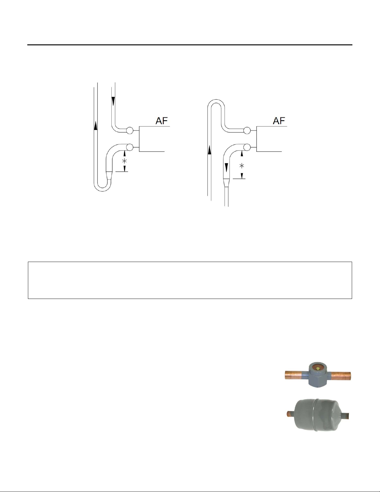
Thesketchbelowdescribesaboveandbelowpipingconnectionsandtraprequirements.Onlyinstall
reducersontheverticalline,atleast12”(300mm)belowtheheaderconnection.
*12”(300mm)minimumheightbeforereducingsize.
REFRIGERATIONSPECIALTIES(BYOTHERS)
Note:
Refrigerantspecialtiesareselected,suppliedandinstalledbytheinstallingcontractor.
Mostofthesedeviceshavespecifieddirectionsofflowandmaybepermanentlydamagedif
notinstalledcorrectly.Alwaysfollowtheinstallationinstructionsprovidedwiththe
components.
SERVICEVALVES(Recommended)
Servicevalvesshouldbeinstalledtoallowservicingoftheequipment.Aliquidlineservicevalveatthe
condensingunitisconsideredaminimumrequirement.
SIGHTGLASS/MOISTUREINDICATOR(Required)
Sightglassesareinstalledintheliquidlinetogiveavisualindicationofthe
refrigerantcharge.Themoistureindicatorgivesanindicationofthemoisture
contentoftherefrigerant.
LIQUIDLINEFILTER‐DRIER(Required)
Thefilter‐drierisinstalledintheliquidlinetofilterparticulateandforeignmatter
fromtherefrigerant.Filter‐driersalsoabsorbsmallamountsofmoistureandacid.
AAF / DCU MANUAL
IOM-52 10 of 23 Apr 13 R2
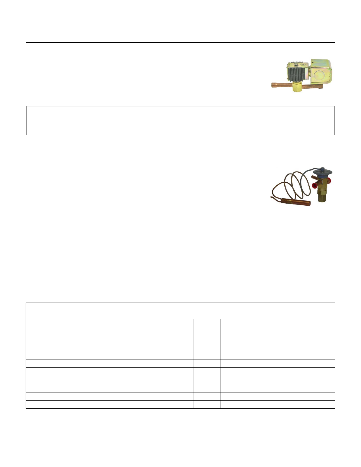
LIQUIDLINESOLENOIDVALVE(Required)
Theliquidlinesolenoidvalveisinstalledtocontrolliquidrefrigerantintheoff
cycle.ThesolenoidvalvemustbeinstalledclosetotheTXvalveattheevaporator
coil.Severaldifferentcontrolmethodsareusedtocontrolliquidlinesolenoid
valves.Seewiringdiagramandunitfunctionfordetails.
Note:
Liquidlinesolenoidvalvesmustbeinstalledattheevaporatorcoil,closetotheTXvalve.
THERMOSTATICEXPANSIONVALVE(Required)
Thethermostaticexpansionvalveissizedtomatchthecapacityofthesystem.The
TXvalveshouldbebalancedordualportedandmustbeexternallyequalized.One
valveisrequiredperdistributor.Theequalizationtubeconnectstothesuctionline
attheoutletoftheevaporatordownstreamofthebulb.TheTXvalvesensingbulb
isinstalledatthesamelocationtightlystrappedtothesuctionline.Suggested
positioningisatthesideofthepipe,atthe4:00o’clockor8:00o’clockposition.InsulatetheTXbulbafter
installation.
DISCHARGECHECKVALVES(Required)
Providedischargecheckvalve(s)totheinletoftheAF.Thiscontrolsliquidmigrationtothecompressorin
theoffcycle.
RefrigerationTable1EquivalentLength.
ACR(OD) Approximatepressurelossoffittings
(equivalentfeetoftubing)
Tubing
Size
90°
Std
90°
Long
Radius
90°
Street
45°
Std
Return
Bend
Tee
Branch
Flow
Tee
Straight
Through
Ball
Valve
Globe
Valve
Angle
Valve
1/2"OD 1.4 0.9 2.3 0.7 2.3 2.7 0.9 0.9 17 6
5/8”OD 1.6 1.0 2.5 0.8 2.5 3.0 1.0 1.0 18 7
7/8”OD 2.0 1.4 3.2 0.9 3.2 4.0 1.4 1.4 22 9
11/8”OD 2.6 1.7 4.1 1.3 4.1 5.0 1.7 1.7 29 12
13/8”OD 3.3 2.3 5.6 1.7 5.6 7.0 2.3 2.3 38 15
15/8”OD 4.0 2.6 6.3 2.1 6.3 8.0 2.6 2.6 43 18
21/8”OD 5.0 3.3 8.2 2.6 8.2 10.0 3.3 3.3 55 24
25/8”OD 6.0 4.1 10.0 3.2 10.0 12.0 4.1 4.1 69 29
AAF / DCU MANUAL
IOM-52 11 of 23 Apr 13 R2
RefrigerationTable2(R410A)PipingGuidelinesforNormalAirConditioningDuty.
R410A
Net
Evaporator
Capacity
EquivalentLength
(Actuallengthplusfittingsandvalves) Maximum
RiserSize
Tons Line 30feet 50feet 100feet 150feet
3tons Suction 3/4”(7/8”) 3/4”(7/8”) 7/8” 7/8” 7/8"
Discharge 1/2" 1/2" 5/8" 5/8" 5/8"
Liquid 3/8" 3/8” 1/2" 1/2"
Condensate 5/8" 5/8"
4tons Suction 3/4”(7/8”) 7/8" 7/8” 11/8” 7/8"
Discharge 1/2" 5/8" 5/8” 3/4”(7/8”) 5/8"
Liquid 3/8" 1/2” 1/2" 1/2"
Condensate 5/8" 5/8"
5tons Suction 7/8" 7/8" 11/8" 11/8" 11/8"
Discharge 5/8" 5/8” 3/4”(7/8”) 3/4”(7/8”) 5/8"
Liquid 1/2" 1/2" 1/2" 1/2”
Condensate 3/4”(7/8”) 3/4”(7/8”)
7.5tons Suction 7/8" 11/8" 11/8" 13/8" 13/8"
Discharge 5/8" 3/4”(7/8”) 7/8" 7/8" 3/4”(7/8”)
Liquid 1/2" 1/2" 1/2" 5/8"
Condensate 7/8” 7/8”
10tons Suction 11/8" 11/8" 13/8" 13/8" 13/8"
Discharge 3/4”(7/8”) 3/4”(7/8”) 7/8" 7/8" 7/8"
Liquid 5/8" 5/8" 5/8" 5/8”
Condensate 11/8” 11/8”
12.5tons Suction 11/8" 13/8" 13/8" 15/8" 15/8"
Discharge 7/8" 7/8" 7/8" 11/8" 7/8"
Liquid 5/8” 5/8" 5/8” 5/8”
Condensate 11/8" 11/8"
15tons Suction 13/8" 13/8" 15/8" 15/8" 15/8"
Discharge 7/8" 7/8" 11/8" 11/8" 11/8"
Liquid 3/4”(7/8”) 3/4”(7/8”) 3/4”(7/8”) 7/8"
Condensate 13/8" 13/8"
20tons Suction 13/8" 13/8" 15/8" 21/8" 15/8"
Discharge 7/8" 11/8" 11/8" 11/8" 11/8"
Liquid 7/8” 7/8” 7/8” 7/8”
Condensate 13/8” 13/8”

AAF / DCU MANUAL
IOM-52 12 of 23 Apr 13 R2
RefrigerationTable2(R407C)PipingGuidelinesforNormalAirConditioningDuty.
R407C
Net
Evaporator
Capacity
EquivalentLength
(Actuallengthplusfittingsandvalves) Maximum
RiserSize
Tons Line 30feet 50feet 100feet 150feet
3tons Suction 3/4”(7/8”) 7/8" 11/8” 11/8” 11/8"
Discharge
1/2" 5/8" 5/8" 3/4" 7/8"
Liquid 3/8" 3/8” 1/2" 1/2"
Condensate 5/8" 5/8"
4tons Suction 7/8" 7/8" 11/8” 11/8” 13/8"
Discharge
5/8" 5/8" 3/4”(7/8”) 7/8" 11/8"
Liquid 1/2” 1/2” 1/2" 1/2"
Condensate 5/8" 5/8"
5tons Suction 7/8" 11/8" 11/8" 13/8" 13/8"
Discharge
5/8" 3/4”(7/8”) 7/8" 7/8" 11/8"
Liquid 1/2" 1/2" 1/2" 5/8”
Condensate 3/4”(7/8”) 3/4”(7/8”)
7.5tons Suction 11/8" 11/8" 13/8" 13/8" 15/8"
Discharge
3/4”(7/8”) 7/8" 7/8" 11/8" 13/8"
Liquid 1/2" 5/8" 5/8" 5/8"
Condensate 7/8” 7/8”
10tons Suction 11/8" 13/8" 15/8" 15/8" 15/8"
Discharge
7/8" 7/8" 11/8" 11/8" 15/8"
Liquid 5/8" 5/8" 5/8" 3/4”(7/8”)
Condensate 11/8” 11/8”
12.5tons Suction 13/8" 13/8" 15/8" 21/8" 21/8"
Discharge
7/8" 7/8" 11/8" 11/8" 15/8"
Liquid 5/8” 5/8" 3/4”(7/8”) 3/4”(7/8”)
Condensate 11/8" 11/8"
15tons Suction 13/8" 15/8" 15/8" 21/8" 21/8"
Discharge
7/8" 11/8" 11/8" 13/8" 15/8"
Liquid 3/4”(7/8”) 3/4”(7/8”) 3/4”(7/8”) 7/8"
Condensate 11/8" 11/8"
20tons Suction 15/8" 15/8" 21/8" 21/8" 25/8"
Discharge
11/8" 11/8" 13/8" 13/8" 21/8"
Liquid 7/8" 7/8" 7/8" 11/8"
Condensate 13/8" 13/8"

AAF / DCU MANUAL
IOM-52 13 of 23 Apr 13 R2
RefrigerationTable2(R134a)PipingGuidelinesforNormalAirConditioningDuty.
R134a
Net
Evaporator
Capacity
EquivalentLength
(Actuallengthplusfittingsandvalves) Maximum
RiserSize
Tons Line 30feet 50feet 100feet 150feet
3tons
Suction 7/8” 11/8" 11/8” 13/8” 13/8"
Discharge 5/8" 3/4”(7/8”) 3/4”(7/8”) 7/8" 7/8"
Liquid 3/8" 3/8” 1/2" 1/2"
Condensate 5/8" 5/8"
4tons Suction 11/8” 11/8" 13/8” 13/8” 13/8"
Discharge 3/4”(7/8”) 3/4”(7/8”) 7/8” 7/8" 7/8"
Liquid 1/2" 1/2” 1/2" 1/2"
Condensate 7/8" 7/8"
5tons Suction 11/8" 13/8" 13/8" 15/8" 15/8"
Discharge 3/4”(7/8”) 7/8” 7/8" 11/8" 11/8"
Liquid 1/2" 1/2" 5/8" 5/8”
Condensate 7/8” 7/8”
7.5tons Suction 13/8" 13/8" 15/8" 15/8" 15/8"
Discharge 7/8" 7/8" 11/8" 11/8" 11/8"
Liquid 1/2" 1/2" 5/8" 7/8"
Condensate 7/8” 7/8”
10tons Suction 13/8" 15/8" 21/8" 25/8" 21/8"
Discharge 7/8” 11/8" 11/8" 11/8" 11/8"
Liquid 5/8" 5/8" 5/8" 3/4”(7/8”)
Condensate 11/8” 11/8”
12.5tons Suction 15/8" 15/8" 21/8" 21/8" 21/8"
Discharge 11/8" 11/8" 11/8" 13/8" 13/8"
Liquid 5/8” 5/8" 7/8” 3/4”(7/8”)
Condensate 11/8" 11/8"
15tons Suction 15/8" 21/8" 21/8" 21/8" 21/8"
Discharge 11/8" 11/8" 1 3/8" 13/8" 13/8"
Liquid 3/4”(7/8”) 3/4”(7/8”) 7/8” 7/8"
Condensate 13/8" 13/8"
20tons Suction 21/8" 21/8" 25/8" 25/8" 25/8"
Discharge 11/8" 13/8" 15/8" 15/8" 15/8"
Liquid 7/8” 7/8” 7/8” 7/8”
Condensate 13/8” 13/8”

AAF / DCU MANUAL
IOM-52 14 of 23 Apr 13 R2
NOTES:
1. SizesareODdimensions,TypeL,ACRrefrigerationtubing.
2. 3/4”(7/8”)notedabove:7/8”ACRtubingmayreplace3/4"asrequired.
3. Selectionsarebasedonequivalentlength.Equivalentlengthistheactuallengthplustheadditional
lossesinfeetduetofittings.SeeTable1forpressurelossesduetofittings.
(Ifnumberoffittingsisunknownanequivalentlengthestimatecanbemadebymultiplyingtheactual
pipingrunbyacomplexityfactorof1.5to2timestheactuallength.1.5timesforasimplesystemor
longrunsand2timesforaclosecoupledsystemoronewithalotoffittings.)
4. Forcompressorsorcircuitswithunloading(tandemcompressorsincluded).Alwayschecktubingsizes
foroilreturnattheunloadedconditions.Determinetheunloadedcapacityintonsandverifythatthe
selectedtubingisnotlargerthanmaximumrisersizeattheunloadedcapacity.
5. SelectionCriteriatodeveloptable.
Suctionline ‐ PDlessthan2°Ftemperaturepenalty.
Dischargeline‐ PDlessthan2.5°Ftemperaturepenalty.
Liquidline ‐ PDlessthan2°Ftemperaturepenalty,withvelocitylessthan350fpmtoavoidliquid
hammer.
Condensateline(condensertoreceiverifequipped‐velocitylessthan115fpm.(twophaseflow)with
notraps.
Maximumrisersizesarethelargestrecommendedtubingsizesforoilreturn.Sizesarebasedon75%
capacitytoallowforlowloadconditions.
Fordetailedevaluationofpipingsystems,guidelinesandpressurelossesconsultASHRAEhandbooks.
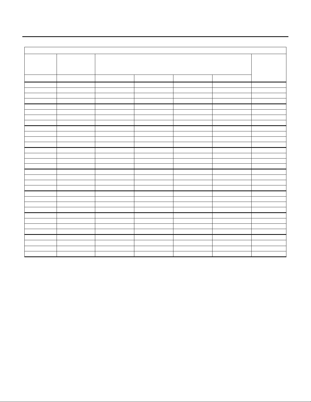
RefrigerationTable3
Approximateeffectofgaslinepressuredropon
compressorcapacityandpower(ASHRAE
REFRGERATION2.3)
LineLoss Capacity RequiredPower
Suction % %
0°F 100 100
2°F 96.4 104.8
4°F 92.9 108.1
Discharge % %
0°F 100 100
2°F 99.1 103.0
4°F 98.2 106.3
RefrigerationTable4
Weightofrefrigerantinliquidlinesper100ftoftubing(100°F)
Liquid
Line
R134a
Lbs(kg)
R407C
Lbs(kg)
R410A
Lbs(kg)
3/8” 3.9(1.8) 3.6(1.6) 3.4(1.5)
1/2” 7.3(3.3) 6.8(3.0) 6.2(2.8)
5/8” 12(5) 11(2.3) 10(4.5)
7/8” 24(11) 23(10.4) 21(9.5)
11/8” 41(19) 39(18) 36(16)
13/8” 63(29) 59(27) 54(24)

AAF / DCU MANUAL
IOM-52 15 of 23 Apr 13 R2
REFRIGERATIONPIPINGMATERIALSANDPROCEDURES
Note:
Aqualifiedrefrigerationcontractorexperiencedinrefrigerantpipingmustcompletethe
installation.Theinstallationmustbecompletedusingindustry‐acceptedmethodsand
materials.
WARNING:
TheAFunitisshippedwithaholdingchargeofdrynitrogen.
Thispressureshallbereleasedsafelybeforeopeningsystemorconnectingtubing.
TUBING
UseNitrogenizedACRgrade,‘TypeL’or‘TypeK’coppertubingonly.Allrefrigeranttubingshallbeclean
anddry.Thetubingshallbenitrogenpurgedduringthebrazingprocess.Thispreventsharmfulcopper
oxidesfromforminginthetubing.
WARNING:
Nitrogencylindersshallbeequippedwithahigh‐pressureregulatorandflowmeter.Do
notconnecthigh‐pressurecylinderstotherefrigerantcircuitwithoutaregulator.
Failuretodosomayresultinpropertydamage,injuryordeath.
Refrigeranttubingmustbecutwithatubecutterandtheendsdeburredbeforeinstallation.Neverusea
hacksaworabrasivecuttertocutrefrigerationtubing.
Longradiuselbowsshouldbeusedtoreducepressuredrop.
CoppertocopperconnectionsshouldbemadewithSILFOS,orsimilarsilverbearinglowtemperature
brazingmaterial.
Coppertobrassorcoppertosteeljointsshouldbemadewith45%silversolderandtheappropriateflux.
Fluxmustbecleanedfromtubingafterinstallation.
WARNING:
Softsolders(50/50,95/5,etc)arenotsuitableforusewithairconditioningsystems.
Allaccessoriesshallbeproperlyprotectedfromheatduringinstallation.Refertotheinstallationguidelines
suppliedwiththecomponents.Itispreferredtoinstallthefilter/drierlasttoavoidextendedexposureto
atmosphere(moisture).
Pipingshallbeproperlysupportedandallowancesshallbemadeforthermalexpansionorcontractionof
tubing.

AAF / DCU MANUAL
IOM-52 16 of 23 Apr 13 R2
LEAKCHECKING
Afterinstallation,alljoints,bothfactoryandfieldinstalled,shallbepressurecheckedandleaktestedusing
approvedindustrymethods.
WARNING:
Testpressuresmustnotexceedthemaximumpressureratingsspecifiedontheunit
ratingplate.
WARNING:
OxygenmustNEVERbeusedtopressurizeasystem.
Ensureallservicevalvesandmanualvalvesareopen.Ifleaksarelocated,removepressureandrepair
leaks.Recheckasnecessary.
Ifbrazingisnecessarytorepairleaks,adrynitrogenpurgethroughtubingwhilebrazingisrequiredto
preventtheformationofcopperoxides.
EVACUATIONANDDEHYDRATION
Thesystemmustbeevacuatedpriortocharging.Properevacuationwillremovenon‐condensablegasses
andwatervaporfromthesystem.Watervaporinthesystemwillcombinewiththeoilandrefrigerantto
formacidsandotherundesirableby‐products.Non‐condensablegassessuchasairornitrogenwill
increasetheheadpressureandoperatingtemperatureanddegradesystemperformance.
Sketchapipingschematicshowingallvalvesandcomponents.Checkthediagramtoensurethatall
portionsofthesystemwillbeevacuated.Addadditionalhosesorservicefittingsasrequired.
Note:
Ahighvacuumcannotbepulledthroughasolenoidvalvewhetherornotitisenergized.
Ahighvacuumcannotbepulledthroughacheckvalveregardlessofdirectionofflow.
EvacuationProcedure:
1. Removeleak‐testinggassesfromthesystem.Ifrefrigerantwasusedtoleaktest,therefrigerant
shallberecovered.
2. Connectahighvacuumpumptothesystem.Usetheshortestandlargestdiameterhoseavailable.
3. Useasmanyconnectionsasthesystemwillallow.
4. Ifevacuatingthrough‘Schraedervalves’,removetheSchraedervalvecorebeforeevacuation.
5. Openallservicevalves.
6. Useamicrongaugetomeasurethevacuum.
Note:
Astandardrefrigerationgaugewith“inchesofmercury”isnotsuitabletomeasurethehigh
vacuums.AhighvacuumgaugecapableofmeasuringMicronsisrequired.

AAF / DCU MANUAL
IOM-52 17 of 23 Apr 13 R2
7. Tripleevacuationorhighevacuationmethodsarebothacceptable.
8. Evacuatethesystemtoanultimatevacuumof500microns(0.5mmofmercury).
9. Checkunitrating‐plateforcorrectrefrigeranttype.Breakthevacuumwithvirginrefrigerantfroma
sealedcontainer.
10. Pressurizethesystemtoaslightpositivepressure,(oneortwopsig).ReplaceallSchraedervalve
cores.Donotallowairintothesystem.
11. Reinstallgauges,proceedtothestart‐upsectionforcharginginstructions.
CAUTION:
NEVERusesystemcompressorstoevacuateasystem.Operatingacompressorwhilethe
systemisunderahighvacuummaycauseinternalarcingofthewindingsand
compressorfailure.Compressordamagecausedbyhighvacuumoperationisnot
coveredbysystemwarranty.
REFRIGERANTCHARGING
Systemchargewilldependonthelengthandorientationoftheinstalledsystem.
AninitialestimateforanACsystemchargeis1lb.(0.5kg).pertonplustheweightofliquidintheliquid
line(seeTable4Weightofrefrigerantincopperlines).Ideallychargingshouldbedoneinwarmweather.
Iftheambienttemperatureislessthandesign,restricttheairflowacrossthecondensertoincreasehead
pressureto130°F(55°C)saturateddischargetemperatureforcharging.
1. Checkthatallmanualshutoffvalvesintherefrigerationcircuitareinthenormaloperating
position.
2. Weighinaninitialchargeofapproximately75%oftheestimatedcharge.
3. Checktoensureevaporatorsectionhasproperairflow.Checkstaticpressuredropandcompare
withdesignstatic.Checkinletairtemperaturetoevaporator.Ensurethatthereissufficientloadto
operatetheairconditioning.
4. Checkthesupplyvoltageandensurethatiswithin10%ofdesignvoltageonunitratingplate.
5. Checkcontrolvoltageatrefrigerantsolenoidvalvesandensurethatitiswithin10%ofrated
voltage.
6. Setcontrolstocallforcooling.
7. Closethesystemserviceswitch.
8. Withthesaturateddischargetemperatureapproximatelyequalto130°F(55°C),[475psig(R‐410a),
325psig(R‐407C)]Thisstepmayrequireblockingcondenserairflowtoincreaseheadpressure.
Chargesystemslowlyuntilthesightglassisclear.DONOTOVERCHARGE.
9. Checkevaporatorsuperheat.
AttachanaccuratetemperaturesensortightlytothesuctionlineattheTXbulb.Measurethe
suctionpressureatthecondensingunit.Add2psigtothispressureandconvertittothesaturated
suctiontemperatureusingtheappropriatepressuretemperaturetable.Subtractthesaturated
temperaturefromthetemperaturemeasuredattheTXbulb.Thisisthesuctionsuperheat.
Superheatshouldbebetween8°Fto14°F(5°to8°C)whenthesystemisoperatingatfullloadwith
aclearsight‐glass.
AAF / DCU MANUAL
IOM-52 18 of 23 Apr 13 R2
10. Setupthehotgasbypassvalve(optional).Usingapressure‐temperaturechartfindtherefrigerant
pressurethatcorrespondstoatemperatureof34°F(1°C).
Createalowloadconditionontheevaporatorbyrestrictingtheairflowacrosstheevaporator.
Adjustthehotgasbypassregulatorsothatitwillstarttoopenatthepressurecorrespondingto
34°F(1°C).IfthehotgassystemisequippedwithadesuperheatingTXvalve,measurethe
superheatatthecompressorandensurethevalveisworking.
11. CheckthesettingsoftheCondenserFanCyclingControls(CFC’s),adjustasrequired.
FLUSHINGANDDEGREASINGOFWATERANDGLYCOLCOILS
Coiltubingmaycontainmaterialorresiduefrommanufacturing,transportationorstorage.Toprevent
possibledamagetoothercomponentsinthesystem,thecoilsmustbeflushedanddegreased.Consulta
qualifiedwatertreatmentspecialist.
HEATTRANSFERFLUIDS
Thecoil(s)providedhavebeenselectedforusewithaspecificheattransferfluidasshownonthe
SubmittalRecord.Useofotherfluidswillresultindifferentperformanceandcandamagethecoil(s).
Itisimperativetoproperlyselectandapplyheattransferfluidsusedinheatingandcoolingsystems.
Untreated,improperlytreatedorimproperuseoffluidsoruseoffluidsnotapprovedforusein
commercialheatingandcoolingsystemscandamagecoilsandsystemcomponents.Forselectionand
applicationofheattransferfluids,alwaysfollowthemanufacturers’recommendationsincluding
treatment,mixingandfilling.Warrantywillbevoidifcoildamageresultsfrommisapplicationorimproper
treatmentoftheheattransferfluid.
SHUTDOWNPROCEDURE
Warning:
Electricalshockordeathcanoccurifinstructionsarenotfollowed.Thisequipment
containsmovingpartsthatcanstartunexpectedly.Injuryordeathcouldoccurif
instructionsarenotfollowed.Allworkshouldbeperformedbyaqualifiedtechnician.
Alwaysdisconnectpowerbeforeservicing.DONOTbypassanyinterlockorsafetyswitches
underanycircumstances.
1. Shutdown
Toshuttheunitdownforashorttime(suchasforinspectionorservice).Shutoftheserviceswitch
inthemaincontrolpanelthenturnoffthemaindisconnect.
2. Re‐StartafterShutdown
Turnonmaindisconnectfortheunit.Turnontheserviceswitchinthemainelectricalcontrol
panel.
AAF / DCU MANUAL
IOM-52 19 of 23 Apr 13 R2
MAINTENANCE
Warning: Thisunitisconnectedtohighvoltages.Electricalshockordeathcouldoccurif
instructionsarenotfollowed.Thisequipmentcontainsmovingpartsthatcanstart
unexpectedly.Injuryordeathcouldoccurifinstructionsarenotfollowed.Allwork
shouldbeperformedbyaqualifiedtechnician.Alwaysdisconnectandlockoutpower
beforeservicing.DONOTbypassanyinterlockorsafetyswitchesunderany
circumstances.
Toprovideamaintenancehistory,Itisrecommendedthattheownerhaveamaintenancefileforeach
unit.Thefollowingmaintenanceinstructionsaretobecarriedouteachspringandfallorasotherwise
indicatedbyqualifiedservicepersonnel.
Caution:
Labelallwirespriortoremovalwhenservicingcontrolsorcriticalcomponents.Wiring
errorscancauseimproperanddangerousoperation.
Verifyproperoperationafterservicing.
HERESITE®MAINTENANCE
Heresite®isabakedonphenoliccoatingusedtoprotectmetalsfromsomeformsofchemicalcorrosion.
Atthetimeofpurchasenewcoilscan,asanoption,haveHeresite®appliedatthefactory.
IfyouhaveaHeresite®coatedcoil:
Inspectonceperyearormoreoftenasrequired.
Cleanwithlowpressureairandvacuumwithasoftbrush.
Lowpressure,chemicalfreewatermaybeused.
RepairInstructions(usingair‐driedHeresite®touch‐upspray):
1) Ensuresurfacesarecompletelydry.
2) Useanylonbrushtoremoveanyloosescale.
3) Roughenupareastoberepairedwithawirebrush.
4) Vacuumfinsortheaffectedareatoensureanylooseresidueisgone.
5) SprayorbrushS‐440solvent*(oranyequivalentcleaner)todissolveanyoilsorgrease.
6) Again,vacuumtheaffectedarea.
7) Allowonehourforthesolventtodissolvecompletely.
8) Coverareasnotrequiringrepairwithplastic(orequivalent)andmaskingtape.
9) UsingHeresite®VR‐554‐T*coatingsprayallaffectedareasfromdifferentanglestoensure
completecoverage.Apply2‐3fullcoats.Letdry3to4hoursbetweencoats.
10) AllowHeresite®tocure24hoursbeforeputtingequipmentbackintoservice.
*ReviewtheMSDSdocumentationincludedwiththesolventandcoatingspray.
AAF / DCU MANUAL
IOM-52 20 of 23 Apr 13 R2
ELECTRICAL
Checkallwiringforlooseconnections.
Checkvoltageatunit(whileinoperation).
Checkamperagedrawagainstunitratingplate.
Wherepossible,allcontactorsshouldbeinspectedtoensurethatcontactsarecleanandare
makinggoodcontact.Ifcontactsareabnormallypittedorburnedbadly,replacecontactor.Single
phasingandmotorburnoutscanresultfrombadcontacts.
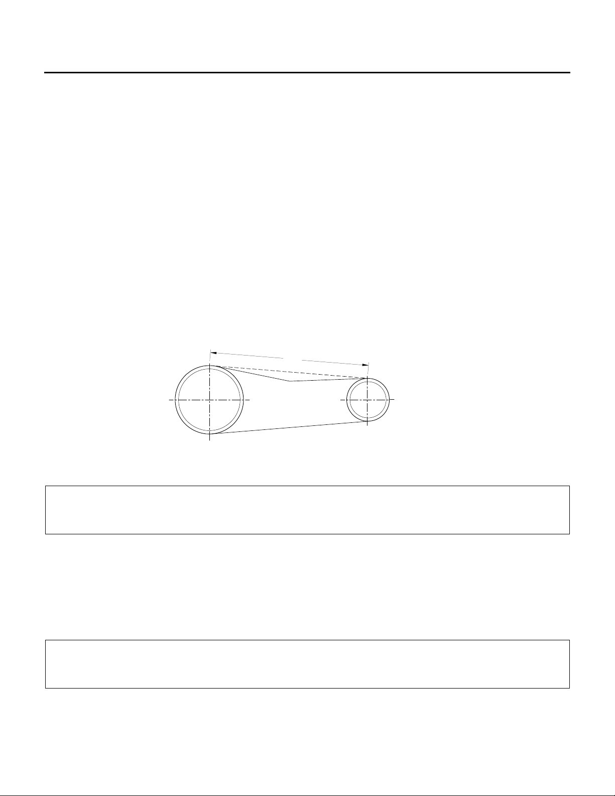
BELTADJUSTMENT
Formaximumbeltandbearinglife,pulleyalignmentandbelttensionmustbeproperlymaintained.Only
replacewithbeltsofthepropertypeandsize.
NOTE:Ifbeltsaretootightorimproperlyaligned,thelifeexpectancyofthemotor(s),fanbearingsand
belt(s)arereduced.
Alignment: Pulleysmustbealignedtowithin1/16”perfoot(1mmper760mm)ofspan.
BeltDeflection: Allow1/64”(0.4mm)ofdeflectionforeach1”(25.4mm)ofspanlength.
CAUTION:
Excessivebelttensionisthemostfrequentcauseofbeltwear,bearingwearandnoise.
SETSCREWS
Checksetscrewsonfanwheel,fanbearings,fanandmotorpulleysforloosenessontheshaft.Tighten
whererequired.Itisimportanttoperformthischeckbeforeinitialstart‐up,afterarun‐inperiodof2
weeksandthenon4monthintervals.
CAUTION:
Overtighteningsetscrewscandamagebearings.
DEFLECTION
SPAN
This manual suits for next models
1
Table of contents
Popular Accessories manuals by other brands

IFM
IFM PI2798 operating instructions

Panamax
Panamax MIW-POWER installation instructions

weinor
weinor Aruba Rund Maintenance instructions and directions for use

Enabling Technologies
Enabling Technologies DYNAMIQUE owner's manual

Omron
Omron ZN-TH11-S instruction sheet

Axminster
Axminster Woodturning D-SW Series manual


