19V(supplied from ZN-PD□□-S)
40 mA max.
-25 to 60°C
±0.3°C(at 25°C)
0.1°C
0 to 99%RH
±2.5% RH (at 25°C, 10 to 85% RH)
0.1%RH
ABS
Screw mounting
Approx. 60 g (approx. 150 g)
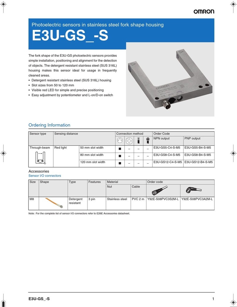
Instruction Sheet,mounting screws (M3) x 3
LED
10s
2. Communication port
1. Display
No.
1
2
3
4
5
6
7
Description
on the label
Connection
availability Yes No
Port for an optional productLabel
Mounting hole/projection
for an optional product
67.5±0.2
52.7
5.76
4.67
9.3
9.83
14Dia.
61
3
3.5Dia. MOUNTING HOLE
2-3.5Dia. MOUNTING HOLE
3
3
30.2
32.2
1.31
11
4.2
6 35
CABLE LENGTH 1m
MOUNTING SCREW HOLE
2-M3
[ UNIT : mm ]
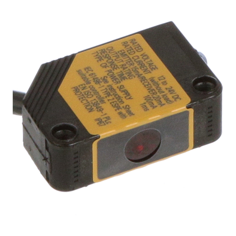
Air Thermo Sensor
ZN-TH11-S
Model
PRECAUTIONS FOR SAFE USE
PRECAUTIONS FOR CORRECT USE
Observe the following precautions to ensure safe operation.
1.
Do not use the product in atmospheres containing flammable or explosive gases.
2. Do not install the product close to high-voltage devices and/or power
devices in order to secure the safety of operations and maintenance.
3. Use a power supply of the specified voltage.
4. Do not attempt to disassemble, repair, or modify the product.
5. Do not use the product if the case is damaged.
6. Dispose of this product as industrial waste.
■Applicable standards
・EN61326-1
・Electromagnetic environment : Industrial electromagnetic environment
(EN/IEC61326-1 Table 2)
(*)When using a ZN-TH11-S alone without connecting to the ZN-PD□□-S: 12
to 24 VDC
1. Display
Notifies the Sensor's state and measurement state with indicator lighting and colors
Observe the precautions described below to prevent operation failure,
malfunctions, or undesirable effects on product performance.
1. Installation environment
Avoid installing the product in the following places:
· Places with ambient temperature that exceeds the rated temperature
· Places with ambient humidity that exceeds the rated humidity
· Places subject to corrosive or flammable gases
· Places subject to salts or iron dust
· Places subject to direct shock or vibration
· Places subject to direct sunlight or ultraviolet
· Places subject to water, oil, or chemicals
· Places subject to strong magnetic field, electric field, or charged object
· Places subject to organic substances such as benzene or spray cleaner
2. Wiring
· Lay the product cable separately from any high-voltage cable or power
line.If laid in the same conduit or duct, induction noise from them may
cause malfunction or breakdown of the product.
· Do not insert or remove connectors when power is turned ON.
3. Connection to ZN-PD□□-S Air Particle Sensor
·
The ZN-TH11-S cannot be connected to an old version of ZN-PD□□-S,
which does not comply with the ZN-TH11-S. For details, refer to
"Connecting to Air Particle Sensor ZN-PD□□-S" in this Instruction Sheet.
For information on threshold value settings, refer to the back of this
instruction sheet or the ZN-PD□□-S instruction sheet.
(*1) First, turn OFF the power supply and check the connection. If the
Sensor does not return after the restart, contact your OMRON
representative.
(*2) Do not turn OFF the power supply. Otherwise the Sensor may not be
able to work properly from the next time.
2. Communication port
Connect an ZN-PD□□-S. For information on connection, refer to "Connecting to
Air Particle Sensor ZN-PD□□-S".
* The ZN-TH11-S cannot be connected to an old version of ZN-PD□□-S, which
does not comply with the ZN-TH11-S. Availability of the connection can be checked
on the description of the label on the top face of the ZN-PD□□-S. Refer to the
table below to check the connection availability.
1. How to connect to ZN-PD□□-S
(For more information on connection settings, refer to the back of this Instruction Sheet.)
Connect a communication port of a ZN-TH11-S with a port for an optional product of
ZN-PD□□-S by ZN9-TL□□-S, which is optional connection cable.
2. How to mount ZN-TH11-S to ZN-PD□□-S
(1) Fit the hole placed at the bottom of ZN-TH11-S to the projection at the top of
ZN-PD□□-S.
(2) Fix it with the attached screw. (Tightening torque: 0.5 to 0.6 (N・m))
*In the case that ZN-PD□□-S is mounted to DIN track, mount the ZN-TH11-S to the
ZN-PD□□-S before mounting the ZN-PD□□-S to the DIN track. Otherwise
connecting the cable will be difficult.
・A humidity sensor in ZN-TH11-S senses absorption and/or desorption of moisture in the
air at the sensor surface. As performance may deteriorate through the adhesion of
impurities or contaminants in the environment on the sensor surface, calibration is
recommended once a year.
・Under normal environmental conditions, the rate of sensor accuracy degradation is:
temperature, 0.04°C per year and humidity, 0.5% RH per year. In environments where the
product is exposed to contamination like cigarette smoke or dust, replace the product
sooner.
・When ZN-TH11-S is transferred rapidly between the places that temperature difference is
big, condensation may occur on the sensor surface. In that case, the ZN-TH11-S may not
work properly. When the product becomes wet due to condensation, allow the product to
dry in a dry air, room temperature environment before use.
・When ZN-TH11-S is exposed over a long period of time at a high humidity of 80% RH or
higher, offset (+3% RH in 60 hours) may overlap with humidity. In such cases, expose the
product at room temperature and humidity for 24 hours prior to use.
・When ZN-TH11-S is exposed over a long period of time, to conditions with temperature of
under -20°C, or humidity of 90% RH or higher, deterioration of the product may accelerate.
・When not using ZN-TH11-S, store the product at a temperature of 10°C to 50°C and
humidity of 20% to 60% RH.
Port for optional product.
Do not connect to a personal
computer.
Port for ZN-RD11-S.
Personal computer can not
be connected.
■Ratings and Performance ■Connecting to Air Particle Sensor ZN-PD□□-S ■Dimensions
■
Precautions for correct use, maintenance and storage
■Part Names and Functions
Measurement
range
Measurement
accuracy
Resolution
Measurement
range
Measurement
accuracy
Resolution
Weight (in packaging)
Accessories
Measurement cycle
Operating display
Material
Mounting method
Power supply voltage *
Current consumption
Temperature
Humidity
Indicator state and color
Lights in green
Lights in red
Flashes in yellow
Flashes in light blue
Flashes in purple
Flashes in white
Lights in blue
Condition
Normal operating state
Operation error (*1)
Measured temperature exceeds the alarm
threshold.
Measured humidity exceeds the alarm threshold.
Measured dew point exceeds the alarm threshold.
Multiple items exceed the alarm threshold.
ZN-PD□□-S is in【THR】Mode. (*2)
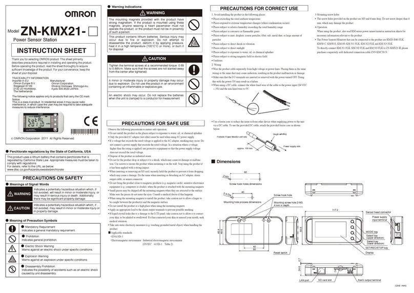
Thank you for selecting this OMRON product. This sheet
primarily describes precautions required in installing
and operating the product.
Make sure that the product is handled only by personnel
with knowledge of electrical systems.
Before operating the product, read the sheet thoroughly
to acquire sufficient knowledge of the product.
For your convenience, keep the sheet in a safe place for
easy reference.
INSTRUCTION SHEET
©OMRON Corporation 2009 All Rights Reserved.
The following notice applies only to products that carry the CE mark:
Notice:
This is a class A product. In residential areas it may cause radio
interference, in which case the user may be required to take adequate
measures to reduce interference.
Manufacturer:
Omron Corporation,
Shiokoji Horikawa, Shimogyo-ku,
Kyoto 600-8530 JAPAN
TRACEABILITY INFORMATION:
Importer in EU:
Omron Europe B.V.
Wegalaan 67-69
2132 JD Hoofddorp,
The Netherlands
Suitability for Use
s
Omron Companies shall not be responsible for conformity with any standards,
codes or regulations which apply to the combination of the Product in the
Buyer’s application or use of the Product. At Buyer’s request, Omron will
provide applicable third party certification documents identifying ratings and
limitations of use which apply to the Product. This information by itself is not
sufficient for a complete determination of the suitability of the Product in
combination with the end product, machine, system, or other application or
use. Buyer shall be solely responsible for determining appropriateness of the
particular Product with respect to Buyer’s application, product or system.
Buyer shall take application responsibility in all cases.
NEVER USE THE PRODUCT FOR AN APPLICATION INVOLVING
SERIOUS RISK TO LIFE OR PROPERTY WITHOUT ENSURING THAT THE
SYSTEM AS A WHOLE HAS BEEN DESIGNED TO ADDRESS THE RISKS,
AND THAT THE OMRON PRODUCT(S) IS PROPERLY RATED AND
INSTALLED FOR THE INTENDED USE WITHIN THE OVERALL
EQUIPMENT OR SYSTEM.
See also Product catalog for Warranty and Limitation of Liability.
Oct, 2014
D
OMRON Corporation Industrial Automation Company
Contact: www.ia.omron.com
Tokyo, JAPAN
OMRON ELECTRONICS LLC
2895 Greenspoint Parkway, Suite 200
Hoffman Estates, IL 60169 U.S.A.
Tel: (1) 847-843-7900/Fax: (1) 847-843-7787
OMRON ASIA PACIFIC PTE. LTD.
No. 438A Alexandra Road # 05-05/08 (Lobby 2),
Alexandra Technopark,
Singapore 119967
Tel: (65) 6835-3011/Fax: (65) 6835-2711
OMRON (CHINA) CO., LTD.
Room 2211, Bank of China Tower,
200 Yin Cheng Zhong Road,
PuDong New Area, Shanghai, 200120, China
Tel: (86) 21-5037-2222/Fax: (86) 21-5037-2200
OMRON EUROPE B.V.
Sensor Business Unit
Carl-Benz-Str. 4, D-71154 Nufringen, Germany
Tel: (49) 7032-811-0/Fax: (49) 7032-811-199
Regional Headquarters

