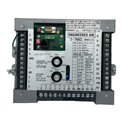
EngA C-TRAC2 User manual

A
IOM-12 Page 1 March 1999 R1
INSTALLATION, OPERATION
AND MAINTENANCE MANUAL
FOR
C-TRAC2
COOLING CONTROLLER
UNIT MODEL NO. _________________
UNIT SERIAL NO. _________________
SERVICED BY: ___________________
TEL. NO: ________________________
CANADIAN
HEAD OFFICE
AND FACTORY
USA
HEAD OFFICE
AND FACTORY
CANADIAN
EASTERN FACTORY
1401 HASTINGS CRES.
SE
CALGARY, ALBERTA
T2G 4C8
Ph: (403) 287-4774
Fx: 888-364-2727
32050 W. 83rd STREET
DESOTO, KANSAS
66018
Ph: (913) 583-3181
Fx: (913) 583-1406
1175 TWINNEY DRIVE
NEWMARKET,
ONTARIO
L3Y 5V7
Ph: (905) 898-1114
Fx: (905) 898-7244
SALES OFFICES ACROSS CANADA AND USA
Retain instructions with unit and maintain in a legible condition.
Please give model number and serial number when contacting
Engineered Air for information and/or parts.
www.engineeredair.com

AC-TRAC2.1 MANUAL
IOM-12 March 1999 R1
TABLE OF CONTENTS
I. APPLICATION ......................................................................................................... 1
II. SERVICE .................................................................................................................. 1
III. GENERAL ................................................................................................................ 1
IV. WIRING .................................................................................................................... 2
V. HEAT OUTPUT ........................................................................................................ 2
VI. SYSTEM TIMINGS ................................................................................................... 2
VII. DIP SWITCHES AND POTS .................................................................................... 2
VIII. POTS AND DIP SWITCH CHART ............................................................................ 4
IX. STATUS LIGHTS ..................................................................................................... 5
Heating Control Mode .......................................................................................................................... 5
Cooling Control Mode ......................................................................................................................... 5
Compressor Ambient Closed ............................................................................................................. 5
Internal Timer ....................................................................................................................................... 5
X. FAN CONTROL AND LOW LIMIT ........................................................................... 5
XI. CONTROL START-UP AND OPERATING STRATEGIES ...................................... 5
Heat Output .......................................................................................................................................... 5
Heat Ramp Used on the Original C-TRAC...................................................................................5
Heat Ramp Used on the Revised C-TRAC2.1 .............................................................................6
Hot Water and Steam Heating ......................................................................................................6
Simulate a Call for Maximum Heat...............................................................................................6
Economizer Control ............................................................................................................................. 6
Minimum Pot Position...................................................................................................................6
BMS Minimum Position Reset......................................................................................................7
Cooling .................................................................................................................................................. 8
Compressor Ambient Lockout.....................................................................................................8
Cooling Delays...............................................................................................................................8
To Simulate a Call for Full Cooling..............................................................................................8
XII. BURNER OPERATION ............................................................................................ 8

AC-TRAC2.1 MANUAL
IOM-12 March 1999 R1
XIII. TEMPERATURE CONTROL – GENERAL OVERVIEW .......................................... 9
Discharge Temperature Calculation .................................................................................................. 9
XIV. SENSORS AND SET-POINTS ................................................................................. 9
The Master Set-Points ......................................................................................................................... 9
The Optional Reset Inputs ................................................................................................................ 10
Night Heat ........................................................................................................................................... 10
XV. INDUCED VOLTAGE ON REMOTE CONTROL WIRING ..................................... 10
XVI. NIGHT HEAT THERMOSTATS .............................................................................. 10
Night Setback ..............................................................................................................................10
XVII. ROOM RESET THERMOSTAT OPTIONS ............................................................. 11
Options ............................................................................................................................................... 11
Reset of the Discharge Set-Point from Other Controls ...........................................................11
TE 6100-960 Set-Point Controller Connections .............................................................................. 11
Option 1 – Combination Sensor/Set-Point ...................................................................................... 11
Option 2 – Remote Discharge Set-Point with Separate Discharge Sensor .................................. 11
Option 3 – Room Sensor Only .......................................................................................................... 12
Multiple Room Sensors ..................................................................................................................... 12
TE 6100-960 Room or R/A Set-Point/Sensor c/w Dipswitch 3 “on”. ............................................. 12
4-20 ma or 0-10 VDC BMS Reset Signal ........................................................................................... 13
Calibration for BMS Configuration ................................................................................................... 13
Calibration Method 1...................................................................................................................14
Calibration Method 2...................................................................................................................14
XVIII. CALCULATED SET-POINT ................................................................................... 14
XIX. DISCHARGE TEMPERATURE SENSING ............................................................. 14
XX. SET-POINT CALIBRATION ................................................................................... 14
TE 6100-960 Johnson Controls Set-Point/Sensor Approximate Resistance ............................... 15
Sensor Resistance Chart for TE 6100-960 and TE 6000-960 .......................................................... 15
Discharge Temperature Calibration Methods ................................................................................. 15
Discharge Calibration Method 1 ................................................................................................15

AC-TRAC2.1 MANUAL
IOM-12 March 1999 R1
Discharge Calibration Method 2 ................................................................................................16
Discharge Calibration Method 3 ................................................................................................16
Discharge Calibration Method 4 ................................................................................................16
Room or Return Air Temperature Calibration Methods ................................................................. 16
Room Calibration Method 1........................................................................................................16
Room Calibration Method 2........................................................................................................16
Ambient Reset Calibration ................................................................................................................ 16
Suggested Settings Re Hunting Problems ...................................................................................... 17
LOCK-UP – Radio Frequency Interference ...................................................................................... 18
XXI. C-TRAC2.1 SET UP SHEET .................................................................................. 19
XXII. TROUBLE SHOOTING ............................................................................................. I
To Simulate a Full Call for Cooling ..................................................................................................... i
To Simulate a Full Call for Heat ........................................................................................................... i
C-TRAC2.1 Internal Operating Rules .................................................................................................. i
C-TRAC2.1 Set-Point Calculation ........................................................................................................ i
Is the C-TRAC2.1 Properly Configured? ................................................................................................... ii
Does Control Cycle through an Excessive Number of Operating Modes?.............................................ii
Voltage Noise ....................................................................................................................................... ii
Heating Trouble Shooting ................................................................................................................... ii
Overheating ...................................................................................................................................ii
No Heat..........................................................................................................................................iii
Discharge Too Cool .....................................................................................................................iii
Hunting (External Causes) .................................................................................................................... iii
H-TRAC..........................................................................................................................................iii
G-TRAC, DJM2.1...........................................................................................................................iii
DJM2 Slaving From C-TRAC .............................................................................................................. iv
G-TRAC2 .......................................................................................................................................iv
For Direct C-TRAC Control of the G-TRAC-2 ................................................................................... iv
Sensor Location ...........................................................................................................................iv
Mixed Air Dampers.......................................................................................................................iv
Possible C-TRAC2.1 Adjustments to Reduce Hunting .............................................................iv
Economizer Trouble Shooting ............................................................................................................ v
0 to 10 VDC Motors .......................................................................................................................v
Motors wired to R, B, and W terminals........................................................................................v
Economizer Not Opening .............................................................................................................v
Minimum Position is Open Too Much ........................................................................................vi
Mechanical Cooling Trouble Shooting ............................................................................................. vi
Cooling Not Running ...................................................................................................................vi

AC-TRAC2.1 MANUAL
IOM-12 March 1999 R1
Ambient Light stays On, Terminal “A” Has No Power.............................................................vii
QUICK CHECK FOR C-TRAC-2.1 NORMAL OPERATING SEQUENCE ....................... VIII
AIR CONDITIONING (Air Cooled Condenser) ................................................................. IX

AC-TRAC2.1 MANUAL
IOM-12 Page 1 March 1999 R1
A
C-TRAC2.1
COOLING, ECONOMIZER, HEAT RAMP CONTROL
If any errors or omissions are notedplease contactWade Pascoeat (403)287-4775 orFax (403)287-
4799 or (403) 243-5059.
Any reference to C-TRAC or to C-TRAC2 in the following text applies to Model C-TRAC2.1. The Model 2.1 is
similar to previous versions with the following changes:
“HD” terminal added (0-10 VDC heat output)
“ED” terminal added (0-10 VDC economizer output)
Removal of pot 6
I. APPLICATION
The C-TRAC is designed to control cooling and economizer functions on Engineered Air cooling units. It also
includes a heat output control signal.
II. SERVICE
To ensure warranty is honoured, only a qualified HVAC service person, who has received training on the C-
TRAC2.1, should be employed for service and troubleshooting. If information is required please contact the
nearest Engineered Air Office.
III. GENERAL
The C-TRAC2.1 is a discharge air temperature control that includes the option of connecting a reset control of
some type to electronically modify the discharge temperature set point.
The C-TRAC2.1 is a general purpose, multi-function controller. The C-TRAC2.1 performs the following
functions:
Modulating heat output 8.5 VDC (from HT (+) and B () terminals)
Modulating heat output 10 VDC (from HD (+) and B () terminals)
Modulating economizer output (from R, B, W terminals) for 3 wire signal to series 90 damper actuators
Modulating economizer output 10 VDC (from ED (+) and B () terminals) – 2 wire signal
Switching for 5 stages of mechanical cooling
The C-TRAC2.1 always starts in heat mode. If cooling is required it switches to economizer to satisfy
demand. If this is not adequate to satisfy demand, it switches to mechanical cooling.
The heating output supplies a DC voltage signal to operate the Engineered Air heating controllers. (G-TRAC,
G-TRAC2, DJM2, DJT-2, H-TRAC, 109 interface, 3 way mixing valves for hot water or steam heating.)
The economizer has four choices of control thereby giving maximum operational flexibility.
The mechanical cooling switching has minimum run time, minimum off time, and inter-stage timing.
Each time the C-TRAC2.1 is first powered on the H and N terminals it begins its cycle in the heat mode. How
quickly the C-TRAC2.1 will react, depends on how far the temperature at the discharge sensor is from the
calculated set point. If the call is for cooling the C-TRAC2.1 will go to the economizer operation and try to
satisfy the cooling demand. If that is not possible then the C-TRAC2.1 will bring on the mechanical cooling if
the outdoor ambient is warm enough. This process could take as much as 20 minutes to switch from the
heating mode through the economizer mode to the mechanical cooling mode.

AC-TRAC2.1 MANUAL
IOM-12 Page 2 March 1999 R1
IV. WIRING
Power supply = 24 VAC @ 0.9 amps.
The C-TRAC2.1 terminals "H and N" require a separate 24 VAC, 20 VA class 2 isolation transformer
supplying power to only "H and N". Often this is best to not have a grounded neutral as side stray voltages
can interfere with C-TRAC operation and create strange operating situations.
Terminal “N” should be wired to the neutral which is common to the same power source supplying power to
terminals (“E, A, K”). All remote wiring less than 50 feet long should be installed in clean electrical
environments and attached to terminals “Q, U, X, Y, V, Z” . Wire should be a minimum of 22 ga twisted pair
wire. (Shielded wire is best.) For longer runs and electrically noisy installations, the use of a minimum 20 gauge-
shielded wire is recommended. (Shield should be grounded at unit end only, other end taped.)
NOTE: If there is to be an interruption of only the C-TRAC2.1 power such as by a time
clock shutdown at night, there cannot be anyother load connectedtotheC-TRAC
terminals H, A, E, or K. If this wiring is not correct there may be about 18 volts on
any components attached incorrectly when the C-TRAC2.1 has power turnedoff.
This is the result of a feedback voltage which may cause certain output signals to
stay energized. (E.g. It may keep a fan delay relay energized to keep fan running when
not required.)
V. HEAT OUTPUT
The C-TRAC2.1 has a 0-10 VDC output ramp from terminals “HD and B”, which can be used to control gas
heat controls (DJM2, DJT2, G-TRAC, G-TRAC2, 109 Interface), electric heat (H-TRAC) or water coils, etc.
VI. SYSTEM TIMINGS
The C-TRAC2.1 has two built in timing circuits.
1. Timing from heat to economizer to mechanical cooling modes varies depending on the error between
calculated set point and actual discharge temperatures.
2. Inter-stage minimum run and minimum off time for compressors is 4 minutes.
VII. DIP SWITCHES AND POTS
The C-TRAC2.1 uses a number of dipswitches and pots to set the parameters it will look at to set its control
set point at. They are set at the factory to "customize" the control for its particular application on each unit.
Changing any of these settings can destroy the control capability for your particular system.
Option 1. Discharge air control. (Only dipswitch 1 on.)
Option 2. Not used – for test purposes only. (Only dipswitch 2 on).
Option 3. Discharge air control with room or return air reset. (As the room warms up the discharge
temperature falls. Dipswitch 1 and 3 on, reset wired to “V, X, Y and Z”).
Option 4. Discharge air control with ambient and/or VAV reset. As the airflow increases or the ambient
temperature increases the discharge temperature will be set downwards. (Dipswitch 1 and 4 on,
resistor network wired to “V, X, Y, and Z”).
Option 5. Discharge air control with the BMS reset signal of 4-20 ma or 0-10 VDC modifying the
discharge temperature. (As the signal strength increases above 12 MA or 5.5 VDC the discharge
temperature is driven warmer; as the BMS signal falls below 12 MA, 5.5 VDC the discharge
temperature is driven colder. Dipswitch 1 and 5 on, BMS reset wired to + and -).
NOTE: At approximately 5.5 VDC or 12 ma input from theBMS therewould be noreset occurring.
As the BMS input voltage deviates from this voltage, the C-TRAC2.1 will reset the
discharge up or down.
The C-TRAC2.1 dipswitches will be set for operation as per the following table:

AC-TRAC2.1 MANUAL
IOM-12 Page 3 March 1999 R1
Option SW1 SW2 SW3 SW4 SW5 REMARKS
1 On Off Off Off Off Discharge control
2 Off On Off Off Off Room control (not recommended)
3 On Off On Off Off Discharge control c/w room or return reset
4 On Off Off On Off Discharge control c/w ambient reset
5 On Off Off Off On
Discharge control c/w 4-20 ma, 0-10 VDC
BMS reset or inlet vane position reset on
supply fans
The above systems that have a room sensor/set-point can have a night setback to lock off the mechanical
cooling and economizer and reduce the heating set point at night. The setback is activated when C-
TRAC2.1 terminal K has 24 VAC applied to it. During the time terminal K is powered, the discharge sensor
is locked off so the C-TRAC control is just from the space sensor/set point. If the sensor is in the return air
the supply fan must be turned on for the sensor to be able to sense space temperature.
To repeat, the pre-selected options are set at the factory by setting the dipswitches and pots. If the settings
are not correct the C-TRAC2.1 will not be able to function as designed due to the logic chip receiving
incorrect information.
On the following page is a list of adjustment pots on the C-TRAC.
First, note the newer C-TRAC2.1 does not have a P6 pot. Refer to page 6 for more information.
Second, in addition to the pots under the cover on the front of the C-TRAC, there are additional pots
located on the back of the C-TRAC. The control needs to be moved off the back wall to access these pots.
P8 Room or ambient reset deadband (refer to page 19 for more information).
P9 BMS or valve reset (refer to page 19 for more information).
P10 BMS calibration (refer to page 19 for more information).
P11 Heating control band setting (refer to page 19 for more information).

AC-TRAC2.1 MANUAL
IOM-12 Page 4 March 1999 R1
VIII. POTS AND DIP SWITCH CHART
P1 NIGHT SETBACK
To adjust the amount of heat for
night below the room dial set point,
first terminal “k” must be powered
with 24 VAC on it. This locks off
mech. cooling, econo and lowers
the room heat by the temp set on
pot.
NOTE: You need room sensor.
P2 DISCHARGE
CALIBRATION
To calibrate the set point dial on the
front of the C-TRAC2.1. To use this,
“S” and “SP” must be jumped. If an
external set point is wired to U, S,
and M this is still the calibration pot.
There will be no “S-SP” jumper with
external set point.
P3 COOLING DEADBAND
To adjust range in which discharge
temp. will not switch cool stages.
P4 CALIBRATION FOR ROOM
RESET
If the optional control is wired to
terminals V, Y, X, Z.
P5 ROOM RESET FACTOR
Adjusts amount of control the room
thermostat has.
1 = maximum reset
5 = minimum reset
P6 HEAT OFFSET FACTOR
N/A on C-TRAC2.1.
On older C-TRAC’s this pot sets
deadband between heat and cool
set point (heat output terminal HT and
B). This ramped output is also
affected by cooling deadband and
type of heat control in use.
5 = min. offset
1 = max. offset
P7 DAMPER MIN. POS. POT
Note: Some units may use
external pot.
SWITCHES
1 to 5 selects option set point and
sensors.
To test Discharge Air Control only
switch 1=on, switches 2 through
5=off.
To test Room Control only
Switch 1 = off
Switch 2 = on
Switches 3 through 5 = off
Switches 6 and 7 are for
economizer set up.
SWITCH 8 IS TO SHORTEN
MECH. COOLING TIMERS
ENSURE ITS LEFT IN THE OFF
POSITION WHEN YOU FINISH
SERVICING.
LED LIGHTS
C-TRAC2.1 always starts in heat
mode.
HEATING – light on, in heat
mode.
NO HEAT OF COOL LIGHT –
Economizer operation.
COOLING – light on, in cool
mode.
INT. TIME DELAY LIGHT ON –
The discharge temp is not
satisfied and the microprocessor
is going to switch mode or adjust
an output.
COMP. AMBIENT CLOSED
Outside ambient will allow mech.
cooling to operate.
TO SIMULATE A FULL CALL
FOR COOLING
Open circuit discharge sensor.
TO SIMULATE A FULL CALL
FOR HEAT
Short circuit discharge sensor.
12
10
14
68
2
3
1
54
2
3
1
54
50
25
75
100 0
Colder
Hotter
6
9
5
13
11
7
8
Colder
Hotter

AC-TRAC2.1 MANUAL
IOM-12 Page 5 March 1999 R1
IX. STATUS LIGHTS
The C-TRAC2.1 has 4 status lights.
Heating Control Mode
This light is on whenever the C-TRAC is in the heat mode (the C-TRAC2.1 always starts in heat mode).
Cooling Control Mode
This light is on whenever the C-TRAC is in mechanical cooling mode.
NOTE: If neither the heat nor cool light is on, the C-TRAC is in economizer mode.
Compressor Ambient Closed
This light is on whenever an externally mounted ambient control places 24 VAC on terminal “A”.
Internal Timer
If this light is off when the C-TRAC was power, the control is satisfied and the C-TRAC calculated set point
and discharge temperatures are very close to each other. If it is on, the error between calculated set point and
discharge temperature sensor is such that the control is timing to either change mode or increase/decrease
the heat/economizer/mechanical cooling output.
X. FAN CONTROL AND LOW LIMIT
These functions are not controlled by the C-TRAC2.1. Other devices, external to the C-TRAC2.1, supervise
fan control and low limit.
XI. CONTROL START-UP AND OPERATING STRATEGIES
The C-TRAC2.1 will always try to satisfy the discharge temperature. If the C-TRAC2.1 is unable to satisfy the
discharge temperature in its current operating mode (heating, economizer or mechanical cooling) then it will
switch into the next operating mode. Depending as to how far the discharge temperature is from the
calculated desired discharge temperature determines how quickly the C-TRAC2.1 will switch to a different
operating mode or adjust the output in the mode it is presently in. There are three operating modes:
Heating (heat light is on)
Economizer (usually neither heat or cool light is on, the exception being constant economizer dipswitches 6 and 7
are off)
Mechanical cooling (cool light is on)
NOTE: Remember the C-TRAC2.1 will always power up in the heating mode.
When the C-TRAC is in mechanical cooling mode and the compressors are in operation, if the ambient
control removes power from terminal A then the C-TRAC will go directly to heating mode. If there is no call for
heat and the calculated set point wants cooling, it will return to economizer mode in a few minutes, then
mechanical cooling.
Heat Output
The C-TRAC2.1 always powers up in the heat mode. There are two possible heat output ramps to wire to
depending on the application.
Heat Ramp Used on the Original C-TRAC
The heat output control voltage is across terminals HT and B. The voltage varies from 0 VDC for no heat call,
0.75 for low heat call, modulating through to 8.5 VDC for high heat call. Note that certain older controls
require a resistor network to reduce control voltage (such as the original DJM which, if not for the resistor network,
would be at high fire when there is greater then 4 VDC from the C-TRAC HT and B terminals).

AC-TRAC2.1 MANUAL
IOM-12 Page 6 March 1999 R1
Heat Ramp Used on the Revised C-TRAC2.1
This revision was made to Model C-TRAC2.1 in the spring of 1996. It has a 0 to 10-volt heat output ramp to
modulate different heating controls (G-TRAC, G-TRAC2, DJM2.1, H-TRAC, etc.) The 0 to 10 VDC modulating
output signal comes from the C-TRAC2.1 new terminal “HD” (Positive) and the existing “B” terminal (negative).
Hot Water and Steam Heating
The heat output ramp can also be used to drive 2-way or 3-way mixing valves on hot water or steam coils on
air handling units. These can be reverse or direct acting depending on piping and wiring of the mixing valves.
Note that the output of the C-TRAC is not reverse acting. A resistor bridge network is required for actuators,
which drive the above valves. Actuators can be 3 wire or 2-wire type.
Simulate a Call for Maximum Heat
To simulate a call for maximum heat jump the discharge sensor connections Q and M and place the C-
TRAC2.1 dip switches in the following positions. If the C-TRAC2.1 is in any other mode than heat at the time
you perform this function, turn the power to the C-TRAC2.1 "off " for 10 seconds, then turn it back on. This will
enable a faster response, as you will not need to wait for as many internal mode time delays.
1 - on
2 - off
3 - off
4 - off
5 - off
This has the C-TRAC2.1 operating strictly as a discharge air controller and the jumper forces the control to
call for full heat, as its sensor input is now always cold.
Pots that affect the heat control on the original C-TRAC are pots 3, 6, and 11. The proper settings depend on
the type of heating controller in use and the set point of the cooling deadband pot 3. Pot 6 does not exist on
the newer C-TRAC2.1 (it is a fixed value).
Pot 11 (on both original and new C-TRAC) is the heat envelope pot. It is set to suit the type of heat exchanger
and heat control being used.
(On the original C-TRAC, pot 6 is the heat offset pot. This acts similar to the Honeywell T872 room thermostat as it sets
up a deadband between the two levers. The C-TRAC pot 6 setting is from 5 to 0. When it’s set at 5 there is very little
offset and when its at 0 the heat set-point is at its furthest below the cooling set-point [the set-point on the knob].)
Economizer Control
Many units today use multiple 0 – 10 VDC direct acting motors. Most of these do not require shunt resistors.
The original C-TRAC had one economizer signal. It operates Honeywell series 90 motors from the “R, B”, and
“W” terminals on the C-TRAC and modulates the dampers by placing a slightly unbalanced voltage on the
damper motor terminals “R, B”, and “W”.
The C-TRAC2.1 has added a 0 to 10 VDC economizer ramp. This will usually be operating the newer direct
drive motors on the market today. There is a modulating output from terminals “ED” (positive) and “B”
(negative). Zero volts is minimum position, ten volts is full fresh air.
If the discharge temperature is too hot the C-TRAC2.1 will energize the economizer after passing through the
heating mode time delay. The length of time depends on the urgency of the overheating call. Typically this
delay will be from 4 to 10 minutes.
The damper motor is normally on its own ungrounded isolated transformer.
The C-TRAC2.1 will use the economizer as another device to maintain the calculated discharge temperature.
Minimum Pot Position
Pot 7 is the minimum position pot. When it is used it can be adjusted from 0 to 100% opening. The usual
setting is in the 10% area if no other set point is specified. Note that the minimum position pot on the C-
TRAC2.1 is not always in use. There are instances where a separate minimum position pot is being used. If a
separate minimum position pot is being used it is usually located in the damper motor and pot 7 should be left
at 0 position.

AC-TRAC2.1 MANUAL
IOM-12 Page 7 March 1999 R1
BMS Minimum Position Reset
Some applications require that BMS systems take control of the minimum OA position for smoke control or to
maintain building static by supplying a 0 – 10 VDC signal to the C-TRAC 2.1. This method would require a
diode to be placed on ‘ED’ terminal and another diode on remote signal wire to eliminate feedback problem.
(See drawings).
NOTE:Fieldanalogcontrolinputsrequiresignalisolationtopreventground
loopsignalcorruptionand/ordamagetothecontroller(s).
SAMPLE WIRING FOR 0 – 10 VDC MOTORS
1
E
R
W
B
ED
R W
HIGH AMBIENT SET BACK AT
75° (23°C) R-w CLOSES ON
RISE
ENG A C-TRAC
CONTROL
2
1
3
2
1
3
0 – 10 VDC
DAMPER
OPERATOR 24V UNGROUND XFMR
MAY HAVE
MULTIPLE
OPERATORS
0 – 10V DC ECOMOMIZER OPERATORS
-
+
24V UNGROUND XFMR
R W
0 – 10V DC ECONOMIZER OPERATION
WITH EXTERNAL 0 – 10VDC SIGNAL OVERRIDE
NOTE: UNGROUNDED TRANFORMER IS REQUIRED FOR C-TRAC CONTROLLER WHEN 0 – 10 VDC DAMPER OVERRIDE SIGNAL
BY OTHERS IS USED.
2
H
N
E
K R
W
A
C
B
ED
1
2
C1
C1
2
1
3
2
1
3
0 – 10 VDC
DAMPER
OPERATOR
MAY HAVE
MULTIPLE
OPERATORS
120/24V/20VA
Unground XFMR
NIGHT
CONTACT
High Ambient
Setback at 75F
(23C R-W Closes
on Rise
Low Ambient
Control at 50F
(10C) R-W Closes
on Rise
24V or 120V Power
Supply from Main
Transformer
EngA C-
TRAC
CONTROL
1LPC
1HPC
2LPC
2HPC
0 – 10 VDC
Damper Override
Signal by Others
DIODE
DIODE
H
N
R W
HIGH AMBIENT
SET BACK AT 75°
(23°C) R-w
CLOSES ON RISE
DAMPER
ON/OFF
CONTACT
=
E
R
W
B
ED
ENG A C-TRAC
CONTROL USING
A
REMOTE MIN. POS.
POTENTIOMETER
2
1
3
2
1
3
0 – 10 VDC
DAMPER
OPERATION
24V UNGROUND XFMR
MAY HAVE
MULTIPLE
OPERATORS
2
3
4
1
=
REMOTE
SGA24
MINIMUM
OUTSIDE
POSITIONER
3
FOR CONTINUOUS ECONOMIZER
OPERATION SWITCHES 6 AND 7 TO
BE ‘OFF’.
R B
REMOTE MINIMUM OUTSIDE AIR POSITIONER
C/W 0 – 10 V DC ECONOMIZER OPERATORS
E
R
W
B
ED
ENG A C-TRAC CONTROL
DOES NOT USE INTERNAL
MINIMUM POSITION
POTENTIOMETER
2
1
3
0 – 10 VDC
DAMPER
OPERATION 24V UNGROUND XFMR
2
1
3
MAY HAVE
MULTIPLE
OPERATORS
4
Z
V
VVVVVVVVVV
R B
-
+
=
DAMPER
ON/OFF
CONTACT
10K MIN.
POS. POT.
MOUNTED
IN
CONTROL
CABINET
FOR CONTINUOUS ECONOMIZER OPERATION SWITCHES 6 AND 7 TO BE OFF
CONTINUOUS 0 – 10 V DC ECONOMIZER OPERATOR c/w OUTSIDE
AIR MINIMUM POSITION POTENTION MOUNTED IN CONTROL
C
ABINET
HIGH AMBIENT
SET BACK AT
75° (23°C) R-
w
CLOSES ON
RISE

AC-TRAC2.1 MANUAL
IOM-12 Page 8 March 1999 R1
The economizer is to be configured to one of the following operation modes:
1. Dampers go to minimum fresh air position whenever the first compressor starts. (Dipswitch 6 OFF and
dipswitch 7 ON.) 1 and 2 (dip switches 6 and 7 are both ON).
2. Dampers go to minimum fresh air position whenever the outside enthalpy or the outside temperature is high.
(Dipswitch 6 is ON and dipswitch 7 is OFF with a 24-volt ac input to terminal E).
NOTE: The power applied to terminal E must be from the same source as the power supply to the
C-TRAC2.1 terminal H.
3. A combination of 1 and 2 (dip switches 6 and 7 are both ON).
4. Constant compressor load (dip switches 6 and 7 are both OFF). In this mode of operation the C-TRAC2.1 will try
to operate with maximum outside air. If the cooling demand drops off, instead of shutting off a compressor, it
will first throttle back the inlet air damper. If there is still not enough load in the return air the compressor will
be cycled off. This will maintain a more constant compressor load and keep the discharge temperature
satisfied while minimizing compressor cycles. Operation in this mode will require an external economizer
ambient lockout and separate minimum position pot. For the 0 – 10 VDC 2 wire damper motor signal a 10K
OHM pot is used externally or the SGA24 remote minimum pot can be used externally. When a 10K OHM
pot is used ensure that the diodes are placed in proper ‘bias’. (See drawing for various options). For the 3 wire
Honeywell damper motors wired to RBW a minimum position pot such as Q209 or S9638 is used.
Cooling
Compressor Ambient Lockout
The mechanical cooling cannot operate unless the outside ambient is above a pre-selected limit. The ambient
control is a separate control that is wired to the C-TRAC2.1 terminal A. When the outside temperature is above
the set-point of the ambient control then a 24 VAC signal is applied to terminal A. The C-TRAC2.1 is able to cycle
on the cooling stages.
NOTE: Use the same 24 V power on terminal A as is being used to power the C-
TRAC2.1 terminal H.
The discharge air set point is the same for both the economizer and the mechanical cooling.
Cooling Delays
The C-TRAC2.1 contains time delays for minimum run, minimum off, and inter-stage timing. These delays are all
a non-adjustable 4 minutes. For service purposes turning on dip switch 8 can shorten the above delays.
NOTE: This switch must be left in the off position during normal operation. If it is left ‘on’it
may result in compressor failure or lack of control stability.
In addition to the above delays there may also be a cooling integral demand delay. This delay is calculated by the
C-TRAC2.1 based on time and demand. This delay is non-removable and ranges in time from 1 to 8 minutes.
If the compressor ambient control is switched while compressors operating, the C-TRAC 2.1 will switch to heating
mode as it thinks that the ambient was too cold for compressors to run!
To Simulate a Call for Full Cooling
To simulate a call for full cooling open circuit the discharge air sensor by removing the wires from either “Q” or
“M”.
XII. BURNER OPERATION
Burner operation is supervised by controls outside the C-TRAC2.1. In many applications the C-TRAC2.1 will
supply a modulating 0-10 VDC signal to control the burner control module (i.e. DJM, G-TRAC, etc.) which in
turn modulates the burner.

AC-TRAC2.1 MANUAL
IOM-12 Page 9 March 1999 R1
XIII. TEMPERATURE CONTROL – GENERAL OVERVIEW
Discharge Temperature Calculation
NOTE: Ifany resetsare not connected but the switch is on, the dischargetemperature will
be affected. This is especially true of BMS systems that have notbeen wired inbut
the control was specified for it.
The C-TRAC2.1 is designed primarily as a discharge air control. However, the discharge temperature can
be reset up or down if a reset control is connected to the system. The C-TRAC2.1 has the ability to modify
the discharge temperature by any of the following:
The temperature at the optional room sensor.
The temperature at the optional return air sensor.
The temperature at the optional outside air sensor.
The position of an optional VAV damper sensor.
An input signal from a Building Management System (BMS).
If any optional reset controls are used, a calculation is done by the C-TRAC2.1 to select the corrected
discharge temperature to satisfy the conditions of all the sensors and set points.
NOTE: The reset can drive discharge temperatures up more then down in all applications
(e.g. up 20 or down 7) except BMS (which will reset equally up 20, down 20).
Example:
In all applications there is a discharge sensor and a discharge set point. We will assume a 55ºF
discharge set point. If no other control were activated on the C-TRAC2.1 it would maintain a 55º
discharge. If, however, there were an optional room sensor at 69º and a remote room set point at
72º, then the space needs less cooling. The calculated discharge temperature would be adjusted
up to a higher temperature to conserve energy and avoid overcooling the space.
If the room sensor temperature rose to 75º and the remote room set point is at 72º then the C-
TRAC2.1 will bring on more cooling to cool the space.
If the C-TRAC has any reset option enabled, the discharge set point should not be set below 60ºF
as the reset could drive the discharge temperature very low.
The amount and rate of the reset depends on the authority given to the room control by the room
reset factor pot (pot 5) and how far the room and discharge temperatures are from their respective
set-points.
XIV. SENSORS AND SET-POINTS
The C-TRAC2.1 is designed to operate with JOHNSON CONTROLS TE 6000-960 sensors and TE 6100-
960 sensor/set-point dial or equivalent. This is nearly linear from 40 to +140ºF. Following is a resistance
temperature graph (Page 15).
If a JOHNSON CONTROLS TE 6100-960 combination sensor set point is used, it is not necessary to use
both functions at the same time. In fact many applications use only the sensor or the set-point function in a
"remote" application.
The Master Set-Points
The master discharge air set point is the same for both the economizer and the mechanical cooling. The
heating set point is offset below the cooling set point. (This is similar to the offset between the levers on a T874
thermostat, which allows a deadband between the two set points. The deadband will not allow the control to cycle
between the heating and cooling.) This procedure is covered in the HEAT OUTPUT section.
As a MASTER SET POINT, the C-TRAC2.1 is designed to use either:
The set point mounted on the face of the C-TRAC2.1 (range of 10-35ºC or 52-95ºF). If the C-TRAC2.1
face mounted set-point is used, terminals “SP and S” must be jumped, or;
The Johnson TE 6100-960 set point (range of 50-85ºF and usually remote mounted). If the TE 6100-960 is
used as a set-point, “S to SP” are not jumpered and the TE 6100 must be wired to U, S and M:

AC-TRAC2.1 MANUAL
IOM-12 Page 10 March 1999 R1
TE 6100 Wires C-TRAC2.1 Terminals
Violet (not used, sensor)
Blue M
Orange S
Grey U
Red (not used) Q
(No jumper S-SP)
The Optional Reset Inputs
May be controlled from room temperature, ambient temperature, voltage, or current input. The BMS
voltage/current, room and ambient temperature resets will reset SPC in both directions.
The resets permit electronically changing the “calculated set-point” if external reset devices are wired
correctly and the appropriate dipswitches are configured correctly. The “calculated or operating discharge
air set-point” is the mathematical addition of the master set point and one optional reset signal.
If an ambient room override set point is used it is wired to the “Z, X, Y”, and “V” terminals. This is used on
any override except the BMS control or a VAV system.
The BMS reset does not have a set point on the C-TRAC2.1. It is controlled from the BMS system. Refer to
Section XVII.
Night Heat
In addition the control can be activated for night heat if configured and wired correctly. See below for
details. Night heat operates best on units with return air. Night heat is not as compatible with units designed
to operate as 100% "make-up air" because at night the unit will have to open the outside air dampers and
heat outside air, which is not truly cost effective. If there is a modulating or single stage room thermostat
connected to terminals “X, V, Y, and Z” the night heat function will be activated when terminal “K” is
powered.
The only exception to “discharge air control” is when the C-TRAC2.1 is wired to provide space temperature
control at night (OPTIONAL). During this night time operation the discharge sensor acts as a modulating
high limit and controls discharge air temperature to approximately 110ºF to 140ºF.
XV. INDUCED VOLTAGE ON REMOTE CONTROL WIRING
Following are a number of discharge temperature reset methods. This also applies to remote set points,
sensors, etc. When any of these are ordered at the time the unit is manufactured the control is calibrated at
the factory and this calibration will satisfy most applications unless resistance from long wiring runs or
induced voltage on the remote wiring cause it to be out of calibration. (To check for induced voltages,
disconnect all of the field wiring in question from the C-TRAC2.1 while the unit is operating, and check for AC volts
across each questionable wire and ground.)
XVI. NIGHT HEAT THERMOSTATS
Requires TE 6100-960-room thermostat c/w dipswitch 3 to be “on”. When terminal “K” is powered, cooling
functions are disabled (i.e. no economizer or mechanical cooling). The TE 6100-960 set point is then set back
a number of degrees as selected by pot 1 NSB (night setback). Heat is fired and maintained around a point
between 110ºF to 140ºF as the TE 6000-960 discharge air sensor starts to conduct and operate as a
modulating high limit.
Night Setback
Night setback is initiated by energizing terminal K with 24 VAC.
NOTE: Use the same 24 VAC power that is used to power the C-TRAC2.1. This terminal
will lock off the mechanical cooling and the economizer when it is activated.
During night setback the room temperature will be lowered by an adjustable amount as set on the C-
TE 6000 Sensor

AC-TRAC2.1 MANUAL
IOM-12 Page 11 March 1999 R1
TRAC2.1 pot 1 (NSB). The discharge sensor is locked off at night and control is from the room
sensor/set-point only.
NOTE: The room sensor must be present for this option to operate. (It also requires that
dipswitch 3 is on for night setback to operate.)
If there is a call for heat at night the discharge sensor will act as a discharge air modulating high limit.
This is not field adjustable and will vary between 120 and 150F. Due to heat lag at the sensor it may
be possible that the control high limit may cycle the heater on and off.
XVII. ROOM RESET THERMOSTAT OPTIONS
Options
Reset of the Discharge Set-Point from Other Controls
Room Reset
Return Air Reset
Outside Ambient Reset
VAV Reset
0 to10 VDC or 4 to 20 ma Reset
TE 6100-960 Set-Point Controller Connections
When using the numbers TE 6100 and TE 6000 note that they are a Johnson Controls part number.
There are controls from other suppliers with different part numbers that may be substituted. The values
must be equivalent to the Johnson line.
The TE 6100-960 can be used for two functions. The first is as a discharge temperature set point, for
which it will be wired to terminals “M, S”, and “U”. The second use is to reset the discharge temperature
from either space or outdoor ambient temperatures. In this application it will be wired to terminals “V, Z,
X” and “Y”. Refer to the unit-wiring diagram to determine the usage of any TE 6100-960.
A discharge set-point knob on the front of the C-TRAC2.1 is usually used as the set point. If it is in use
the C-TRAC2.1 terminals “S” and “SP” will have a jumper across them.
NOTE: If a TE 6100-960 is being used as a remote discharge set-point, the “S”and “SP”
terminals on the C-TRAC2.1 will not be jumpered.
Option 1 – Combination Sensor/Set-Point
If the TE 6100-960 is being used as a room reset device it is usually used as a combination sensor/set-
point.
TE 6100 WIRE COLOUR C-TRAC2.1 TERMINAL PURPOSE
Room reset sensor/set-point
Blue V Room reset set point +
Grey Z Room reset set point
Orange Y Room reset centre tap
Violet X Room sensor
Option 2 – Remote Discharge Set-Point with Separate Discharge Sensor
Although two separate controls can be employed (one as the sensor in the space and one as a reset set point
located in a room where it cannot be tampered with).
TE 6100 WIRE COLOUR C-TRAC2.1 TERMINAL PURPOSE

AC-TRAC2.1 MANUAL
IOM-12 Page 12 March 1999 R1
Discharge sensor/set-point
Blue M Discharge set-point +
Grey U Discharge set point
Orange S Dis. S.P. centre tap
NOTE: Do not use the sensor (violet wire) on the TE 6100-960 if it is being used only as a
remote discharge set point.
Use a separate TE 6000-960 sensor for a discharge sensor
Violet M Discharge sensor +
Violet Q Discharge sensor
Option 3 – Room Sensor Only
If the TE 6100-960 is being used as a room sensor only use the violet and blue wires.
Multiple Room Sensors
Four sensors can be wired to give an average reading of room temperatures to the TRAC control. They
must be wired in a series/parallel arrangement. The drawing above drawing shows a circuit making use of
the built in sensor in the TE6100 Johnson Sensor/Setpoint assembly and using TE6000 sensors for the
other three. (The other three could also be TE6100, just using the sensor wires .)
TE 6100-960 Room or R/A Set-Point/Sensor c/w Dipswitch 3 “on”.
TE
6000
TE6000
Grey
X
V
Y
Z
Orange
Blue Built in
TE6100
TE6000
Violet

AC-TRAC2.1 MANUAL
IOM-12 Page 13 March 1999 R1
Room stat satisfied Unit controls discharge temperature as per
discharge set point.
Room temp. colder than set-point
Unit controls discharge temperature as per discharge
set point plus selectable amount on pot 5 (room-reset
factor).
Room temp. hotter than set-point
Unit controls discharge temperature as per discharge
set point minus selectable amount on pot 5 (room-
reset factor).
4-20 ma or 0-10 VDC BMS Reset Signal
Discharge air control with the BMS reset signal of 4-20 ma or 0-10 VDC modifying the discharge
temperature. (As the signal strength increases above 12 MA or 5.5 VDC the discharge temperature is driven
warmer; as the BMS signal falls below 12 MA, 5.5 VDC the discharge temperature is driven colder.)
NOTE: At approximately 5.5 VDC or 12 ma input from theBMS therewould be noreset occurring.
As the BMS input voltage deviates from this voltage, the C-TRAC2.1 will reset the
discharge up or down.
NOTE: If the control is set up for a BMS signal and that signal is not connected, the C-
TRAC will interpret the lack of voltage as a full call for reset downwards. If the
BMS signal is not connected the BMS dipswitch should be off.
The BMS signal is wired to the optically isolated “+” and “” terminals.
Pots 9 and 10 relate to BMS reset. As described below, pot 10 is the calibration pot.
Pot 9 determines the amount of authority being given to the BMS reset. Setting "2" allows ±4º and setting
"5" allows as much as ±25ºF on a 0 to 10 VDC system (±20º on a 4 to 20 ma system).
Calibration for BMS Configuration
Set dipswitch 1 "on", and dip switches 2, 3, 4 and 5 "off".
Calibrate the discharge sensor first using the method below.
Approximate relationship between 0-10 VDC and 4-20 ma signal is:
Pivot
Point
RESET CONTROL
Discharge Temperature
Warm Discharge
Manual Discharge Set Point
Cool Discharge
Room Hot
Room Cold
Room Temperature
Room Set Point

AC-TRAC2.1 MANUAL
IOM-12 Page 14 March 1999 R1
VDC Ma
0 0
2 3
Note: Zero reset considered tobe about 5.5 VDC
or 12 ma less is resetting down to cooler
discharge greater is resetting up to warmer
discharge
4 8
5 10
6 12
8 16
10 20
Calibration Method 1
Remove the discharge sensor and install a 1000-ohm 1% ¼ watt resistor in place of the sensor.
Adjust the discharge set point until the internal time delay activated light goes off, and is mid way
between the two on points. Set the incoming signal to either 12 ma or 5.5 VDC. Turn on dipswitch 5.
Gradually adjust pot 10 (mounted on the underside of the board) until the internal time delay activated
light goes off, and is mid way between the two on points.
Calibration Method 2
Install the temperature simulator pot and adjust the simulator temperature pot until the internal time
delay activated light goes off, and is mid way between the two on points. Set the incoming signal to
either 12 ma or 5.5 VDC. Turn on dipswitch 5. Gradually adjust pot 10 (mounted on the underside of the
board) until the internal time delay activated light goes off, and is mid way between the two on points.
XVIII. CALCULATED SET-POINT
The calculated set point is an internal calculation of the C-TRAC electronics. If no reset devices are
activated (dipswitches 2, 3, 4, 5 are off). The calculated set point and set point knob are the same value. If,
however, one of the reset functions is activated, the calculated set point also includes the affect of that
reset devices desire to adjust the set point up or down.
XIX. DISCHARGE TEMPERATURE SENSING
A duct sensor senses discharge temperature. There are often two discharge sensors on the C-TRAC, one
for heat control and one for cool control. A relay will switch between them. This is to avoid hunting
problems introduced by the thermal mass of the cooling coil.
XX. SET-POINT CALIBRATION
Set point calibration should not need to be done as it was set at the factory. The Johnson Control TE 6000-
960 and the TE 6100-960 combination set point and sensor is pre-calibrated at Johnson's factory. The
Engineered Air C-TRAC2.1 has been calibrated at the Engineered Air factory.
1. To determine what control options this C-TRAC is configured to operate with check the wiring diagram,
control function, or C-TRAC dipswitch settings. The types of control are listed below.
2. Locate the dipswitches under the removable cover. Write down their present settings. After calibration
return the switches to their original settings.
SW1 SW2 SW3 SW4 SW5 REMARKS
On Off Off Off Off Discharge control
Off On Off Off Off Room control (not recommended)
On Off On Off Off Discharge control c/w room or return reset
On Off Off On Off Discharge control c/w ambient reset
On Off Off Off On Discharge control c/w 4-20 ma, 0-10 VDC or
vane position reset
Calibrate the required individual sensor and set points combination in the following order. Do not attempt to
calibrate any application listed below that is not part of your application.

AC-TRAC2.1 MANUAL
IOM-12 Page 15 March 1999 R1
1. Discharge (first).
2. Room, return, or ambient (second).
3. Current, voltage, or vane position (last).
TE 6100-960 Johnson Controls Set-Point/Sensor Approximate Resistance
SENSOR (purple and blue) Same resistance as TE 6000-960
Set-Point Dialled To
60 degrees 90 degrees
POT
(orange and grey) 2.725 K 3.272 K
(orange and blue) 3.184 K 2.702 K
(blue and grey) 970
OTHER (purple and orange) 4.19 K 3.71 K
(purple and grey) About 1.981 K (varies with element temp.)
Sensor Resistance Chart for TE 6100-960 and TE 6000-960
°C °F Resistance °C °F Resistance °C °F Resistance
-40 -40 602-605 18.3 65 983 48.9 120 1234
-34.4 -30 633 20 68 996 54.4 130 1269
-28.9 -20 665 20.6 69 1000.7 60 140 1333
-23.3 -10 698 21.1 70 1005 65.5 150 1365
-17.8 0 732 23.9 75 1026.5 71.1 160 1437
-12.2 10 768 26.7 80 1048 76.7 170 1491
-8.7 20 804 29.4 85 1070 82.2 180 1546
-1.1 30 842 32.2 90 1092 87.7 190 1602
4.4 40 881 35.6 95 1116 93.3 200 1659
10 50 921 37.8 100 1139 98.8 210 1718
12.8 55 941.5 43.3 110 1186 100 212 1778
Reference resistance is 1035 ohms at 77°F. Resistance tolerances are ±0.05 to 0.15% at 77°F. Temperature range +32 to +104°F.(TE 6100-
960 pot is 53C3, 500R, 7/8 by ¼ shaft.)
NOTE: Engineered Air’s design discharge temperature range is 30 to 140ºF.
Discharge Temperature Calibration Methods
Where the following text calls for a resistor to be substituted into the circuit it must be a 1% tolerance
resistor.
Discharge Calibration Method 1
Ensure dipswitch 1 is "on".
Set dipswitches “2, 3, 4”, and “5” to the "off" position. This disables all set-point resets. You are
now in discharge control mode only.
Ensure no signal (24 VAC) is on the night setback terminal K.
If there is no heating control connected to C-TRAC2.1 terminals HT and B, place a 10,000-ohm
resistor across them.
Ensure the C-TRAC2.1 is in the heat mode. If it is the heat light will be on. If the light is not on
disconnect power to the C-TRAC2.1 and reenergize it. This will place it in the heat mode for a
while.
Table of contents
Other EngA Controllers manuals
Popular Controllers manuals by other brands

West Control Solutions
West Control Solutions ProVU4 user guide
National Instruments
National Instruments NI cRIO-905x Series user manual

ITC
ITC VISIONS 3000 user manual
Koganei
Koganei FRZB instruction manual
VAT
VAT 075 Series Installation, operating, & maintenance instructions
Siemens
Siemens REV200 Series manual

