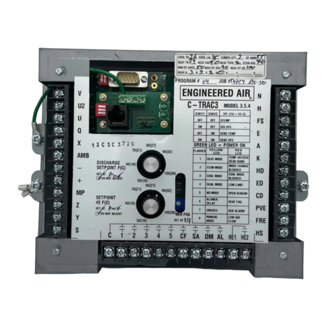
EngA DJM3 Mounting instructions

IOM‐17WWW.ENGINEEREDAIR.COMMAR99R3
USER OPERATION
MANUAL
FOR
DJM3
INDIRECT FIRED HEATING CONTROLLER
UNIT MODEL NO. _________________
UNIT SERIAL NO. _________________
SERVICED BY: ___________________
TEL. NO: ________________________
CANADIAN
HEAD OFFICE
AND FACTORY
USA
HEAD OFFICE
AND FACTORY
CANADIAN
EASTERN FACTORY
1401 HASTINGS CRES.
SE
CALGARY, ALBERTA
T2G 4C8
Ph: (403) 287-2590
Fax: 888-364-2727
32050 W. 83r
d
STREET
DESOTO, KANSAS
66018
Ph: (913) 583-3181
Fax: (913) 583-1406
1175 TWINNEY DRIVE
NEWMARKET,
ONTARIO
L3Y 5V7
Ph: (905) 898-1114
Fax: (905) 898-7244
SALES OFFICES ACROSS CANADA AND USA
Retain instructions with unit and maintain in a legible condition.
Please give model number and serial number when contacting
factory for information and/or parts.

A DJM3
IOM-17 2 of 27 Mar 99 R3
DJM3
TheDJM3hasbeencertifiedbyIntertek(ETL)forusewithEngineeredAirappliancesonly.Ithasbeen
evaluatedtoCSAC22.2No.24Temperature‐IndicatingandRegulatingEquipmentandUL873UL
StandardforSafetyTemperature‐IndicatingandRegulatingEquipment.ThisisaUserOperation
Manualandthereforenotsubjecttoevaluation.
IfanyerrorsoromissionsarenotedpleasecontactthenearestEngineeredAirTechnicalService
Department.
Toensurewarrantyishonored,onlyqualifiedpersonnelshouldbeemployedforserviceand
troubleshooting.IffurtherinformationisrequiredpleasecontactthenearestEngineeredAiroffice.
Therearetwosetsofelectricaldrawingsandunitfunctionsheetsprovidedwiththeappliance.Oneset
isinanenvelopewhichalsocontainstheOperation,InstallationandMaintenancemanual(s).This
packageisforcopying,thenshouldeitherbereturnedtotheapplianceorstoredinasafeplace.The
othersetisattachedtothecontrolpaneldoorandshouldneverberemoved.
Pleasereportanyomissionstothenationalservicemanager.
Warning:
Improperinstallation,adjustment,alteration,serviceormaintenancecancause
propertydamage,injuryordeath.Readtheinstallation,operatingand
maintenanceinstructionsthoroughlybeforeinstallingorservicingthisequipment.
Warning: Thisunitisconnectedtohighvoltages.Electricalshockordeathcouldoccurif
instructionsarenotfollowed.Thisequipmentcontainsmovingpartsthatcanstart
unexpectedly.Injuryordeathcouldoccurifinstructionsarenotfollowed.All
workshouldbeperformedbyaqualifiedtechnician.Alwaysdisconnectandlock
outpowerbeforeservicing.DONOTbypassanyinterlockorsafetyswitchesunder
anycircumstances.

A DJM3
IOM-17 3 of 27 Mar 99 R3

A DJM3
IOM-17 4 of 27 Mar 99 R3
TABLEOFCONTENTS
INTRODUCTION...............................................................................................................................................................5
CONTROLLERRATINGS.....................................................................................................................................................5
CONTROLLERDESCRIPTION..............................................................................................................................................6
TERMINALS..................................................................................................................................................................................6
DIPSWITCHES..............................................................................................................................................................................7
INDICATIONANDDIAGNOSTICLIGHTS........................................................................................................................................7
ADJUSTMENTPOTS......................................................................................................................................................................8
MULTIMETERTESTPOINTS..........................................................................................................................................................9
SYSTEMTIMINGS.........................................................................................................................................................................9
TEMPERATURECONTROL.................................................................................................................................................9
CALCULATEDSETPOINT(SPC)......................................................................................................................................................9
DISCHARGETEMPERATURESENSOR(DTEMP)..........................................................................................................................10
MODULATINGROOMRESET......................................................................................................................................................10
MultipleRoomSensors....................................................................................................................................................11
ROOMRESETAUTHORITYTABLE...............................................................................................................................................11
BMSRESET.................................................................................................................................................................................12
AMBIENTRESET(CONTINUOUSBLOWEROPERATIONONLY).................................................................................................................12
MAKE/BREAKRESETANDOVERRIDE...........................................................................................................................................13
“OR”and“V”Override(DayOperationonly)..................................................................................................................13
“X”and“Z”Override(DayandNightOperation).............................................................................................................13
OPERATION...................................................................................................................................................................14
DAY/NIGHTOPERATION...........................................................................................................................................................14
FANCONTROL............................................................................................................................................................................14
DAMPERCONTROL....................................................................................................................................................................14
BURNERCONTROL.....................................................................................................................................................................14
LOWLIMIT..................................................................................................................................................................................15
ResettingLowLimit..........................................................................................................................................................15
SERVICE.........................................................................................................................................................................15
SERVICEMODE...........................................................................................................................................................................15
BURNERSETUP..........................................................................................................................................................................15
TEMPERATURECONTROL..........................................................................................................................................................22
AIRBALANCING..........................................................................................................................................................................22
PRE‐PURGEPROBLEM................................................................................................................................................................22
INDUCEDVOLTAGEONREMOTECONTROLWIRING..................................................................................................................23
CALIBRATION.................................................................................................................................................................23
DISCHARGESENSOR........................................................................................................................................................................23
DISCHARGESETPOINTCALIBRATION...................................................................................................................................................23
ROOMSENSORCALIBRATION............................................................................................................................................................23
BMSSIGNALCALIBRATION...............................................................................................................................................................24
SENSORTABLE...........................................................................................................................................................................24
FANOPERATIONFLOWCHART........................................................................................................................................25
HEATOPERATIONFLOWCHART......................................................................................................................................26
UPGRADINGDJM3.2OR3.3TODJM3.4.........................................................................................................................26

A DJM3
IOM-17 5 of 27 Mar 99 R3
INTRODUCTION
TheDJM3isanindependentcontrollerforEngineeredAirDJstylegasfiredheatingequipment
designedtoprovidethemajorityofcontrolrequirements.TheDJM3modulatesavariablespeed
combustionblowerinconjunctionwithanmodulatinggasvalve.Thecombustionblowerspeedand
thegasvalveflowratearebothmodulatedtomaintaintherequireddischargeairtemperature.
Theinformationusedinthismanualshouldbeusedinconjunctionwiththeunitfunctionsheet(s)and
theDJ(E,S)&DGorDJXseriesInstallation,Operation,andMaintenancemanuals.
TheDJM3isdesignedtocontrolonlyEngineeredAirequipment.Variousupgradesandimprovements
havebeenmadeovertime.Alwaysincludeanysuffixlettersandnumbersfortroubleshootingand/or
replacement.
Note:Itisnecessarythatalloftheremotewiringandcontrolsbecompleteandoperationalbefore
startingtheappliance.
CONTROLLERRATINGS
Powerrequirements:24Vac,40VA.
ContactRating:120V5Ainductive
0‐10Vdcinputimpedance:2k
Environment:‐40to120°F(‐40to50°C)non‐condensing.
FuseRating:1.5GDCslow‐blow

A DJM3
IOM-17 6 of 27 Mar 99 R3
CONTROLLERDESCRIPTION
TERMINALS
TABLE1
Terminal Description
T1 Boardpowersupply.(HOT)24Vacisolated.
T2 Boardpowersupply.(NEUTRAL)24Vacisolated.
FS Fanswitch(orDaymode)enableinput(24Vac).
K Night(unoccupied)modeenableinput(24Vac).
HS Heatenableinput(24Vac).
N Grounded24Vacneutral(referencetoFS,K,HS).
DM1,DM2 Dampermotoroutputcontacts(dry).
FR,CFR Flamerelayoutputcontacts(dry).
AL Alarmoutput.
C Contactcommoninputpower(toALandSA).
SA Supplyairfanenableoutput.
CB1 Combustionblowermotorinput.
CB2 Combustionblowermotorspeedcontroloutput.
PV1,PV2 Pilotvalvedisablecontact(dry).
VFB120 Maingasvalvefeedback(SSOV)hotinputfor120Vvalves.
VFB24 Maingasvalvefeedback(SSOV)hotinputfor24Vvalves.
VN Maingasvalvefeedback(SSOV)neutralinput.
MX1,MX2 Modulatingvalveoutput.(DCvolts)
VS Legacyinput.Notused.
OS,GS,YS Combustionblowerspeedsensorinput.
Q,U Dischargeairtemperaturesensorinput.
SSPM Internal(jumpered)orexternaldischargesetpointinputs.
VXYZ Modulating(resistive)room/returnairthermostatinputs.
OR Singlestageheatthermostatinput.
+/‐ 0‐10Vdc(4‐20mA)temperatureresetinput.

A DJM3
IOM-17 7 of 27 Mar 99 R3
DIPSWITCHES
TheDJM3optionsareconfiguredbyDIPswitchselectionand/orwiringconnections.
TABLE2
DIPSW Description
1 EnableVdcormAtemperatureresetifON.
2 EnableambientresetifON.
3 Enableroom/returntemperatureresetifON.
4 Notused.
5 Servicemode(mustbeleftOFFfornormaloperation).
6 Notused.
7 ConstantcombustionairpurgemodeifON.
8 EnablelowlimitdischargetemperaturesensingifON
Note:TheDJM3willonlyacceptonetypetemperatureresetsignal.
INDICATIONANDDIAGNOSTICLIGHTS
Thereare4statuslightsontheDJM3labeled1to4.Theyoperatein4patterns:constanton,2second
flash(onfor1second,offfor1second),1secondflash(onfor½second,offfor½second)andan
irregularflash(flashestwice,thenoff,repeat).
TABLE3
LIGHT LEDON 2SECFLASH 1SECFLASH INTFLASH
1 LLLOCKOUT LLBYPASS DSENOPEN ‐‐‐‐‐‐‐‐‐‐
2 PREPURGE PPPROBLEM ‐‐‐‐‐‐‐‐‐‐ ‐‐‐‐‐‐‐‐‐‐
3 HEATCALL HTSWOPEN ‐‐‐‐‐‐‐‐‐‐ SERVICEMODE
4 IGNENABLE ‐‐‐‐‐‐‐‐‐‐ FLAMEFAIL ‐‐‐‐‐‐‐‐‐‐
1 ON
Theappliancehasbeenshutdownduetolowlimitfailureandlockout.
(dischargetemperaturebelow4°C(40°F))Resetwiththeserviceswitch.
Normaloperatingstatus:OFF.
1 2SEC
Unithaslowdischargetemperatureandistimingout.Ifthetemperaturedoes
notrecovertoabove4°C(40°F)itwillshutdownandlockout.
Normaloperatingstatus:OFF,orwaitingforthedischargetemperaturetorise
above4°C(40°F).
1 1SEC
Thedischargesensorcircuitisopen(sensorrangemustbebetween880and
4000Ω).
Normaloperatingstatus:OFF.
2 ON
Thecombustionblowerispurgingtheexchangerasapreliminarytoignition.
Normaloperatingstatus:EITHERONorOFF.
2 2SEC
PrePurgeproblem.TheDJM3isnotreceivingacorrectsignalfromthehall
effecttachometersensor,intoterminalsYS,OS,GS.
Normaloperatingstatus:OFF.

A DJM3
IOM-17 8 of 27 Mar 99 R3
3 ON
Thedischargesensorisbelowcalculatedsetpoint(SPC)andtheDJM3has
initiatedtheheatingsequence.
Normaloperatingstatus:ONforheating.
3 2SEC
Thereisacallforheating,howevertheheatinghasbeendisabledfromno
inputintoterminalHS(24Vac).
Normaloperatingstatus:OFF.
3 INT
FLASH
Unitisinservicemode,allowingthetechniciantomanuallysettheheating
fromlowtohighfirewiththeservicepot.
Normaloperatingstatus:OFF.
4 ON
FRandCFRcontactshaveclosed,enablingtheignitioncontroltofirethe
burner.
Normaloperatingstatus:ONforheating.
4 1SEC
Burnerignitionwasunsuccessful.TheDJM3didnotreceiveamaingasvalve
(SSOV)feedbacksignalintoterminalsVFB24orVFB120.
Normaloperatingstatus:OFF.
ADJUSTMENTPOTS
Thereareanumberofsettingandcalibrationpotentiometers(POT’s)locatedonthefrontofthe
DJM3.Modificationstotheseshouldonlybedonebyexperiencedandqualifiedpersonnel.
TABLE4
POT Description
DSENCAL Dischargesensorcalibration.
DISSPCAL Dischargesetpointcalibration.
BMSCAL BMS(0‐10Vdcor4‐20mA)resetcalibration.
ROOMCAL Roomsensorcalibration.
SERVICE Servicemodepot.
RESETRATIO Temperatureresetrangeadjustment.
LOWFIRE* LowfirespeedRPMadjustmentpot(nearterminalPV1).
CURVEMATCHING* ValvecurvematchingRPMadjustmentpot(nearterminalCS).
SETPOINT Ifused,theon‐boarddischargesetpointdial.
*Thesepotsshouldonlybeadjustedwhenusedwithacombustionanalyzer.

A DJM3
IOM-17 9 of 27 Mar 99 R3
MULTIMETERTESTPOINTS
TheDJM3hasreadoutterminalsformeasuringthedischargesensortemperatureandthecalculated
dischargesetpoint.These3testpointsarelocatedneartheMandQterminals.
MeasurementsaremadeusingaVdcmultimeterusingascaleof1Vdc=10°C.Forexample,areading
of2.1Vdc=21°C(or70°F).RefertothetablebelowforCelsiustoFahrenheitconversion.
TABLE5
VoltageReading(Vdc) °C °F
1.0 10 50
1.5 15 59
2.0 20 68
2.5 25 77
3.0 30 86
3.5 35 95
4.0 40 104
SYSTEMTIMINGS
Thetimeslistedaregeneral,andmaybeaffectedbyexternaltimedelaydevices.
TABLE6
Pre‐purge 45seconds
Postpurge 4minutes(daymode)1minute(nightmode)
Fandelay 30seconds
Warmuptime 30seconds
Cooldowntime 60seconds
Lowlimitbypass 5minutes
FlameFailure 90seconds
TEMPERATURECONTROL
CALCULATEDSETPOINT(SPC)
TheDJM3isdesignedtobeadischargeairtemperaturecontrol.Thebasedischargeairtemperature
setpointistypicallysetfromthecontrolpotlocatedonthefaceoftheDJM3.Thebasedischargeair
temperatureisnormallymodifiedfromaremotesignaltomaintainthedesiredtemperatureofthe
suppliedspace.Thisiscalledreset.TheDJM3dischargesetpointcanberesetfromavarietyofsources
suchasambientairtemperature,modulatingorstagedroomthermostats,returnairtemperature,ora
BMSsignal(0‐10Vdcor4‐20mA).
Withoutanytemperatureresetmethodthebasesetpoint(eitherfacemountedorremotemounted)is
thecalculatedsetpointthattheDJM3willattempttomaintainthedischargetemperatureat.
SetpointCalculation(SPC)=DischargeSetpoint+Reset

A DJM3
IOM-17 10 of 27 Mar 99 R3
TheDJM3isdesignedtouseeitherofthefollowingasasetpoint:
ThesetpointmountedonthefaceoftheDJM3(rangeof50‐95°F(10‐35°C)).IftheDJM3face
mountedset‐pointisused,terminals“SPandS”mustbejumpered;or
TheJohnsonControlsTE6100‐960set‐point(rangeof50‐85°F(10‐29°C)).IftheTE6100‐960isused
asaset‐point,“StoSP”isnotjumperedandtheTE6100mustbewired:
TABLE7
TE6100Wires DJM3Terminals
Violet(notused) ‐
Red(notused) ‐
Grey WiredtoterminalU
Blue WiredtoterminalM
Orange WiredtoterminalS
DISCHARGETEMPERATURESENSOR(DTEMP)
TheDJM3usesthedischargesensorforbothtemperaturecontrolandlowlimit.Becauseofthis,the
DJM3willnotoperatewithafaultydischargesensor.Ifthedischargesensorresistanceisgreaterthan
4000‐ohmsorlessthan880‐ohms,theunitwilllockouteitheronlowlimitorbadtemperaturesensor.
MODULATINGROOMRESET(continuousbloweroperationonly)
DIPswitch3mustbe"on".ThisoptionalsorequiresaTE6100wired:
TABLE8
TE6100Wires DJM3Terminals
Red(notused) ‐
GREY WiredtoterminalV
VIOLET WiredtoterminalX
ORANGE WiredtoterminalY
BLUE WiredtoterminalZ
IfDIPswitch3isonandtheTE6100isnotwiredtothecorrectDJM3terminals,theDJM3willresetthe
dischargetemperaturedownasitthinksthattheroomsensorisverywarm.Theroomtemperature
requirementscanincreaseordecrease(reset)thecalculateddischargeairset‐point.
Note:Ifroomresetcalling,the“calculated”dischargetemperaturesetpointwillvaryfromthesetting
of“master”setpoint.
Theroom‐resetfeatureisactivatedbyDIPswitch3.
RoomsensorcalibrationpotisRoomCalPot.
Roomresetbandis3°F(fixed).
The“roomresetband”meansaroomtemperatureerrorofjust3°Fwillresultinamaximumresetof
thedischargeairsetpoint.Theactualamountreset(indegrees)variesasperboththesettingofPot
ResetRatioandthedischargesetpoint.Thecalculateddischargeairsetpoint(dialsetting+reset)is
limitedbetween48and120°F.

A DJM3
IOM-17 11 of 27 Mar 99 R3
TodeterminetheamountofresetavailablerefertoTable9.
EXAMPLE:DJM3setpoint70°F;pot#5setat3;roomthermostatset75°F.
Ifroomthermostatsensorisat75°F‐noreset,dischargeat70°F.
Ifroomsensoris3°Fcold(72°F),dischargeisresetupfullamountofitsauthority(+20)to90°F.
Ifroomthermostatwasat73°Fthenoftheresetwouldbeused(*20isapprox.14°F),
addedontotheset‐pointof70°Fgivingdischargeof84°F.
Ifroomsensoris3°Fhot(78°F)fullresetdownwilllowerthedischarge13°(57°Fdischarge).
MultipleRoomSensors
FoursensorscanbewiredtogiveanaveragereadingofroomtemperaturestotheDJM3control.They
mustbewiredinaseries/parallelarrangement.Refertomainorfieldelectricaldiagramfor
appropriatewiring.
ROOMRESETAUTHORITYTABLE
TABLE9
Discharge
Set‐Point
Reset
Ratio
Pot
Maximum
Temp.°C
Minimum
Temp.°C
Reset
Band
Width
°C
Maximum
Temp.°F
Minimum
Temp.°F
Reset
Band
Width
°F
15.5°C
60°F
1 25(+9.5) 12(‐3.5) 13 77(+17) 54(‐6) 23
2 26(+10.5) 11.5(‐4) 14.5 79(+19) 53(‐7) 26
3 28(+12.5) 10.5(‐5) 17.5 82(+22) 51(‐9) 31
4 33(+17.5) 9(‐6.5) 24 91(+31) 48(‐12) 43
5 38(+22.5) 9(‐6.5) 29 100(+40) 48(‐12) 52
21°C
70°F
1 29(+8) 16(‐5) 13 84(+14) 61(‐9) 23
2 30(+9) 15(‐6) 15 86(+16) 59(‐11) 27
3 32(+11) 14(‐7) 18 90(+20) 57(‐13) 33
4 37(+16) 11(‐10) 26 99(+29) 52(‐18) 47
5 40.5(+19) 9(‐12) 31.5 105(+35) 48(‐22) 57
27°C
80°F
1 33(+6) 21(‐6) 12 91(+11) 70(‐10) 21
2 34(+7) 19(‐8) 15 93(+13) 66(‐14) 27
3 35.5(+8) 18(‐9) 17.5 96(+16) 64(‐16) 32
4 39(+12) 15(‐12) 24 103(+23) 59(‐21) 44
5 44(+17) 11(‐16) 33 111(+31) 52(‐28) 59
32°C
90°F
1 38(+6) 25(‐7) 13 100(+10) 77(‐13) 23
2 38(+6) 23(‐9) 15 101(+11) 74(‐16) 27
3 40(+8) 22(‐10) 18 104(+14) 72(‐18) 32
4 44(+12) 18(‐14) 26 111(+21) 64(‐26) 47
5 47(+15) 13(‐19) 34 116(+26) 56(‐34) 60
NOTE: Theabovetableisnotlinearandresetupanddownisequalataset‐pointofabout82°F

A DJM3
IOM-17 12 of 27 Mar 99 R3
BMSRESET(continuousbloweroperationonly)
DIPswitchonemustbeontoactivateBMSreset.Thisoptionrequiresananalogvoltageorcurrent
signaltobewiredtotheopticallyisolated+and‐terminals.Theanaloginputsignalproportionally
increasesthecalculateddischargeairset‐point.Thecalculateddischargeset‐pointequalsthedial
dischargeset‐pointplustheinputsignalmultipliedbyaresetratiofactor.
Themaximumamountofresetisadjustablefrom15°F(8°C)to60°F(33°C).Themaximumdischarge
temperature(dialset‐pointplusreset)islimitedto120°F(49°C).TheBMSresetoptionisactivatedby
DIPswitch1.
Note: Asstandard,theDJM3isdesignedtooperatewith4‐20mAor2‐10Vdcintoa500‐ohminput
impedance.SomeBMSdevicesmaynothaveenoughpower(Volt‐Amps)toprovideafull10
VDCwhenconnectedtoa500‐ohmload.Theinputresistanceforthisoperationcanbe
increasedto1500ohmsbycuttingresistorR43.Tocutthisresistoryoumustturntheboard
over.Itislocatedonthebackofthelargerboard,justbelowtheDIPswitchblockandbeside
PotResetRatio.Thisisa1‐watt,680‐ohmresistorcoloursblue,grey,brown,gold.
BMSresetisnottrulylinear.Resetwillusuallybeginatabout4volts.Following,isanexampleofreset
fromoneapplicationthatgivesa13°Cor24°Freset.
CALCULATEDSETPOINTFROMBMSRESETAPPLIEDTO+AND–
TABLE10
Current
Reset
Voltage
Reset
CalculatedSetpoint
mA Vdc °C °F
‐ 0 13 55
3 3 13.5 56
5 4 14.5 58
12 6 16 61
‐ 7 18 65
16 8 20 68
‐ 9 23 75
20 10 26 79
AMBIENTRESET(continuousbloweroperationonly)
ThisoptionrequiresDIPswitch2tobeonandanambientsensor(JohnsonControlsTE6000‐960)
wiredtoterminalsXandZ.Thedischargeairset‐pointwillberesetupwardsbasedontheambient
temperature.Ambienttemperaturesbelow70°F(21°C)willgraduallyincreasethecalculateddischarge
airset‐point.Themaximumincreaseinthedischargetemperaturewillbereachedwhentheambient
fallsto20°F(‐7°C).TheamountofresetisdependentonthepositionofResetRatioPotandthe
dischargeset‐pointassetonthedial.
(Thedischargeset‐pointwillberesetbelowmasterset‐pointifambientisabove70°F(21°C).Inmost
caseswhentheoutsideambientisabove70°F(21°C),theheatwillbeoff.)

A DJM3
IOM-17 13 of 27 Mar 99 R3
Itispossibletoobtainanextendedtemperaturerangebyplacinga120‐ohmresistorinserieswiththe
ambienttemperaturesensor.
Note: Withthisresistorthedischargetemperaturewillbeatitsmaximumwhenambientisat‐15°F.
Withthisresistor,thecalculateddischargeairset‐pointequalsthedialset‐pointat35°F
(differentfromabove).Above40°Fthecalculateddischargeairtemperaturewillbebelowthe
dialset‐point.
TABLE11
ResetRatioPot
Setting
ResetAmount°F
(noresistor)
ResetAmount°F
(witha120ohmresistorinseries)
1 10 18
2 11 20
3 13 24
4 16 30
5 21 37
MAKE/BREAKRESETandOVERRIDE
“OR”and“V”Override(DayOperationonly)
ToactivatethisfeatureDIPswitch3mustbeoff.Ifathermostatorcontactisclosedacrossterminals
“OR”and“V”,thedischargetemperatureissetat120°F(49°C).Whenthermostatorcontactisopen,
thedischargetemperatureissetatthedialsetpointplusanyotherresetsbeingused.
“X”and“Z”Override(DayandNightOperation)
ToactivatethisfeatureDIPswitch3mustbeon.Duringdayoperation,ifathermostatorcontactis
closedacrossterminals“X”and“Z”,thedischargetemperatureissetatthedialsetpointplusthe
maximumamountofresetupwards.Whenthethermostatorcontactisopenacrossterminals“X”and
“Z”,thedischargetemperatureissetatthedialsetpointlessthemaximumamountofreset
downwards.
DuringNightoperation,ifathermostatorcontactisclosedacrossterminals“X”and“Z”,thedischarge
temperatureissetat120°F(49°C).Whenthethermostatorcontactisopenacrossterminals“X”and
“Z”,heatisoff.

A DJM3
IOM-17 14 of 27 Mar 99 R3
OPERATION
DAY/NIGHTOPERATION
TheDJM3supportsavarietyoffan,damper,andtemperaturecontroloperatingschemes.Theexact
operationdependsonthestatusofterminals“FS,HS”,and“K”.Nightoperationisnotsuitablefor
100%make‐upairapplications,duetotheequipmenthavingtoopenoutsideairdampersandheat
outsideair.TooperateinNightmode,aroomthermostatormake/breakresetmustbeused.
TABLE12
TerminalStatus Blower
Operation
Damper
Operation ControlSource Control
Mode
HS FS K
XXX
XXX
Off
On
Off
Off
Off
Constant
Off
Powered
N/A
Discharge/Room/BMS
Off
Day
Off
On
On
XXX
Off
On
On
On
On
Off
Intermittent
Constant
Off
Off
Off
N/A
Room
Dischargew/Room
Reset
Off
Night
Night
XXX=Switch(SW.)canbe"ON"or"OFF"
FANCONTROL
Indaymode,thesupplyairfanshouldruncontinuously(unlessjuststartingthemorningwarm‐upor
trippedonlowlimit.).Forsupplyfanoperation,thedischargesensormustbeoperatingcorrectlyasit
isalsousedasthelowlimitsensor.Ifthedischargesensorresistanceistoohigh(oropencircuit),the
DJM3perceivesalowlimitfaultandlocksoffDJM3.
DAMPERCONTROL
Theinletdamperactuator(s)isenabledthroughoutputterminalDM2.TheDJM3hasadelayedsupply
blowerstarttoallowtimeforthedamperstoopen.
BURNERCONTROL
Burnerisenabledwhenavalidheatcallismadeandterminal“HS”ispowered.TheDJM3willentera
heatexchangerpurgecycle.Whenthepurgecycleiscomplete,theDJM3willruncombustionblower
atlight‐offspeedandenabletheignitioncontroltostartthepilot.Whentheignitioncontrolproves
pilotlight‐offitwillenablethemaingasvalve.OncethemainflameisestablishedandtheDJM3
receivesafeedbacksignaltoterminalsVFB24orVFB120andVNthecontrolwillmodulatethegas
valveandcombustionblowertosatisfytheheatcall.IftheDJM3doesnotreceivethefeedbacksignal
thealarmcontact,terminal“AL”,willbeactivated.
WhenheatcallissatisfiedtheDJM3willcycleofftheburner.Thecombustionblowerwillcontinueto
runforseveralminutesafterheatcallisopentomaintainpurgeandcoolofftheburnerandheat
exchanger.

A DJM3
IOM-17 15 of 27 Mar 99 R3
LOWLIMIT
Thelowlimitsetpointisfixedat40°F.Therearetwolowlimitbypasstimers,start‐upandanti‐noise.
Thestart‐upautobypasslowlimittimerisstartedeverytimeterminal“K”,“SA”or“FS”energized
statuschanges(on/off).Thestart‐uptimerwillbypassthelowlimitfor5minutes.Afterthe5minute
startupbypass,a30‐secondanti‐noiselowlimitbypasstimerisstartedeverytimealowlimit
conditionisdetected.Thistimerisdesignedtopreventnuisancetripscausedbyanyelectricalnoise
pickedupbythedischargesensor.Ifthelowlimitconditionexistsformorethan30seconds,alow
limitlockoutwilloccur.ThiswillactivatethealarmcontactontheDJM3,terminal“AL”.
ResettingLowLimit
Toresetthelowlimit,cyclepowertotheDJM3controlterminals"T1"and/or"T2";orinterruptpower
toterminals"FS,HS,andK"allatthesametime.
SERVICE
SERVICEMODE
PlacingtheDJM3intoservicemodeallowsfordirectcontroloftheburnerfiringrate.DIPswitch5will
activateservicemodeandenabletheheatimmediately.TheservicePOT,locatedtotherightofthe
setpointdial,willmanuallysettheburnertoanyfiringrate.Wheninservicemode,thesupplyairfan
mayneedtobeactivatedmanually.
Note:DONOTleaveDJM3inservicemode,burnerwillnotcycleoff.Servicemodeshouldonlybeused
forcombustionset‐upandoperationalchecks.
BURNERSETUP
ServicePot
Thispotisdesignedtoallowaservicetechniciantomanuallysettheburnertoanyfiringratehe
chooses.Iftheserviceswitch(dipswitch5)isonandtheblowerswitch(terminalFS)ispowered,the
burnerfiringrateiscontrolledbytheServicePot.TheServicePotislocatedclosetothe“+"terminal
andabovethedipswitches.Rotatingthispotwillallowthefiringratetobesetatanyratebetweenlow
andhighfire.
LowFirePot
ThelowfirepotislocatedbelowthePV1terminal.Thelowfirepotisusedtoadjustthecombustionair
atlowfire.Thelowfirespeedisadjustablefrom1150to1400RPM(highturndown)or1800to2000
(standardburner).Thelowfirepotistobeadjustedbyaqualifiedservicetechnicianonly.
CurveMatchingPot
ThecurvematchingpotislocatedbelowtheCSterminal.TheDJM3canbeusedwithseveraldifferent
Maxitrolvalves.Eachofthesevalveshasaslightlydifferentopeningcurve.TheCurveMatchingPotis
tobeadjustedbyaqualifiedservicetechnicianonly.

A DJM3
IOM-17 16 of 27 Mar 99 R3
BurnerSelection
TheDJM3isdesignedtooperatewithboththestandard(roundburnerplate)andhighturndown
(rectangular)burners.TheselectionismadebycuttingajumperwireR100whichislocatedonthe
smallboard.(TheDJM3mustbeturnedovertoaccessthejumperwire.)
NOTE: JumperwireR100iscutonlyforthehighturndownburneroperation.Caution–donotcut
resistorR100onthelargeboard.
NOTE: Donotadjustanyotherpotslocatedonthesmallboard,whicharenotaccessiblefromthe
frontoftheDJM3
CombustionSetUp
Whenmeasuringcombustiongases,ensureprobeofanalyserinsertsfullyintotheflueconnectionto
theheatexchanger.Measuringattheflueoutletmaybeadilutedreadingduetoairmixingintothe
flue.
NOTE: Ifcombustionisnotsetcorrectlyitcanresultimproperburningwhichmayproduce
productsofcombustionthatsmell,carbonandoranexcessiveamountofwaterintheflue.
Careshouldbetakentosetburnersupproperly.Notethattemperatureoftheairandfuel
mayhaveagreataffectonthesetupselected.Ifboththecombustionairandthefuelare
ataconstanttemperaturethroughouttheheatingseason,oncecombustionissetitshould
remainsimilarthroughtheseason.
HighTurndown(Rectangular)Burner
MosthighturndownDJunitswillemployonofthefollowingMaxitrolmodulatingDCvoltgasvalves.
Series20 420,M520,M620.Thesevalvesdonothavehighfireregulators.Highfirepressureis
setupattheapplianceregulator.
Series50 550,M650,ES350.Thesevalvesdonothavehighfireregulators.Highfirepressureis
setupattheapplianceregulator
ES345D‐L Thisvalvehasabuiltinhighfireregulator.TypicallyusedonDJ140models.
Theabovevalvesdifferfromeachotherinsize,configuration,BTUcapacity,physicallayout,andlow
firesetup.
Check the equipment to verify what type of modulating gas valve you have to ensure the correct
combustionsetupmethodisused.

A DJM3
IOM-17 17 of 27 Mar 99 R3
HighFireSetUp
1. Turnontheserviceswitch(dipswitch5).
2. SettheServicePottohighfire.Adjustthehighfireinputtothecorrectclockedrate.Adjust
combustionairsliderorinletdamperuntilthehighfireO2readingisbetween3.5and4.2%.
LowFireSetUp
Ensurethatthereisaluminiumtubingconnectedfromthetopofthemodulatinggasvalvevent
connectiontotheburnerbox.Thisistoguaranteethatthevaryingburnerboxairpressureallowsthe
propergasflowratethroughthemodulatinggasvalve.Alsoensurethatthesmallventholeunderthe
ovalshapedcoverissealedoffwithsiliconeorTremcotape.Whendoingcombustionanalysisitis
importantthatthetopofthevalvebesealedbyeitherreinstallingthecapaftereachadjustment,or
placingyourfingerfullyoverthetoptosealtheopentoponthevalve.Thereasonforthisrequirement
isthatthevalveis“toploaded”whichmeansthatthevalveishavingpressurefromthecombustionfan
addedtothetopofthevalve’sdiaphragmthusincreasingthegasflowthroughthevalve,especiallyat
higherflow.
Series20/M420,M520andM620(HighTurndownBurner)
Thesevalveshave2lowfireadjustmentsthefollowingprocedureshouldbefollowedcarefully.
Oncethehighfirepressureandcombustionhasbeensetup,turntheServicePotfullycounter‐
clockwisetoachievelowfire.AdjusttheLowFirePotuntilthelowfirespeedonthecombustionfan
motoris1250RPM±10RPM(20.8Hz)for10:1setupor1195RPM±5(19.91Hz)for15:1turndown.
AtthispointtheDCvoltagereadingatthemodulatinggasvalveterminalsshouldbe0VDC.
UnderthecoverontheMaxitrolseries20valveisanadjustmentscrew(brassorsilver)thathasalock
ringwhichusesaspecialtool(twoverysmallholes)toloosenit.
1. Thelockringneedstobeloosenedfirst.TurnitfullyCCW(up)nowturntheslotscrewin
thecentreofthelockring(springactivatedlowfireadjustment)fullCCW(up).
Caution:Donotovertorquethisscrewatthetoporbottomofitsadjustmentoritwill
breakthe“c‐clip”insidethevalve,thusallowingthespringtoridefree.
2. AdjustthelowfirebypassscrewatthebottomsideofthevalvebodyuntiltheO2readingis
between16.0%to16.5%.(16.5to17.5%oxygenfor15:1turndown.)Atthesesettingsthe
turndownwillbeverycloseto10:1.ThemaximumCOatlowfireis80PPM.
3. AdjusttheServicePotupveryslowlyuntiltheDCvoltsatthe modulating gas valve
terminalsareabout2.25VDC.Ifthevoltagerisesover2.25VDCwhileadjustingthemanual
pot,turnitdownandstartagainfromlessthan1.5VDCuntil2.25VDCisreached.
4. ChecktheO2readingagainatthispoint.IftheO2hasincreased,adjustthespringactivated
lowfireadjustmentontopofthevalveuntiltheO2readingissameasthelowfirereading
at0VDC.

A DJM3
IOM-17 18 of 27 Mar 99 R3
5. CurveMatchingProcedure
TurnServicePottohighfire(approximately3450RPMor57.5Hz)for1minute.Adjustthe
ServicePotdownveryslowlyuntilthecombustionmotorspeedisabout3060RPM(51Hz).
Ifthepotisadjustedbelow51Hzreturntohighfireandattempttolowerwithoutpassing
51Hz.Lettheburnerstabilizefor2minutes,thenre‐checkO2reading.IfO2hasdroppedto
lessthantheoriginalhighfireO2 reading, adjust the Curve Matching pot. Adjusting CCW
increasestheO2readingbyreducingthevoltagetotheMaxitrolmodulatinggasvalve.The
CurveMatchingpotonlychangesthevoltagetothegasvalve;itdoesnotaffectfanspeed.
IfthecurvematchingpotisadjustedtothefullyCCWpositionandtheO2readingisstillnot
within 10% of the original high fire O2 reading, add a 180‐ohm 2 watt resistor across the
modulatinggasvalveterminals;repeatabovetestuntilpropercurvematchingisachieved.
(A150‐ohm,2‐wattresistormayhavetobeusedifO2levelstilldoesnotrisetowithin10%
oforiginalhighfireO2reading.)
Switch burner to low fire again and re‐check low fire, both at 0 VDC and 2.25 VDC. (An
additionofaresistorabovemayhavechangedthelowfiresetting,ifitwasneeded.)
Lockthelockingringonthespringactivatedlowfireadjustmentscrew(fromstep1).Failure
tolockitmaycausethescrewtovibratelooseallowinglowfire gaspressuretoincrease.
Thiscancreatesootingofburnerpartsandtheheatexchanger.Ifthelockingringismissing,
droponedropofLoctitethreadlockerontothebrassscrewthreads.
Series50/M550,M650ANDES350(HighTurndownBurner)
Thesevalveshaveonly1lowfireadjustment(springactivatedlowfire).
1. Thecombustionsetupissimilartotheaboveexceptthereisnolowfirebypassadjustment
onthebottomofthesevalves.Thereforesimplysetuplowfirebyturningthemanualfiring
PotResetRatiotothelowfireposition‐1250RPM10RPM20.8Hz.(15:1turndownsetat
1195RPM,19.91Hz.)Voltagetotheseries50valveshouldbenear0voltsDC.Adjustthe
springactivatedlowfireadjustmentatthetopofthemodulatinggasvalve(smallscrew)
untilanO2readingof16.8%to17.5%isachieved.
2. Lockthelowfireadjustmentscrewasdescribedinpoint7aboveandthenadjustthecurve
matchingpotasinpoint5above.
TypeES345D‐L(HighTurndownBurner)
Asthisvalvehas2lowfireadjustmentsthefollowingprocedureshouldbeapplied.
1. BringtheunittolowfireusingtheservicefiringpotfullyCCW.AdjustPotLowFireuntilthe
combustionfanisturning1250RPM10RPM(20.8Hz).(15:1turndownis1195RPM,19.91
Hz.)VoltagetotheESvalveshouldbenear0voltsDC.Thelowfirebypassadjustmenton
thisvalveisunderthetopcoveronthelargeportandtheadjustmentinsideitismarked:
IncreaseDecrease
Afterremovingthecover,loosenthelockingscrewfirstbefore making adjustment. This
shouldbedoneat0VDCtothemodulatinggasvalveterminalsandthespringactivatedlow
firebrassscrewturnedfullyCCWandthelockingringloosenedoff.

A DJM3
IOM-17 19 of 27 Mar 99 R3
2. Bringvoltagetogasvalveat2.25VDCandadjustthespringactivatedlowfireadjustment
located in the head with the electric modulator (smaller screw under cap) to achieve the
sameO2readingastheoneachievedat0VDC(16.8%to17.5%O2).Afterthisiscomplete
thenadjusttheCurveMatchingpotasdescribedinpoint5above.
PilotSetUp(HighTurndownBurner)
1. Onhighturndownunits,ensureairtubetopilotisfreeofdebrisandblockagesandthenset
pilotpressureto3.5"WC.
2. Pilotsetupisnotascriticalonthehighturndownburnerasthereisnotasmuchheatonit
asontheregularburner.
Standard(Round)Burner
MoststandardturndownDJunitswillemployoneofthefollowingMaxitrolmodulatingDCvoltgas
valves.
Series20M520,M620 Thesevalvesdonothavehighfireregulators.Highfire
pressureissetupattheapplianceregulator.Ifusedonthe
standardburner,thelowfireadjustmentlocatedonthe
bottomsideofthevalveistobeadjustedfullyclockwise
(nobypass).
Series50M550,M650,ES350 Thesevalvesdonothavehighfireregulators.Highfire
pressureissetupattheapplianceregulator.Thisseriesof
valvehasbeenreplacedwiththeM520/620series.
ES345D‐LThisvalvehasabuiltinhighfireregulator.
HighFireSetUp
1. Turnontheserviceswitch(dipswitch5).
2. SetmanualfiringPotHiService(locatednexttothe+terminal)tohighfire.Adjustthehigh
fireinputtothecorrectclockedrate.Adjustthecombustionairsliderorinletdamperuntil
thehighfireO2readingisbetween3.5and4.2%.
LowFireSetUp
Lowfireblowerinputis40%ofhighfireblowerinput.
Thelowfireproceduresetupissimilartothatforthehighturndownburnersnotedabove.The
differenceisthemaximumallowableCOatlowfireis200PPM.ThelowfireO2readingshould
bebetween10.9%to11.3%.Thecombustionsliderisdifferentthanthehighturndownslider.It
isaplatethatslidesbetweenthebloweroutletandtheburnerbox.ThelowfireRPMis
adjustedusingLowFirePotto185010RPM(30.5Hz).
Aftersettingupthelowfire,adjustthecurvematchingpotasdescribedinpoint5above.

A DJM3
IOM-17 20 of 27 Mar 99 R3
PilotSetUp(StandardBurners)
Donotsetuppilotuntilyouareconfidenttheburnerisoperatingwithcorrectair/fuelmixture.
Ensurethepilottubeisfreeofdebrisand blockages.Onstandardroundburners,setpilotas
perthefollowingprocedure.
1. Installa10,000‐ohmresistorinserieswiththeflame
rodcircuit.
2. ConnectaDCvoltmeteracrosstheresistor.
3. Thereadingwillbeinmillivoltsifyourmeterdoes
notautoscale.
4. Connectamanometertothepilotline.
5. Runtheburneronmainflameforafewminutesto
havetheburnerplatewarm.
6. Leavethepilotonbutturnthemaingasoff.Youwill
havetojumpertheDJM3terminalsPV1andPV2to
dothisandremovethewirefromterminalVFB120orVFB24(dependingonvalvevoltage).
7. Aslowpilotgaspressurecandamagetheceramics,reducethepilotgaspressureto2.5
inchesandimmediatelyreturnittoahigherpressure.Thisistoensurethepilotgasregular
respondsproperly.
8. Adjustthepilotvalveregulatortoapressureinexcessof4.5inchespressure.
9. Slowlyreducethepilotgaspressurewhilewatchingboththepressureandthevoltmeter.
Themillivoltreadingshouldbeincreasing.Atthepointwhereitbeginstofallyoushould
stopreducingpressureandreturntothehighspot.
NOTE: Thefallinpressurecouldonlybeassmallasacoupleofmillivolts.Thispointshouldbe
between4.5and2.5inchespilotpressure.
NOTE: Somesmallerburners(DJ40250,000BTUHandsmaller),mayneedtohaveascrewplaced
throughthepilotairtubetoreducetheamountofairtothepilot.
10. Thisreadingisusedtodeterminetheadjustmentthatwillusuallygivethebestpilotlighting
andprovingstrength.However,caremustbetakentonotadjustthereadingforpilotgas
pressurebelow2.5incheswatercolumnpressureoryouwillbreakthepilotceramics.
11. Next,visuallyobservethepilotflame.Itshouldbevisibleataminimumof3oftheholes
aroundthepilot.Ifthepilotcannotbeseenthenitislikelyburningtoodeepintothepilot
box.Ifthisisoccurringcheckthatthegasketonthepilotassemblyisformingatightseal.
Alsoensurethattheburnerislocatedinthecenteroftheburnertube.Ifitismountedtoo
lowthentoomuchaircanflowoverthetopoftheburnerandaffectthepilot.
NOTE:Aftersetupiscompletemakesuretoturnoffdipswitch5.
Ignition
Control
10,000ohms
MVmeter
OK
Toolargeagap.Raise
burnerplateupto
centre.
Table of contents
Other EngA Controllers manuals
Popular Controllers manuals by other brands

West Control Solutions
West Control Solutions ProVU4 user guide
National Instruments
National Instruments NI cRIO-905x Series user manual

ITC
ITC VISIONS 3000 user manual
Koganei
Koganei FRZB instruction manual
VAT
VAT 075 Series Installation, operating, & maintenance instructions
Siemens
Siemens REV200 Series manual
