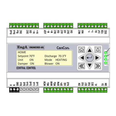
EngA ENGINEERED AIR DJM2.4 User manual

A
IOM-16 Oct 00 R2
INSTALLATION, OPERATION
AND MAINTENANCE MANUAL
FOR
DJM2.4
INDIRECT FIRED HEATING CONTROLLER
UNIT MODEL NO. _________________
UNIT SERIAL NO. _________________
SERVICED BY: ___________________
TEL. NO: ________________________
CANADIAN
HEAD OFFICE
AND FACTORY
USA
HEAD OFFICE
AND FACTORY
CANADIAN
EASTERN FACTORY
1401 HASTINGS CRES. SE
CALGARY, ALBERTA
T2G 4C8
Ph: (403) 287-4774
Fx: 888-364-2727
32050 W. 83rd STREET
DESOTO, KANSAS
66018
Ph: (913) 583-3181
Fx: (913) 583-1406
1175 TWINNEY DRIVE
NEWMARKET, ONTARIO
L3Y 5V7
Ph: (905) 898-1114
Fx: (905) 898-7244
SALES OFFICES ACROSS CANADA AND USA
Retain instructions with unit and maintain in a legible condition.
Please give model number and serial number when contacting
Engineered Air for information and/or parts.
www.engineeredair.com

A
IOM-16 Oct 00 R2
DJM2.4
If any errors or omissions are noted in this manual please contact Engineered Air –Calgary Service
at (403) 287-2590 or Fax (403) 287-4799 or email service@engineeredair.com.
To ensure warranty is honored, only a qualified HVAC service person, who has received training on
the DJM2.4, should be employed for service and troubleshooting. If further information is required
please contact the nearest Engineered Air office.
Under no conditions (except for temporary copying) should the unit function description be
removed from the unit. There are two copies provided with the unit. One is in an envelope for
copying, then return it to the unit or store in a safe place. The other is attached to the control panel
door and should never be removed. If a copy of the function for a particular unit is needed, contact
Engineered Air with the unit serial number and DJM2 model number (ex model DJM-2.4).
Warning:
m
c
This unit is connected to high voltages. Electrical shock or death could occur if
instructions are not followed. This equipment contains moving parts that may start
unexpectedly. All work should be performed by a qualified technician. Always
disconnect and lock out power before servicing. DO NOT bypass any interlock or
safety switches under any circumstances.

DJM2.4 MANUAL
3 Oct 00 R2

DJM2.4 MANUAL
4 Oct 00 R2
TABLE OF CONTENTS
TEMPERATURE CONVERSIONS .......................................................................................................................................5
I. APPLICATION...........................................................................................................................................................5
II. SERVICE ....................................................................................................................................................................5
III. GENERAL...................................................................................................................................................................6
IV. WIRING .....................................................................................................................................................................7
V. SYSTEM TIMINGS .....................................................................................................................................................7
VI. POTS..........................................................................................................................................................................7
VII. HIGH FIRE OVERRIDE .........................................................................................................................................8
VIII. STATUS LIGHTS...................................................................................................................................................8
IX. BASIC BURNER OPERATION.................................................................................................................................10
X. TEMPERATURE CONTROL –GENERAL OVERVIEW.....................................................................................................11
XI. BMS CONTROL .......................................................................................................................................................13
XII. BMS CALIBRATION AND SET UP ......................................................................................................................13
XIII. DISCHARGE SENSOR READOUTS, CALIBRATION, ETC...................................................................................14
XIV. BURNER SET UP.................................................................................................................................................16
XV. SPECIAL SERVICE NOTES..................................................................................................................................24
XVI. SET UP WHEN INSTALLING A DJM2.4 IN FIELD..............................................................................................33
XVIII. MISCELLANEOUS NOTES..............................................................................................................................34
XIX. MAXITROL GAS VALVE DRAWINGS ......................................................................................................................37

DJM2.4 MANUAL
5 Oct 00 R2
MODEL DJM2.4
NOTE: In this manual references to DJM, DJM2 or DJM2.x refer to the model DJM2 in this
manual. The DJM2 differs from the original DJM with the addition of status lights and
the ability to control the “high turndown burner”. The DJM2 also has an optically
isolated 0-10 VDC input to accept a modulating heat signal from such devices such as
the Engineered Air C-TRAC. In addition to original TS144/TD114 Maxitrol control, it can
also accept a Johnson TE 6000 discharge air sensor that can be switched to service mode
for easy burner/combustion set-up.
TEMPERATURE CONVERSIONS
In this manual temperatures are listed in both degrees C (°C) and degrees F (°F). The conversion
formulas between the two systems are as follows:
°F = (°C X 1.8) + 32
°C = (°F - 32) x 0.56
I. APPLICATION
The DJM2 is backward compatible to the original DJM. It can be operated in the following
applications, which may not be suitable for the DJM3:
The DJM2 can be totally controlled by the C-TRAC, METASYS or BMS.
The DJM2 has no built-in low limit therefore it can be applied as “stairwell pressurisation in
case of fire”.
The DJM2 is designed to replace the original DJM and has additional features to assist in
troubleshooting.
II. SERVICE
To ensure warranty coverage and safe operation this equipment should only be serviced by
qualified HVAC Technicians, Gas Fitter and other properly trained trades people. Before servicing
this product, the service technician should be familiar with the following points in this guide:
Some DJM2's may have an override or a second control source connected to them. Refer to the
wiring diagram to determine if more than one control source is wired to your DJM2's application. If
a second control is connected refer to the sections titled "Temperature Control" (Section XI),
"Proportional/Integral Setting" (Section VII), or "High Fire Override" (Section VIII) for more
information.
Do not adjust pots unless you are familiar with operation, effect, and how to return to correct
setting. This needs special equipment in some cases. Just noting where settings are will not allow
return to the correct point on some sensitive pots.
Refer to the "Burner Set Up" (Page 16)to adjust combustion.

DJM2.4 MANUAL
6 Oct 00 R2
III. GENERAL
The DJM2.4 is a programmed logic controller designed for use with the Engineered Air DJ series of
heaters. The DJM2.4 is designed to be backward compatible with the original DJM and DJM2
controllers. Like the original controllers, the DJM2.4 uses a variable speed combustion blower and
an electro-mechanical modulating gas valve (usually Maxitrol). The combustion blower speed and
the gas valve's flow rate are modulated based on temperature requirements and the programmed
operating curves programmed into the DJM2.4.
The major differences between the original DJM and the DJM2 are:
Improved temperature control.
Improved burner management logic.
Built-in status lights to assist with trouble shooting.
Ability to support the new high turndown burner (See Burner Selection on page 16).
Service Mode
NOTE: The DJM2.4 is a discharge temperature control. It is not primarily designed to
have a reset signal attached to it. The discharge set point can not be reset
from room, ambient, or BMS signals. It is not recommended but if a second
control is connected to the DJM2.4 it will respond to the control with the
greatest signal. If direct reset control is required, the DJM3 controller should
be used.
Basic Features
The basic features of the DJM2.4 include the following:
1. Proportional and Integral (PI) temperature control.
2. Can be used with the Johnson TE 6000 sensor and internal DJM2 set-point pot. It is not
compatible with the TE 6100 room sensor/set-point.
3. Has a provision for a heat switch. (Terminal HS needs 24 VAC from the same voltage source as H
for heat to operate. Jump H to HS if no heat switch is in circuit.)
4. Can be used with both standard and high turndown DJ burners simply by cutting a jumper wire.
(See Burner Selection on page 16).
5. Can be used with combustion blower motors up to 0.6 HP.
NOTE: The combustion fan motor is a special motor, and not just any motor will
work. It is a 3450 RPM PSC motor designed for modulation with CW rotation
shaft end.
6. Easier burner set up and trouble shooting. Features such as diagnostic indicating lights, service
pot, and test terminals are designed to assist service personnel.
7. To reduce ground isolation problems, optical isolation was added to the digital and BMS inputs.

DJM2.4 MANUAL
7 Oct 00 R2
IV. WIRING
Power supply to H and N is 24 VAC and the current draw of the DJM2.4 control itself is 20 VA. (This
does not include current draw of components attached to it such as burner motors, ignition
controls, gas valves, etc.)
Normally, the DJM2.4 is to be powered from the main control transformer. There are a few rules
concerning input power to the DJM2.4 (Optically isolated power supply).
1. The voltage powering the main control transformer must come from the same two phases,
which supplies 120 VAC to the combustion motor.
2. Power to terminals HS must come from the same source that powers terminal H.
3. Terminals VN (valve neutral) and VFB24 or VFB120 ( valve feedback) must have a pair of wires
coming from the gas valve as per the correct valve voltage.
4. It is best to keep high voltage wires such as those used on motors and spark ignition separate
from low voltage wires such as used on speed sensors, temperature sensors, flame rod, etc.
This is to avoid “voltage crosstalk” (stray induced high voltage signals that can adversely affect
electronic controls).
V. SYSTEM TIMINGS
Pre-purge = 50 seconds (combustion blower must run 50 seconds before flame can be lit on initial
heat call if no combustion fan is in operation immediately before heat call).
Maintained Purge = 4 minutes (combustion blower runs after flame is turned off in case there is
another heat call within 4 minutes of the previous calls completion. If heat call occurs while in
maintain purge, the burner can re-light immediately).
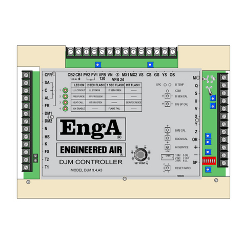
VI. POTS
DCAL (Pot 1)
Discharge Calibration (CW=colder)
BMSZ (Pot 2)
BMS zero. (CW=reduce)
CONT (Pot 3)
Control type. (CW=integral; CCW=proportional) (Usual setting for C-TRAC
control is less than 9 o'clock)
SER (Pot 4)
Service pot (CW=high fire)
IMPORTANT: When operating in the service mode, the burner will not cycle off.(See
section X.)
SP (Pot 5)
Discharge set point. (CW=colder) Adjustment range = 35 to 95°F.
BMSS (Pot 6)
BMS span. (CW = less gain)
NOTE: This adjustment is only used when a C-TRAC or other BMS type input signal is
wired to DJM2.4 terminals “+ and -” (including Metasys). (See section XI)

DJM2.4 MANUAL
8 Oct 00 R2
DJM2 Control
TE 6000
Discharge
Air Sensor
B
D
SP
OR
CURVE (Pot 7)
Curve matching. (CW = Increase O2 reading)
MINSP (Pot 8)
Combustion blower minimum speed. (CW = slower)
Pot 9 (not
visible)
Tachometer calibration (Factory Set for optimal light off speed
(CW=faster)
Pot 10 (not
visible)
Tachometer calibration (Factory Set)
Proportional/Integral Setting (CONT Pot 3)
The DJM2.4 is a Proportional and Integral (PI) controller. This type of control system will provide
stable temperature control with little deviation from set point. However when the DJM2.4 is used
with BMS control, the host system may already have an elaborate PID control scheme which could
react with the DJM2.4 PI control scheme. In this application, the DJM2.4 can be adjusted to
provide proportional only control. Pot 3 can be adjusted to vary the effect of Proportional and
Integral control schemes. When set in the full CCW position the control effect will be 95%
proportional. When set at the full CW position, the proportional effect will be 25%. With different
applications, slightly different settings may be required. Tests have indicated the best settings for
various applications are:
For use with Maxitrol TS114 or Johnson TE 6000-960 sensors this pot should be left in the
centre position (9 o’clock or less position).
For use with a building management control system, the pot should be set in the full CCW
(proportional) position. (This includes METASYS and similar controls.)
For use with the C-TRAC, the pot should be left set in the centre position
or just slightly CCW from centre (9 o’clock or between 7:30 and 9 o’clock).
VII. HIGH FIRE OVERRIDE
The DJM2.4 has a terminal marked "OR". When terminal
"OR" is jumpered to terminal "B" the unit will go to high
fire. This is usually activated by room thermostat.
NOTE: This is a jumpered high fire condition. During this condition the DJM2.4 will
not provide temperature control. If discharge temperatures exceed the
setting of the L4064 Honeywell High Limit control (located where the supply
air leaves the heat exchanger), the high limit will trip and turn the heat off.
VIII. STATUS LIGHTS
There are 3 LED lights that have different meanings based on the rate of flashing. The different
rates are defined as:
ON (Constant)
SLOW FLASH (2 second rate)

DJM2.4 MANUAL
9 Oct 00 R2
IRREGULAR (2 short ON flashes followed by a long off)
LED 1 (Pre-Purge)
ON The 50 second pre-purge timer is active.
OFF The heat exchanger ignition pre-purge is completed or there is no call for
heat.
SLOW FLASH There is trouble with the combustion air blower tachometer. The DJM2.4
is receiving a tachometer signal that is not consistent with the
combustion blower status. This can occur with a blown combustion fan
fuse or failed combustion fan motor as well as a faulty Hall Effect speed
sensor or a faulty magnet.
If the combustion blower is not running, first check the Hall Effect speed
sensor ensuring it has power and can respond to the magnet as described
under “Checking Speed Sensor” on page 24. Next remove all three wires
to terminals "OS, YS, and GS". If the motor starts, replace the speed
sensor. If the combustion blower fails to start, check the combustion
motor. Reconnect the speed sensor, fuse, and power.
If the combustion blower is running the tachometer signal is missing,
weak, or grounded. With a digital AC voltmeter, measure the AC volts
present on terminals "YS" to "GS". When the combustion blower is
running there should be 4 to 6 VAC present. If the AC voltage is not
present, check the tachometer sensor to magnet gap. It should be 1/16
to 1/8 inch. If the gap is okay, replace the speed sensor. Further
information found in section “Checking Speed Sensor” located on page
24. If the voltage is constantly 10 VDC and the sensor is located near the
magnet then the sensor if faulty (always “on”).
NOTE: No part of the speed sensor’s sensing element should be located over the
metal blower motor shaft. (See diagram section XV.)
If about 5 VAC voltage is present on YS and GS, note that the DJM2.4 is
sensitive to the shape of the waveform produced by the Hall Effect speed
sensor. A sensor with leakage to ground will provide a distorted
waveform, which will cause the DJM2.4 to reject the signal.
Sometimes a bad magnet or Hall Effect speed sensor will produce an
uneven waveform. Turning the magnet around and/or replacing the
speed sensor will correct this problem.
Refer to "Checking the Speed Sensor" on page 24 for further information.
LED 2 (Heat Call)
OFF There is no heat call.
ON There is a valid heat call and the system is allowed to function normally if
all systems downstream are operating correctly.

DJM2.4 MANUAL
10 Oct 00 R2
SLOW FLASH There is a heat call but the heat switch is open. (HS terminal).
IRREGULAR FLASH Terminals SV and SR are jumpered. The unit is in service mode.
LED 3 (Flame Relay or Ignition Enabled)
OFF The flame relay or ignition control device is not energized.
ON The flame relay or ignition control device is energized. The ignition
control device now has the responsibility to light the pilot flame, prove
the pilot flame, and energizing the main valve.
IX. BASIC BURNER OPERATION
Blower and Dampers
The DJM2.4 has no control of the dampers and supply air blower. They will be controlled by devices
external to the DJM2.4.
Burner
The basic burner-operating scheme is as follows.
1. Nothing happens until there is a call for heat and all the required heating operating conditions
are met. (Example: heat switch turned on.)
NOTE: During Service Mode operation or safety operation, this step is ignored.
2. When a heating call is received, before the combustion air blower is allowed to start, the
combustion blower tachometer (Hall effect speed sensor) is checked for a false signal. If no
signal is present, the combustion air blower is started.
3. After the combustion blower is started, the DJM waits until the blower reaches the correct pre-
purge speed (Approximately 3450 RPM).
4. When the correct speed is obtained, the pre-purge time delay is started. While the combustion
fan is operating in the pre-purge mode, the heat exchanger is purged of any unwanted gases
that may be present.
5. After the pre-purge cycle is complete, the combustion blower speed slows down to an
intermediate ignition speed. (For the standard round burner this is 2700 RPM, for the
rectangular high turndown burner is 2300 RPM.)
6. The DJM2.4 relay contacts across DJM2.4 terminals “CFR” and “FR” close to allow the flame
relay or ignition control device to be energized. The flame relay or ignition control device lights
the pilot by activating a spark and opening the pilot solenoid valve (which receives it's power
from the ignition control and the power passes through the DJM2.4 contacts "PV1" and "PV2").
The ignition control proves the pilot flame and then energizes the main gas valve. At the same
time the main gas valve is energized, a "feedback" signal is fed to the DJM2.4 on terminal
"VFB24" or “VFB120” depending on the gas valve voltage.
NOTE: At all times the combustion blower speed is continuously monitored. If any
problem is detected, the burner is shut off and the control logic goes to step 3.

DJM2.4 MANUAL
11 Oct 00 R2
7. After the main flame has been established, the combustion blower speed may slow down to
the low fire speed (standard round burner 1850 RPM, high turndown rectangular burner is 1250
RPM at 10:1 turndown and 1150 RPM at 15:1 turndown). After about 10 seconds, the pilot
solenoid contacts between DJM2 terminals "PV1" and "PV2" open and the AC power to the
pilot valve from the flame relay is turned off.
8. After lighting, the combustion blower speed and the gas valve voltage will modulate to
maintain the required discharge temperature while maintaining proper combustion.
9. If the heating demand is satisfied, the burner is cycled off. At this point, the combustion blower
returns to the intermediate light off speed. This is referred to as a "maintain purge mode".
(2700 RPM for the standard burner or 2300 RPM for the high turndown burner.)
NOTE: Opening the heat switch will also cycle the burner flame off. If this occurs, the
combustion blower will be continue running for 1 to 4 minutes to cool the
burner.
10. If at any time the combustion blower tachometer senses an insufficient blower speed, the pre-
purge timer is reset and the control logic goes to step 3.
11. If the discharge sensor initiates another call for heat within the next 4 minutes while the
DJM2.4 is operating in its "maintain purge mode", the control logic goes to step 6 and the
burner will re-light.
12. If there is no heat call within the 4 minute "maintain purge mode", the combustion blower is
shut off. If another call for heat is initiated at this time, the control logic returns to step 1.
Service Mode
When DJM2.4 terminals "SV" and "SR" are jumpered, the DJM2.4 is placed into service mode. An
irregular flashing on the (centre) LED Heat Call light indicates Service mode on the DJM2.4. When in
service mode, the burner will be brought on and held on and will not cycle off. Adjusting pot 4
“SER” will allow complete manual control of the burner-firing rate from low to high fire. This
operation is useful for troubleshooting or burner set-up.
Important Usage Notes Regarding the Service Pot and Service Mode
1. The unit must not be left in the service mode.
2. When leaving the unit make sure to remove the jumper from terminals SV and SR.
3. When in service mode, the burner will not cycle off.
4. An irregular flashing of LED 2 indicates that the DJM2 is in the service mode.
5. The supply fan contactor has to be powered on.
X. TEMPERATURE CONTROL –GENERAL OVERVIEW
The DJM2.4 is not designed for use with any application requiring reset signal such as Room,
Ambient, or BMS Reset. It will only accept one temperature-controlling signal at a time.
The DJM2.4 control signal can come from ONE of the following sources.
Maxitrol TS114 sensor and TD114 set point.

DJM2.4 MANUAL
12 Oct 00 R2
Johnson TE 6000 sensor and built in internal set point. (The DJM2.4 isn’t compatible with
Johnson’s TE 6100 room thermostat/set point.)
135-ohm slide wire electro-mechanical device.
Direct voltage or current input from BMS, MEGATRAC, or C-TRAC.
If more than one signal source is connected, the DJM2.2 will only respond to the temperature
control which is demanding the most heat. (The control is from one or the other. It is not a
calculated setting based on both sensors.) For example, it is possible to have both the BMS direct
voltage control and a Johnson TE 6000 sensor connected. In this application, the Johnson TE 6000
system could be set to operate with a set point of 45°F. As long as the discharge temperature is
over 45°, the DJM2.4 will only respond to the BMS voltage input. However if the temperature drops
below 45°F, the Johnson TE 6000 system will take over. In this application, the Johnson system will
act as a modulating low limit. Also refer to Section VII Proportional/Integral Setting, Pot 3 cont.
Control Types
Usually a C-TRAC, METASYS, or other control system will control the DJM2.4. However the DJM2.4
can operate as a stand-alone device. This is usually only done when the DJM2.4 is being used to
replace the older version DJM that is no longer being manufactured. Most new stand-alone
applications will use the DJM3.
DJM2.4 Controlled by DCV (C-TRAC, Metasys, etc.)
The C-TRAC pots are set as per the normal factory recommended settings. To set the DJM2.4
controlled by a C-TRAC: See Section XVIII “DJM2 Slaving From C-TRAC” for more information.
The C-TRAC pots are to be set as per the following assuming it is sitting horizontal (the label
"DJM2.4" is horizontal), then
"CONT" (Pot 3) would normally be set at about the 9 o'clock position (or midway on its stroke).
If you wish to set it more accurately by using instruments then follow these steps:
1. Slowly, starting from zero, increase the strength of the heat call signal onto the + and
input terminals. Stop at about 3 VDC. Adjust the BMSS pot (6) until the heat light just comes
on. If you cannot get the heat light to start, then adjust the BMSZ pot (2).
2. After the above is complete, increase the heat call to a full call. A full heat call will have an
input to the DJM2.4 + and terminals that is in excess of 8 VDC. If you are working with a
burner that has just been started it may take 2 minutes to reach high fire with the 8 VDC
signal due to internal control logic designed to reduce temperature overshoot by
modulating the burner slowly.
3. Then very slowly (over a minimum of 15 seconds) reduce the heat call to 2.5 VDC on the “+
and -” terminals. As you reach the area of 2.5 VDC the heat call light should cycle off. It may
take some time depending on the setting of the “CONT” pot. If the light does not cycle off
adjust the “CONT” pot to about the 7:00 o’clock position. If the light still does not cycle off,
adjust the “BMSZ” pot 2 slowly until the heat call light just cycles off.
4. Repeat the above steps to confirm operation.

DJM2.4 MANUAL
13 Oct 00 R2
XI. BMS CONTROL
See Section XII for information on BMS control wiring connections. Note the comments under the
following headings if a BMS or other DCV control device is connected to the DJM2.
"WIRING"(See section IV)
"PROPORTIONAL/INTEGRAL SETTING"(See section VI and X)
"TEMPERATURE CONTROL"(See section XI)
"BMS CALIBRATION AND SET UP"(See section XII and X)
BMS can be wired into either of the following two sets of terminals.
BMS WIRED TO "R" AND "W" (Use Only on Retrofitting Old DJM)
If the DJM2 is to be directly controlled by a building management control system using current or
voltage, and that signal is wired through a resistor network into terminals R and W, the control
power to H and N MUST come from an isolated and ungrounded transformer. This resistor
network is to reduce the input voltage to a 0-3.5 VDC signal. The control power to H and N must
come from an isolated and ungrounded transformer. The power to terminals HS and 3 must come
from the same power source as applied to terminal H. This will require an isolating relay be used.
As the DJM2 also has a set of true 0-10 VDC input terminals, it is best to use them instead of this
option (R and W terminals are not optically isolated).
BMS Wired Into "+" and "-" (Preferred Method)
If desired, the wiring may be changed such that the BMS or control voltage is wired to terminals “+
and -”. These terminals are optically isolated and will eliminate the requirements for a separate
ungrounded isolating transformer. The control providing the signal to the “+ and -” terminals needs
to be a 0-10 VDC signal that has capability of a 20 ma or stronger drive.
For new installations we recommend using terminals “+ and -”.
Remote wiring should be run using minimum size 22 ga shielded wire. For runs over 150 feet, the
use of minimum wire size of 20 ga-shielded wire is recommended. The shield should be grounded
at the controller end only. If the shield is grounded in more then one place then the shield is made
useless between the two grounds. Input impedance is 500 ohms. If the control driving the DJM2
cannot output enough power to drive the DJM2, then resistor R19 (680 ohms) located on the back
of the board (near the +/- terminals) will need to be cut. This will give 1500 ohm input impedance.
Not being able to drive is recognized by seeing an output from the BMS to the DJM2 of 10 VDC
when not connected but measuring much less at the DJM2 + and terminals when connected.
For new installations we recommend using terminals “+ and -”.
All DJM2 relay contacts are rated at 5 amps. The TRIAC output (combustion blower) will handle a
0.6 HP motor at 120 vac.
XII. BMS CALIBRATION AND SET UP
See section V about types of BMS control and set-up. If wired to a building
Comparison
(VDC) (MA)

DJM2.4 MANUAL
14 Oct 00 R2
management system the DJM2.4 has the ability to accept that as a control
signal if wired into + and - terminals. This is similar to the above set up
except the control source is different. (If controlled by a BMS, there should
be a discharge control device to stop discharge air temperatures exceeding
120°F to avoid high limit tripping. The BMS could reset its discharger signal
from an override: e.g. room temperature.)
The BMS voltage input can be wired two ways.
0
2
4
5
6
8
10
0
3
8
10
12
16
20
Method 1
(Old method used on original DJM controls and not recommended on the DJM2 unless it is desired
to continue to use it when retrofitting an old DJM.) Uses an external 33,000-ohm series resistor
and Ziener diode. This is the method used by the original DJM. This drops the 10-volt signal down
to about 3.5 volts (the signal used by the original DJM). Unless necessary to use method 1, it is
best to use method 2 (which is used on all new equipment. It is possible to use method 2 if
converting from a DJM to a DJM2.4).
Method 2
(Recommended for new designs) Uses no external components and has the input signal directly
connected to terminals "+" and "-". Method 2 is optically isolated and is the preferred wiring
method. As normally shipped from the factory, the DJM2.4 is configured to have an input
impedance of 500-ohms on the "+ and -" terminals. At 10 VDC input the current would be 20 mA.
If the host BMS system cannot source 20 mA, the input impedance can be increased to 1500-ohms
by removing (cutting) resistor R19 (680-ohms). This resistor is located next to terminals "+" and "-
". To gain access to R19 to cut it, the DJM2.4 must be turned over.
BMS Calibration
Refer to instructions in above section DJM2.4 Controlled by DCV in section X, regarding pot
settings and BMS calibration.
NOTE: These controls are calibrated at the factory and in most instances field
calibration is not necessary.
XIII. DISCHARGE SENSOR READOUTS, CALIBRATION, ETC.
If the DJM2 is being used as a stand-alone device, there are two possible devices used as a set
point. They are a Maxitrol series 14 set-point dial TD114 (which works in association with the
Maxitrol TS114 discharge air temperature sensor), or the built in set point (which is used with a
Johnson TE 6000-960 discharge air sensor).
When the Maxitrol or Johnson controls are used the “DCAL” pot can be used for calibration. Set it
to just turn the heat light on when the sensor and set point values match. Note additional
information about the TE6000 and the Maxitrol systems following.
If both a discharge air sensor/set-point and BMS (used as an override) are connected to the
DJM2.4, discharge calibration will be required as the discharge sensor will be acting as a
modulating low limit when the BMS is not calling for override. It should be calibrated with the

DJM2.4 MANUAL
15 Oct 00 R2
BMS signal at zero. The BMS signal should be calibrated as noted in section X. If the DJM2.4 is
being slaved to a C-TRAC, METASYS, or some other device, then there will not be a set point
connected to the DJM2.4. The setpoint is at the master control; therefore no discharge sensor
calibration is necessary.
TE6000 Sensor
If the system uses a TE 6000-960 sensor, it is wired with one side of the sensor to Terminal “B”
and the other side of the senor wired to both Terminals “D” and “SP”, then it is necessary to use
the set point on the DJM2.4. The set point is the small pot labelled “SP” (pot 5) and the setting is
as indicated on the label.
Using the Johnson TE 6000 series control, the DJM2.4 utilizes pot 1 (DCAL) as the "Discharge
Calibration" pot. Adjusting it CW = colder. With the burner-firing rate being stable (no hunting or
cycling) accurately measure the discharge temperature at the discharge temperature sensor.
Connect a DC meter to DJM2.4 terminals "OR" (positive) and "W". Set the discharge set point to
match the measured discharge temperature. Adjust pot 1 until the meter reading is 1.8 volts DC.
Note information below.
A second calibration method for the TE6000 without a meter is:
Ensure there is no signal (such as voltage on +/-) that would call for a higher discharge than the
temperature at the set point. Next, measure the temperature immediately next to the discharge
air sensor. Adjust the set-point dial (pot 5 labelled SP) to the same value as that measured at the
discharge sensor.
When this is complete adjust the DCAL (Pot1) until the heat light just goes off.
Sensor Resistance Chart for TE 6000-960
°C
°F
Resistance
°C
°F
Resistance
°C
°F
Resistance
-40
-40
602-605
18.3
65
983
48.9
120
1234
-34.4
-30
633
20
68
996
54.4
130
1269
-28.9
-20
665
20.6
69
1000.7
60
140
1333
-23.3
-10
698
21.1
70
1005
65.5
150
1365
-17.8
0
732
23.9
75
1026.5
71.1
160
1437
-12.2
10
768
26.7
80
1048
76.7
170
1491
-8.7
20
804
29.4
85
1070
82.2
180
1546
-1.1
30
842
32.2
90
1092
87.7
190
1602
4.4
40
881
35.6
95
1116
93.3
200
1659
10
50
921
37.8
100
1139
98.8
210
1718
12.8
55
941.5
43.3
110
1186
100
212
1778
Reference resistance is 1035 ohms at 77°F. Resistance tolerances are ±0.05 to 0.15% at 77°F.
Temperature range +32 to +104°F.

DJM2.4 MANUAL
16 Oct 00 R2
NOTE: Our design discharge temperature range is 30 to 140ºF, with about 55-75
being the usual set point.
Maxitrol Discharge Sensor/Selector
If the system uses a Maxitrol set point, the set point is that indicated on the TD114 dial. There is
also a calibration pot on the back of the Maxitrol dial. Its correct setting is such that the
resistance across the Maxitrol terminals 1 and 3 should be 10,000 ohms with the set point at 77°F
(25°C). The Maxitrol TS114 temperature sensor (calibrated to 10,000 ohms at 77 degrees also)
changes about 40 ohms per °F. As the sensor gets hotter, the resistance falls. If there is a long
wire run it may be best to calibrate the dial against a known sensor temperature due to wire
resistance.
XIV. BURNER SET UP
Burner Selection
The DJM2.4 is designed for use with either the standard circular DJ burner or the rectangular
shaped high turndown burner. Turn the board over to the backside. There is a jumper wire
located next to terminal "PV1" on the bottom backside of the board. If the DJM2.4 is to be used
with the high turndown burner this wire must be cut.
Combustion Set Up
The DJM2.4 is designed to operate with both the standard (round burner plate) and High
Turndown (rectangular) Burners. Cutting a jumper wire located next to terminal “PV1” makes the
selection. For high turndown burner operation, the jumper wire must be cut.
There are two pots located close to terminal SP, which affect the burner set up. These pots are to
be adjusted only by a qualified service technician using proper combustion analysis equipment.
Pot 7 (second pot from the right) is the curve matching pot. The curve matching pot is used to
match the modulating gas valve opening curve and the combustion blower fan curve. There are
three Maxitrol valves that can be used with the DJM2.4. Each of these gas valves has slightly
different opening characteristics. The curve matching pot is to be adjusted to compensate for
these differences.
Pot 8 (first pot from the right-labelled MINSP) is the low fire RPM adjustment pot. This pot is used
to provide some adjustment to the low fire combustion air. The low fire motor speed is
adjustable from 1150 to 1400 RPM (high turndown) and 1800 to 2000 (standard burner). The
recommended settings for the low fire speed are 1250 for the high turndown burner and 1830
for the standard burner.
NOTE: The light off RPM is fixed, non-adjustable. Adjusting the low fire speed will
have not effect on the light off speed.
Preview of Combustion Set Up
There are two burners available:
THE STANDARD (or Round) BURNER
Limited to about 2.5:1 turndown.

DJM2.4 MANUAL
17 Oct 00 R2
No jumper to be cut on DJM2.
Light off speed about 2700 RPM.
Modulation between 1850 and 3400 RPM.
THE HIGH TURNDOWN (Rectangular) BURNER
Capable of 15:1 turndown.
You must cut the jumper on the back of the DJM2 board. It is located next to terminal “P”
on the bottom of the board.
Light off speed about 2300 RPM.
Modulation between 1150 and 3400 RPM.
Note carefully which “M” series valve is in use.
FOR EITHER BURNER
When measuring combustion, ensure probe of analyser inserts fully into the flue
connection to the heat exchanger. Measuring at the flue outlet may be a diluted reading
due to air mixing into the flue.
First set up high fire
Then set up low fire
Adjust midrange firing (curve matching pot)
Adjust pilot
NOTE: If combustion is not set correctly it can result improper burning which may
produce products of combustion that smell, carbon and or an excessive
amount of water in the flue. Care should be taken to set burners up properly.
Note that temperature of the air and fuel may have a great affect on the set
up you select. If both the combustion air and the fuel are at a constant
temperature throughout the heating season, once combustion is set it should
remain similar through the season. However, this usually only occurs on
indoor units. Setting up an outdoor unit is not the same as setting up a unit or
a boiler inside a building.
When a unit is located outside, it is subject to different temperatures of combustion air and
fuel through the season. These temperatures affect the densities, thus affecting the resulting
combustion process. In some instances units that operate with 3% oxygen at -40° ambient
temperatures will be found to operate at 9% oxygen on an 80°F day. How the gas line is run
(indoors or across the roof) is the largest contributor to this problem.
It is better to have a burner that runs clean and doesn’t produce a lot of water from the flue
throughout the season then to set up for best efficiency. Also we recommend that the probe
for combustion analysis be placed directly into the heat exchanger outlet rather then in the
flue. This is because air can enter into the bottom of the flue and dilute readings in the flue.

DJM2.4 MANUAL
18 Oct 00 R2
Refer also to “Water and Ice from Combustion” on page 32 regarding another problem with
improper combustion set up.
High Turndown (Rectangular) Burner
HIGH FIRE SET UP
1. Place a jumper across the DJM2.4 terminals “SV and SR” to force the control into a
manual firing mode.
2. Set manual firing pot labelled “SER” (Pot 4
located near the middle of the panel) to high
fire by turning it fully clockwise. Ensure adequate inlet fuel pressure. Adjust the high fire
manifold pressure to that listed on the rating plate. Adjust the combustion air slider or
inlet damper until the high fire O2reading is between 3.5 and 4.2%. Tighten the locking
screw to keep the damper locked into this spot.
Add another locking screw if the damper moves from its position.
LOW FIRE SET UP
For both 10:1 and 15:1 turndown burners.
NOTE: Most high turndown DJ units will employ one of the following Maxitrol
modulating DC volt gas valves.
Series 20 - M520, M620. These valves do not have high fire regulators. High fire
pressure is set up at the appliance regulator.
Series 50 - M550, M650, ES350. These valves do not have high fire regulators. High fire
pressure is set up at the appliance regulator
ES345D-L This valve has a built in high fire regulator. Used on DJ140
models
The above valves differ from each other in size, configuration, BTU capacity, physical layout, and
low fire set up.
Check the unit you are working on to verify what type of modulating gas valve you have to ensure
the correct combustion set up method is used.
Top Loading - Ensure that there is a ¼" aluminium tubing connected from the top of the
modulating gas valve vent connection to the burner box. This is to guarantee that the varying
burner box pressure allows the proper flow rate through the modulating gas valve. Also ensure
that the small vent hole under the oval shaped cover is sealed off with silicone or Tremco tape.
When doing combustion analysis it is important that the top of the valve be sealed by either
reinstalling the cap after each adjustment, or placing your finger fully over the top to seal the
open top on the valve. The reason for this requirement is that the valve is “top loaded” which
means that the valve is having pressure from the combustion fan added to the top of the valve’s
diaphragm thus increasing the gas flow through the valve, especially at higher flow.
Series 20/ M520 and M620 (High Turndown)
As these valves have 2 low fire adjustments the following procedure should be followed
carefully:

DJM2.4 MANUAL
19 Oct 00 R2
1. Once the high fire pressure and combustion have been set up at point “B” above, turn the
manual firing pot (fully CCW) to achieve low fire
2. Adjust the low fire RPM pot 8 (MINSP) until the low fire speed on the combustion fan
motor is 1250 RPM ±10 RPM (20.8Hz) for 10:1 set up. [1150 RPM ±5 (19.91 Hz) for 15:1
turndown.] At this point the DC voltage reading at the modulating gas valve terminals
should be 0 VDC.
3. Under the cover on the Maxitrol series 20 valve is an adjustment screw (brass or silver)
that has a lock ring. Holding it in place, this lock ring uses a special tool (two very small
holes) to loosen it.
4. The lock ring needs to be loosened first. Turn it fully CCW, now turn the slot screw in the
centre of the lock ring (spring activated low fire adjustment) full CCW.
Caution: Do not over torque this screw at the top or bottom of its adjustment or it
will break the “c-clip” inside the valve, thus allowing the spring to ride free.
5. Adjust the low fire bypass screw at the bottom side of the valve body until the O2reading
is between 16.0% to 16.5%. (16.5 to 17.5% oxygen for 15:1 turndown.) At these settings
the turndown will be very close to 10:1. The maximum CO at low fire is 80 PPM.
6. Adjust the manual firing pot 4 SER up very slowly until the DC volts at the modulating gas
valve terminals are about 2.25 VDC. If the voltage rises over 2.25 VDC while adjusting the
manual pot, turn it down and start again from less than 1.5 VDC until 2.25 VDC is reached.
7. Check the O2reading again at this point. If the O2has increased, adjust the spring
activated low fire adjustment on top of the valve until the O2reading is same as the low
fire reading at 0 VDC (you are correcting for valve hysteresis with this adjustment).
8. CURVE MATCHING PROCEDURE
Switch to high fire setting (approximately 3450 RPM or 57.5 Hz) for 1 minute. Adjust the
manual firing pot 4 SER down very slowly until the combustion motor speed is about 3060
RPM (51 Hz). Let the burner stabilize for 2 minutes and re-check the O2reading. If the O2
has dropped to less then the original high fire O2reading, adjust the curve matching pot
(labelled “CURVE”, second from the right on the bottom row, pot 7). Adjusting the CW
increases the O2reading. As the curve matching pot is adjusted the voltage to the gas
valve changes.
9. If the curve matching pot is adjusted to the fully CW position and the O2reading is still not
within 10% of the original High Fire O2reading, add a 180 ohm, 2 watt resistor across the
modulating gas valve terminals and repeat above test until proper curve matching is
achieved. (A 150-ohm, 2-watt resistor may have to be used if O2level still does not rise to
within 10% of original high fire O2reading.)
Switch burner to low fire again and re-check low fire, both at 0 VDC and 2.25 VDC. (An
addition of a resistor above may have changed the low fire setting if it was needed).
10. Lock the locking ring on the spring activated low fire adjustment screw. Failure to lock it
may cause the screw to vibrate loose allowing low fire gas pressure to increase. This can

DJM2.4 MANUAL
20 Oct 00 R2
create sooting of burner parts and the heat exchanger. If the locking ring is missing, drop
one drop of Loctite thread locker 222 onto the brass screw threads.
Series 50/M550, M650 AND ES350 (High Turndown)
These valves have only 1 low fire adjustment (spring activated low fire).
NOTE: These valves are not used on 15:1 turndown.
11. The high fire combustion set up is similar to the above except there is no low fire bypass
adjustment on the bottom of these valves. You may simply set up low fire by turning the
manual firing pot 4 SER to the low fire position (1250-RPM ±10 RPM 20.8 Hz). Voltage to
the series 50 valve should be 0 volts DC. Adjust the spring activated low fire adjustment at
the top of the modulating gas valve (small screw) until an O2reading of 16.8% to 17.5 % is
achieved.
12. Lock the low fire adjustment screw as described in point 7 above, and then adjust the
curve matching pot 7 as in points 8 and 9 above.
Type ES345D-L (High Turndown)
As this valve has 2 low fire adjustments the following procedure should be applied.
NOTE: This valve can be used on 15:1 turndown.
13. After high fire is set up as in “2” (on Page 18), bring the unit to low fire by adjusting the
DJM2 “Service” pot 4 (SER) fully CCW. Turn the ES345 low fire adjustment screw found
under the valve cover near the wire terminals, fully CCW. Adjust DJM2 pot 8 (MINSP) until
the combustion fan is turning 1250 RPM ±10 RPM (20.8 Hz) for 10:1 turndown, [1195 RPM
±5 RPM for 15:1 turndown (19.91 Hz)]. Voltage to the ES valve should be 0 volts DC. The
low fire bypass adjustment on this valve is under the top cover on the large port and the
adjustment inside it is marked:
Increase Decrease
After removing the cover, loosen the locking screw first before making adjustment. The
low fire adjustment should be done at 0 VDC to the modulating gas valve terminals and
the spring activated low fire brass screw turned fully CCW and the locking ring loosened
off.
14. Bring voltage to gas valve at 2.25 VDC and adjust the spring activated low fire adjustment
located in the head with the electric modulator (smaller screw under cap) to achieve the
same O2reading as the one achieved at 0 VDC (16.8% to 17.5% O2). After this is complete
then adjust the curve matching pot 7 curve as described in points 8 and 9 above.
Pilot Set Up (High Turndown)
1. On high turndown units, ensure air tube to pilot is free of debris and blockages and then
set pilot pressure to 3.5" WC.
2. Pilot set up on high turndown burners is not as critical as there is not as much heat to
damage the pilot assembly as on the regular round burner.
Table of contents
Other EngA Controllers manuals
Popular Controllers manuals by other brands
KEBCO
KEBCO COMBIVERT F5 Series Installation guide & operation manual
digitalview
digitalview SVP-1280 instructions
Tolomatic
Tolomatic IMA-S Series manual
KS DIGITAL
KS DIGITAL KSD-RC quick start guide
Pegasus Astro
Pegasus Astro Dual Motor Focus Controller v3.x manual
wattstopper
wattstopper LS-101 quick start guide
Allen Organ Company LLC
Allen Organ Company LLC Classic R-10 quick start guide
Aqua Medic
Aqua Medic EcoDrift Wireless Master Operation manual

Bigassfans
Bigassfans HAIKU quick start guide
red lion
red lion DA70D installation guide
HANYOUNG NUX
HANYOUNG NUX TPR-2SL instruction manual
Intech Instruments Ltd
Intech Instruments Ltd IN-RTB installation guide
