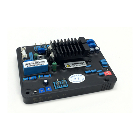
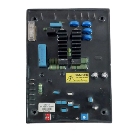
ENGGA EVC800i Guide

EVC800i AUTOMATIC VOLTAGE REGULATOR
SPECIFICATIONS
The EVC800i is a 3 Phase full wave, pulse width modulated type of Automatic Voltage Regulator for regulating the voltage
of Brushless Generator.
Excitation power can be derived from a shaff mounted 3 Phase premanent generator (PMG) or stator winding or Auxillary
winding. Internal electrical isolation is created between the PMG inputs and sensing inputs of AVR. This isolation with the
PMG assures the performance of the AVR against Non linear loads and reduces the Radio frequency interference on the
generator terminals. The PMG supply enables the generator to maintain current into a short circuit.
Sensing to AVR is directly from main winding. This signal is used to control the power fed to the exciter stator (and hence
to the main rotor) to maintain the generator output voltage within the specified limits. Provision is made for the connection
of remote potentiometer allowing the user to find control generator output voltage.
Built up of generator output voltage is fully under control manner keeping excitation current within limits and with soft start.
A frequency measuring circuits continually monitors the speed of the generator to provide low speed protection to the
excitation system. It reduces generator output voltage proportionally with speed below an adjustable threshold as per volt
per hertz slope. This slope is provided adjustable and adjusted by DIP adjustment trimmer. In addition to DIP, an delayed
voltage recovery (DWELL) is provided to improve speed recovery time when generator is used in conjunction with Turbo
charge engines. Generator overload circuit cuts off the excitation power in the event of excessive load on generator or
malfunctions. AVR observe overload condition for 20 seconds and after that cuts off the field voltage.
This condition remains latched until the generator has stopped.
For connecting 2 or more generators in parallel, quadrature droop and analog inputs provide reactive power sharing
controls.
Specification, Installation & Adjustment Manual
DESCRIPTIONS
Sensing Input
Power Input
Output
Built up Voltage
Voltage Regulation
Response Time
V - V for 220 Vac,
V - V for 400 Vac, 350 to 480Vac, 50/60Hz
PMG : 160 to 250 V, 3 Ph, 50 to 400 Hz.
Main Winding : 160 to 250 V, 1 Ph
Auxillary : 160 to 250 V, 1 Ph
Voltage : 180 Vdc on Input of 200 Vac
Current : Continuous 8 Amps
Residual Voltage : >4 Vac at AVR terminal
: < 1 % RMS
: < 20 mSec
0 200
380
180 to 250Vac, 50/60Hz
±
7 to 18 Ohms.
Maximum Input : ± 5Vdc
Sensitivity : 1 Volt for 2 % generator Volts
0
Field Resistance
Analog Input
Burden : 0.25 Ohms
Maximum Sensitivity : 1 Amp for 10 % Droop
Maximum Input : 2 Amps
Factory setting : 47 Hz with Switch 2 OFF
57 Hz with Switch 2 ON
Slope : 100 - 300 % down to 25 Hz
: 1%Hz = 1%Volts to 1%Hz=3%Volts
: Adjustable from 0 to 45 V in 4 Sec Max.
Operating Temperature : -40 to +70 C
Storage Temperature : -40 to +90 °C
Relative Humidity : Max. 95%
Vibration : 3.3Gs @ 100-2K Hz
175 mm L x 129 mm W x 37.5 mm H
XXXX
External Volts Adjustment
Atleast ± 10 % with 100 K Ohms 1 Watt trimmer
°
Droop Input
Under frequency protection
DIP
DWELL
Environment
Dimension and Weight
AVR CONTROL FUNCTION
CONTROL:
VOLT
STAB
UFRO
TRIM
DROOP
EXC TRIP
DIP
DWELL
SW1-ON
SW1-OFF
SW2-ON
SW2-OFF
FUNCTION:
To adjust generator output voltage
To prevent voltage hunting
To set under frequency Roll Off knee point
To match AVR input to Accessory Input
To set voltage Droop to 10% at 0.8 PF
To set the over-excitation protection Trip level
To adjust frequency related voltage Dip
To set the rate of voltage recovery time
To add fix response time
Response time as per STAB Pot
To set UFRO knee point at higher frequency
To set UFRO knee point at lower frequency
DIRECTION:
Clockwise increases output voltage
Clockwise increase in response
Clockwise increases knee point frequency
Clockwise increases AVR sensitivity
Clockwise increases the Droop
Clockwise increases the Trip level
Clockwise increases the Dip
Clockwise lengthens the recovery time.
SW1-ON : Increase in response time for 60 Hz
SW1-OFF : Response time for 50 Hz
SW2-ON : UFRO set at higher frequency
SW2-OFF : UFRO set at lower frequency
10/02/2015Page 1 of 9

EVC800i AUTOMATIC VOLTAGE REGULATOR
AVR SETTING
Before installing, adjusting or using this product it is important that you read the content of this manual and also become
familiar with the equipment.
Observe all cautions and warning notices
Caution Caution refers to a hazard or unsafe method or practice which can result in product damage.
Warning refers to a hazard or unsafe method or practice which can result in injury or death.
*
Warning This AVR has capacitors which have stored charge present even after stopping the generator and
can remain charge for upto 5 minutes. Terminal F+, F-, P1, P2 and P3 are linked to this charged
capacitor, so do not work on the wiring of AVR or machine until this time has elapsed.
Warning
Do not operate the equipment with the protective generator terminal cover removed.
* All work and adjustment must be carried out by skill technician using instruments and equipments which are regularly
checked for safety.
* Before carrying out any maintenance work, disable engine system, automatic closure circuit and turn off anti
condensation heaters.
* Never expose Live connections unless you have created safe working area around you.
Specification, Installation & Adjustment Manual
SAFETY PRECAUTIONS
Most of the AVR adjusments are factory set in positions which will give satisfactory performance during installation of
generator. But to achieve optimum performance under operating conditions, adjustment of some setting is required and
details are as below :-
The generator output voltage is set to 400 V at the factory but can be altered by adjusting Volt control or by external
trimmer
If a replacement AVR has been fitted or voltage setting is not known then proceed as below:-
1. Before running the generator ensure that the suitable voltmeter is available to measure generator output voltage.
2. Turn the VOLTS control fully anti-clockwise and turn the external hand trimmer (if fitted) to its Midway position.
3. Turn the STAB control to its Midway position.
4. Start the generator set, and run at no load condition at nominal frequency e.g. 50 or 60 Hz.
5. If UFRO LED is ON refer to the UFRO setting.
6. If O/L LED is ON refer to the O/L setting.
7. Carefully turn the capital VOLTS controls clockwise until rated voltage is reached.
8. If voltage instability is present refer to STAB adjustment and then re-adjust the generator voltage if necessary.
Warning During testing it is required to adjust controls which are very near to Live terminals or components.
Only personnel qualified to perform Live electrical service should carried out the testing or
adjustment.
Voltage [VOLTS] Adjustment :
Caution Do not increase the voltage above the rated voltage of the generator.
Stability [STAB] Adjustment :
The AVR Stability circuit ensure good steady state and transient
performance of the generator. In addition to STAB adjustment pot,
SW1 is also provided to quickly change the response of the stability
circuit to suit 50 or 60 Hz application.
The correct setting of the stability control can be achieved as
follows:-
1. Before running the generator select appropriate Sw1 position as
per the frequency of the generator.
2. Turn the STAB control to its mid-way position.
3. Run the generator at no load.
4. Slowly turn STAB control clockwise until the generator voltage
become unstable.
5. Slowly return the STAB control anti-clockwise until the voltage
is again stable.
6. Continue to rotate 2 more point anti-clockwise and this is the
correct running position.
10/02/2015Page 2 of 9
1 to 2 Points More Anti-Clockwise
From The Most Stable Point
Stable Point
Voltage
0 50 100
Clock Wise End
Anti Clockwise End Rotations

EVC800i AUTOMATIC VOLTAGE REGULATOR
Specification, Installation & Adjustment Manual
10/02/2015Page 3 of 9
Voltage
37 38 39 40 41 42 43 44 45 46 47 48 49 50
Knee Point
Frequency
Under Frequency Roll Off [UFRO]
V/Hz slope [DIP] Adjustment
Dwell [DWELL] Adjustment
Droop [DROOP] Adjustment.
The AVR incorporation an under speed protection circuit for “Volts
per Hertz” characteristics when the generator speed falls below an
adjustable threshold. Under normal circumstance it would not be
necessary to adjust the factory setting of this control, but using
SW2, 47 or 57 Hz is quickly adjusted.
To re-adjust the UFRO knee point then proceed as follows:-
(It will be necessary to adjust the generator / engine speed during
this procedure)
1. Run the generator at no load and at nominal frequency (50 or
60 Hz)
2. Turn the UFRO control fully anti-clockwise (The red led should
be OFF)
3. Run the generator at required knee frequency (Typically 47 or 57 Hz)
4. Turn the UFRO clockwise until the led illuminates.
5. Return the UFRO control slowly anti-clockwise until the Led just turn off.
6. UFRO adjustment is now complete.
The DIP adjustment controls the amount of frequency related
voltage
dip. This feature is useful when the generator is coupled with the
turbo charged engines with limited step load acceptance capability.
This features only operate when the speed is below the UFRO
knee point and works by increasing the V/Hz slope to give greater
voltage dip in the proportion of falling speed. This also reduce KW
on the generator and helps recovering the falling speed.
With the DIP control fully anti-clockwise the generator voltage
characteristic will follow minimum V/Hz line as the frequency falls
below nominal. (1%Hz=1%V)
Turning the DIP clockwise creates a greater slope in the V/Hz
Characteristics thus aiding engine speed recovery.
The dwell function introduces a time delay between the recovery
of voltage and recovery of speed. The purpose of the time delay
is to reduce the generator KW below the available engine KW
during the recovery period, thus allowing the speed recovery.
Again this control is only functional below the “knee point”, i.e if
the speed stays above the knee point during load switching there
is no effect from the DWELL function setting. Thus function is
mostly used when the generator coupled to turbo charged
engines with limited block load acceptance.
When the DWELL control fully anti-clockwise the generator voltage
will follow the V/Hz line as per UFRO setting. Turning the DWELL
control increases the delay time between the speed recovery and
voltage recovery. The voltage recovery can be held back for several seconds using this switcher.
Generator intended for parallel operation are fitted with quadrature Droop current (CT) which provides a signal for AVR
allowing each generator to share reactive current. The CT is connected to S1 and S2 on the AVR. It is important to
match the generator no load voltage to within 1% of each other, to ensure good reactive load sharing. The Droop
adjustment is factory set to 0% so that during solo operation there is no voltage drop. With the control fully clockwise
is maximum Droop.
For synchronizing, Droop setting procedure is as below:-
1. Run the generator at 50% rated current at any power factor between 0.8 legging and 1.0, ensure that generator rated
current value gives a maximum rating for the frame size without any direct factor.
2. Adjust Droop control such that there is voltage drop of around 3 to 3.5% of the no load voltage.
3. Repeat above sets with the second generator also.
4. Now Droop adjustment is complete with both the set and can be synchronized.
Voltage
37 38 39 40 41 42 43 44 45 46 47 48 49 50
Knee Point
1%Hz = 1%V
1%Hz = 3%V
Voltage
Knee Point
Time

EVC800i AUTOMATIC VOLTAGE REGULATOR
Specification, Installation & Adjustment Manual
10/02/2015Page 4 of 9
Trim [TRIM] Adjustment
Caution Any signal connected to this input must be fully floating and earth free.
Over Excitation [O/L] Adjustment
1. V0 - V200 - V380
2. Excitation Output F+, F- :
3. Power Input :
4. Current Compensation Input S1 and S2 :
5. External Voltage Adjustment VR1-VR2 :
6. Analog Input A+ and A- :
7. Dip Switch : SW1 - ON :
SW1 - OFF :
SW2 - ON :
SW2 - OFF :
An auxiliary input is provided to connect to power factor controller or any other type of PLC controller and is design to
accept DC signal upto +/-5 V.
The DC signal present to this input adds to or subtracts from the AVR reference circuit input and allows the external
controller to alter the generator excitation. The TRIM control allows the user to determine how much control the external
signal has over the AVR. With the Trim control fully clockwise the external signal has full control, with the trim control
fully anti-clockwise has no control.
The AVR includes the protection circuit to remove generator excitation in the event of over excitation, this condition is
usually a result of overload and can damage the rotor component within the generator. The excitation is cut of after a
delay of 20 seconds. During this time delay the overload condition should be continuous. Clockwise rotation of the O/L
control increases the excitation trip level. An over excitation trip condition is indicated by Red LED. The generator must be
stopped to reset the overload trip condition.
: When the generator output voltage required is 220Vac, connect the
sensing input to the terminal V0 and V200. When the generator output voltage requires 400Vac, connect the sensing
input terminal V0 and V380.
Connect Brushless exciter field to terminals F+ and F-, be sure to observe polarity.
AVR power input is on P1, P2 and P3. Input can be 1 Phase or 3 Phase. 3 Phase PMG can be
connected directly to P1, P2 and P3. Without PMG, Main Winding can be used as a power input. In that case for 400V
system connect U to P1 and N to P2. For 200V system connect U to P1 and W to P2. If auxiliary winding is there, then
that can also be used to power the AVR.
Current transformer of In:1A is connected to this terminal for parallel
operation.
If remote adjustment is required then connect a 100K/1W potentiometer to
terminal VR1 and VR2. VR1 and VR2 are left unconnected if remote pot not in use
5Vdc from external controller is connected to A+ and A-
Increases response time. Can be used for 60 Hz machine to increase the response time
(Slow response) or with 220V system when slow response is needed.
Response as per STAB pot set
60 Hz
50 Hz. As per STAB pot set
Sensing Input Terminal
±
WIRING

EVC800i AUTOMATIC VOLTAGE REGULATOR
Specification, Installation & Adjustment Manual
10/02/2015Page 5 of 9
DRAWING
MECHANICAL SPECIFICATION
SW1: ON - Increase in Response Time.
OFF - Response as per STAB pot Set
SW2: ON - 60 HZ
OFF -50 HZ
175 mm
129 mm
143 mm
104 mm
VR
A2
A1
S2
S1
1
VR2
FUSE 8 Amps
4 X 4.4 mm
F-F+ V220 V380
38mm
H
V0
175 mm
129 mm
143 mm
104 mm
ENGGA
DROOP UFRO
TRIM STAB VOLT
www.engga.com.cn
Model EVC800i
Sensing Input V - V for 220 Vac , 180 to 250Vac, 50/60Hz
0 220
V - V for 400 Vac , 350 to 480Vac, 50/60Hz
Power Input 160 to 250Vac
Output 180Vdc , 8A
0 380
:
:
:
:
Outline Drawing
The Drawing For Trimmer
F-
F+ V220
V0V380
P3
P2
P1
1
2
ON
P1 P2 P3
O/L O/L
LED
DIP DWELL

EVC800i AUTOMATIC VOLTAGE REGULATOR
Specification, Installation & Adjustment Manual
10/02/2015Page 6 of 9
P2
F- F+
V220
V380
VR
A2
A1
S2
S1
1
VR2
FUSE 8 Amps
Exciter
Field
+
-
Armature Stator Wire
W
N
V
U
+ 5 Vdc
-
CT
5A
IN :
100K/1W
V0
Connection Diagram with PMG Operation
Note : All doted lines are optional connections.
SW1: ON - Increase in Response Time.
OFF - Response as per STAB pot Set
SW2: ON - 60 HZ
OFF -50 HZ
P3 P1
1
2
ON
P3
P2
P1
PMG
O/L O/L
LED
DIP DWELL

EVC800i AUTOMATIC VOLTAGE REGULATOR
Specification, Installation & Adjustment Manual
10/02/2015Page 7 of 9
AUX
P2
F- F+
V220
V380
VR
A2
A1
S2
S1
1
VR2
FUSE 8 Amps
Exciter
Field
+
-
Armature Stator Wire
W
N
V
U
+ 5 Vdc
-
CT
5A
IN :
100K/1W
V0
Connection Diagram with Auxiliary Winding
Note : All doted lines are optional connections.
SW1: ON - Increase in Response Time.
OFF - Response as per STAB pot Set
SW2: ON - 60 HZ
OFF -50 HZ
P3 P1
1
2
ON O/L O/L
LED
DIP DWELL

EVC800i AUTOMATIC VOLTAGE REGULATOR
Specification, Installation & Adjustment Manual
10/02/2015Page 8 of 9
P2
F- F+
V220
V380
VR
A2
A1
S2
S1
1
VR2
FUSE 8 Amps
Exciter
Field
+
-
Armature Stator Wire
W
N
V
U
+ 5 Vdc
-
CT
5A
IN :
100K/1W
V0
Connection Diagram with Main Winding
Note : All doted lines are optional connections.
SW1: ON - Increase in Response Time.
OFF - Response as per STAB pot Set
SW2: ON - 60 HZ
OFF -50 HZ
P3 P1
1
2
ON O/L O/L
LED
DIP DWELL
Connection option for 400V system
Connection option for 200V system
Table of contents
Other ENGGA Controllers manuals
Popular Controllers manuals by other brands
Dover
Dover All-Flo PSG 72000-00 Installation operation & maintenance
Altronix
Altronix Maximal3FD installation guide

ENERGEN
ENERGEN P8 User manual and safety information
Holman
Holman CLXRGB60 user guide

Comnet
Comnet FVT109B Installation and operation manual
Honeywell
Honeywell S7014A Series quick start guide
Projecta
Projecta INTELLI-START IS3000 instructions

Dungs
Dungs GasMultiBloc MB-ZRD B07 Series Operation and assembly instructions
Johnson Controls
Johnson Controls Tyco Kantech KT-400 Connecting guide
THORLABS
THORLABS BPC301 user guide
SPINEA
SPINEA DRIVESPIN Series Operation manual
Emerson
Emerson FISHER FIELDVUE DLC3010 quick start guide
