ALF-14020-E-02 All-Flo4
SECTION 2
PRINCIPLES OF OPERATION
The 72000-00 controller is engineered to provide control of the number
of times a solenoid pump fully discharges both liquid chambers, referred
to as a “cycle”, in a batching application. It also controls the speed that
the pump cycles, how many “Batches” are in an operation, and the
interval of time between batches. This allows for greater control and
repeatability of your All-Flo pump. The pump speed can be adjusted
using the buttons on the controller’s keyboard and preset batch
operations can be made to ensure a quick set up.
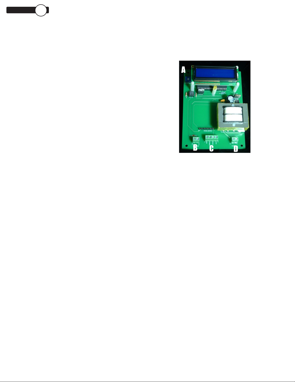
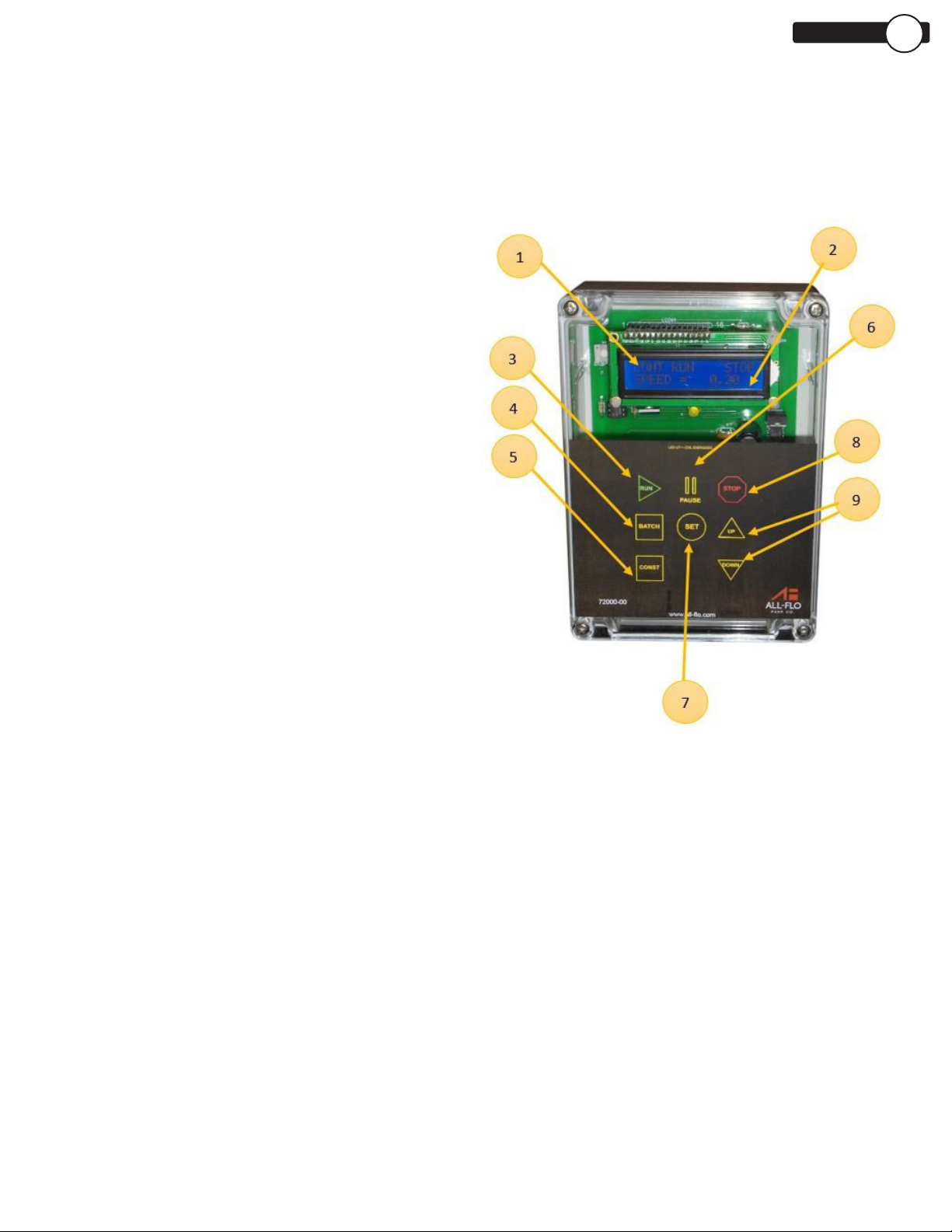
72000-00 BATCH CONTROLLER
All-Flo’s solenoid pumps use the compressed air to displace fluid in the
same way as a standard Air Operated Double Diaphragm (AODD) pump
while using electric pulses to control the pump speed. The use of a
solenoid pump allows the user to have more control over the operation.
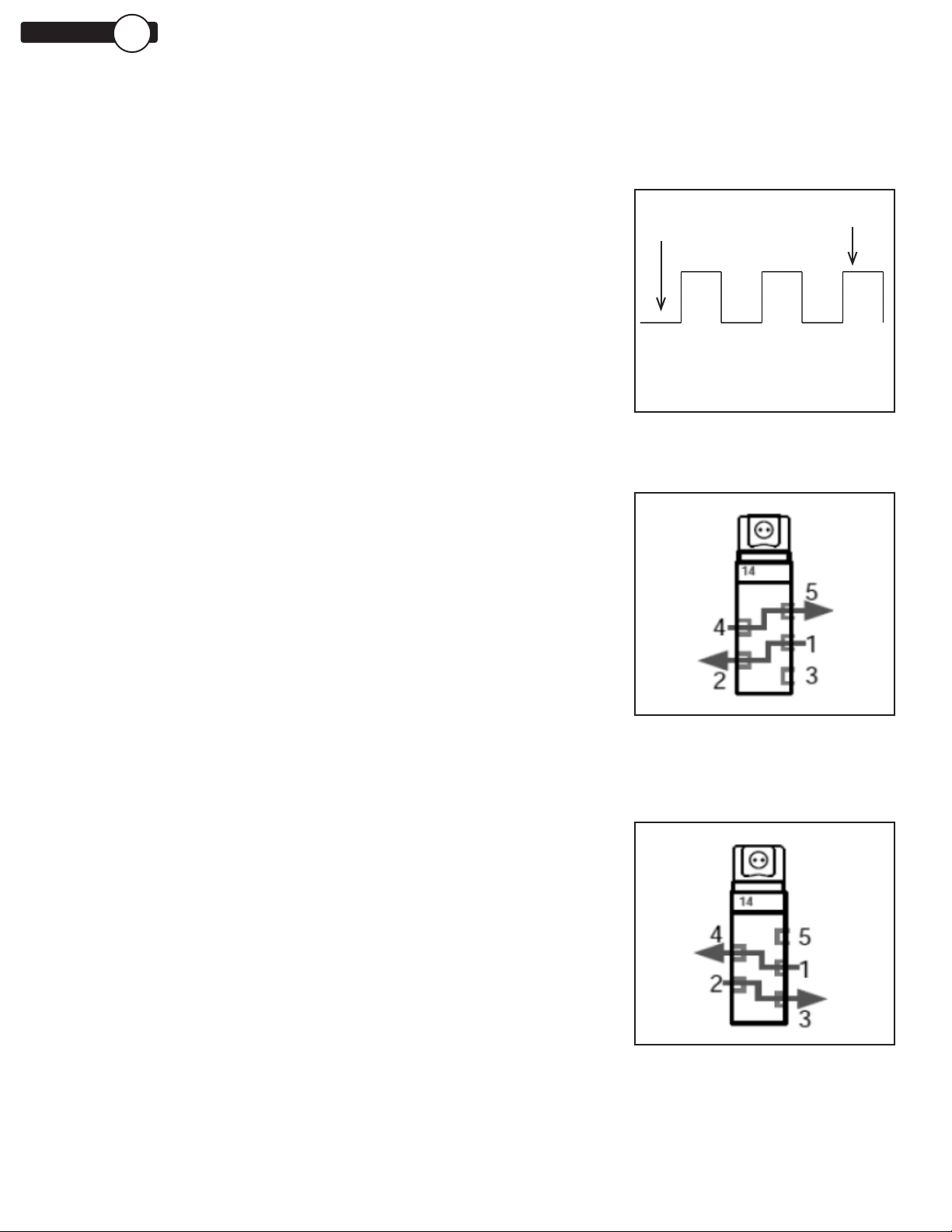
The solenoid pump uses an electrical pulse to energize the solenoid
valve attached to the air end of the pump. These electronic pulses are
sent in the form of a square wave (Figure 1).
The energized pulses move the solenoid valve connecting the different
ports changing how the air flows. In Figures 2 and 3, port 1 denotes the
connection to the air supply, ports 2 and 4 denote the ports leading the
air chambers, and ports 3 and 5 denote the ports that are open to the
atmosphere.
While the solenoid is de-energized, the valve sits at its standard position,
allowing pressurized air from the air supply (port 1) into one of the
air chambers of the pump (port 2). The other air chamber (port 4) is
connected the exhaust (port 5), discharging any pressurized air in that
chamber.
When the pulse is received, the solenoid energizes and moves the valve
to its energized position (Figure 3).
While the solenoid is energized, the pressurized air from the air supply
(port 1) flows into the air chamber of the pump (port 4). The other air
chamber (port 2) is connected the exhaust (port 3), discharging any
pressurized air in that chamber.
This pulsating energized and de-energized states mimics the air flow
cycle cause by the pilot sleeve in the standard pump. The faster these
pulses are applied, the quicker the pump operates.
ALL-FLO’S SOLENOID CONTROLLED PUMPS
FIGURE 3
ENERGIZED
SOLENOID POSITION
FIGURE 2
DE-ENERGIZED
SOLENOID POSITION
FIGURE 1
SQUARE WAVE
Energized
De-energized