Enginko MCF-LW13IO User manual

2022/08/30 06:23 1/2 manual_mcf-lw13io
e n g i n k o . s u p p o r t . c e n t e r - https://www.enginko.com/support/
Table of Contents
MCF-LW13IO Operating Manual 1 ..................................................................................................
1. Description 1 ................................................................................................................................
2. Overview 2 ....................................................................................................................................
2.1 Technical data 2 .........................................................................................................................
2.2 Installation 3 ..............................................................................................................................
2.3 Power supply 4 ...........................................................................................................................
2.4 Configuration 4 ..........................................................................................................................
2.5 System leds 5 .............................................................................................................................
2.6 Firmware update 6 .....................................................................................................................
3 I/O 6 .................................................................................................................................................
3.1 Input 7 ........................................................................................................................................
3.2 Output 7 .....................................................................................................................................
3.3 Wiring examples 8 .....................................................................................................................
4 LoRaWAN® network 9 ..................................................................................................................
4.1 Activation 10 ..............................................................................................................................
4.2 Other settings 10 .......................................................................................................................
5 Passwords 13 .................................................................................................................................
6 Configuration file 15 .....................................................................................................................
6.1 Multi devices configuration 16 ...................................................................................................
7 LoRaWEB Tool 17 ...........................................................................................................................
8 Payload 18 ......................................................................................................................................
9 Ordering code 18 ...........................................................................................................................
10 Declaration of conformity 18 ....................................................................................................
11 FCC compliance for MCF-LW13IO-US 18 ..................................................................................
12 Contacts 19 ..................................................................................................................................

Last update: 2022/01/25 10:24 manual_mcf-lw13io https://www.enginko.com/support/doku.php?id=manual_mcf-lw13io&rev=1643102686
https://www.enginko.com/support/ Printed on 2022/08/30 06:23

2022/08/30 06:23 1/19 manual_mcf-lw13io
e n g i n k o . s u p p o r t . c e n t e r - https://www.enginko.com/support/
MCF-LW13IO Operating Manual
Important safety information
Read this manual before attempting to install the device! Failure to observe
recommendations included in this manual may be dangerous or cause a violation of the
law. The manufacturer will not be held responsible for any loss or damage resulting from
not following the instructions of this operating manual.
Do not dismantle or modify in any way.
Avoid mechanical stress
Do not use any detergent or alcohol to clean the device.
Do not mount in horizontal position.
Disposal information for users
Pursuant to and in accordance with Article 14 of the Directive 2012/19/EU of the
European Parliament on waste electrical and electronic equipment (WEEE), and pursuant
to and in accordance with Article 20 of the Directive 2013/56/EU of the European
Parliament on batteries and accumulators and waste batteries.
The barred symbol of the rubbish bin shown on the equipment indicates that, at the end of its useful
life, the product must be collected separately from other waste.
1. Description
The MCF-LW13IO is a LoRaWAN® actuator that allows to switch ON and OFF a 230Vac~, 8A load. It
also reads the status of a 230Vac~ input. This device can transmit the status of its input and control
the output through the LoRaWAN® network. It can be used for industrial process control and home
automation, water treatment, agriculture irrigation and similar applications. Input can be used as
pulse counter.

Last update: 2022/01/25 10:24 manual_mcf-lw13io https://www.enginko.com/support/doku.php?id=manual_mcf-lw13io&rev=1643102686
https://www.enginko.com/support/ Printed on 2022/08/30 06:23
2. Overview
2.1 Technical data
CPU Cortex M0+
EEProm 32KB
Flash 64KB
Real time clock
Encryption AES 128 bit
Class C LoRaWAN® stack EU868, AS923, AU915, US915
EU868 version CE certified according to 2014/53/EU – Radio Equipment Directive (RED)
US915 version FCC compliant
Transmission band (EU version): 868 MHz
Transmission Power (EU version): 14dBm max
Power supply 110÷230Vac~ 50/60 Hz
Power consumption 1W
1 opto-isolated input, 230Vac
1 relay output with COM, NO, NC contacts, 8A@230Vac~
NFC for node setup ad FW upgrade
Storage temperature range -20°C ÷+80°C
Working temperature range -10°C ÷+70°C
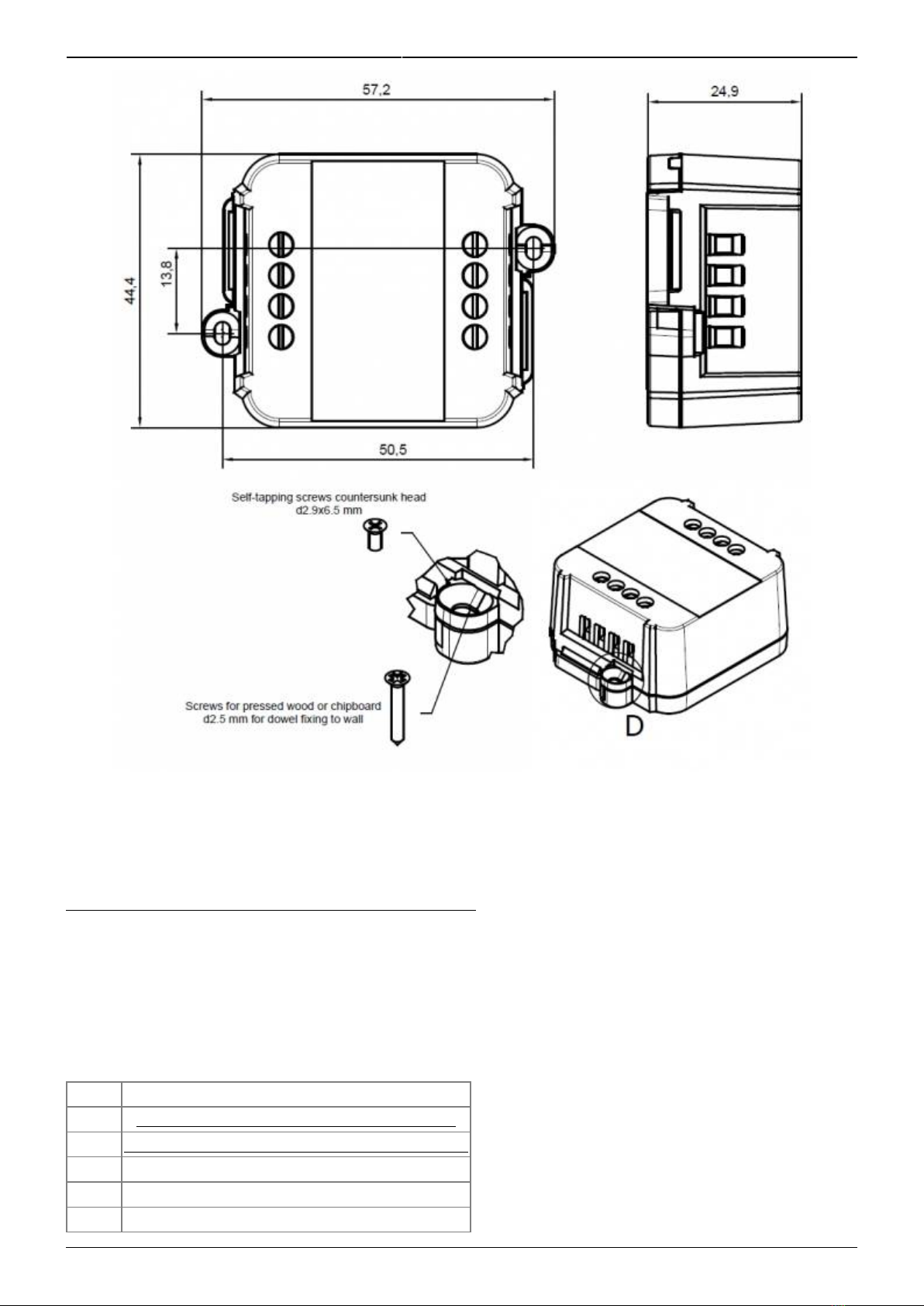
Dimension: 58x44x25mm
2022/08/30 06:23 3/19 manual_mcf-lw13io
e n g i n k o . s u p p o r t . c e n t e r - https://www.enginko.com/support/
2.2 Installation
The installation has to be done by a qualified electrician.
The device is intended as subassembly (component).
It is responsibility of the assembler of equipment incorporating to ensure that the overall equipment is
safe.
The MCF-LW13IO must be mounted in vertical position.
Please refer to following connections:
Name Description
L LINE Device power supply: 110÷230Vac~ Live
N LINE Device power supply: 110÷230Vac~ Neutral
L IN Digital Input monitor: 110÷230Vac~ Live
N IN Digital Input monitor: 110÷230Vac~ Neutral
C Terminal for Common contact

Last update: 2022/01/25 10:24 manual_mcf-lw13io https://www.enginko.com/support/doku.php?id=manual_mcf-lw13io&rev=1643102686
https://www.enginko.com/support/ Printed on 2022/08/30 06:23
Name Description
NC Terminal for Normally Close contact
NO Terminal for Normally Open contact
Caution: NIN and NLINE are internally connected.
The device must be placed where the LoRaWAN® signal coverage is good (SF = 7 optimal, SF = 12
weak).
2.3 Power supply
Connect the power supply to pins L LINE and N LINE. Valid range is 100Vac~ to 240Vac~ 50/60Hz.
2.4 Configuration
To deploy the sensor, download the latest LoRa Tool Android App to setup LoRaWAN® credentials
and other preferences :

2022/08/30 06:23 5/19 manual_mcf-lw13io
e n g i n k o . s u p p o r t . c e n t e r - https://www.enginko.com/support/
Move the NFC antenna of the mobile (the exact position varies depending on the model of the
smartphone) to the sensor antenna, in the area shown in the figure:
To use the NFC interface, the device must be powered through terminals L LINE and N LINE. The
power status is visible on the red/green led.
Always validate your settings by reading the NFC data after the sensor has restarted.
Configuration can be done only via NFC. No USB port available.
2.5 System leds
LoRaWAN® not configured Slow flashing
Joining Quick flashing
Sending Quick flashing
Receiving Quick flashing
Steady state Fixed
Data error Flashing 2 seconds
Connection error Flashing 1 second
Last update: 2022/01/25 10:24 manual_mcf-lw13io https://www.enginko.com/support/doku.php?id=manual_mcf-lw13io&rev=1643102686
https://www.enginko.com/support/ Printed on 2022/08/30 06:23
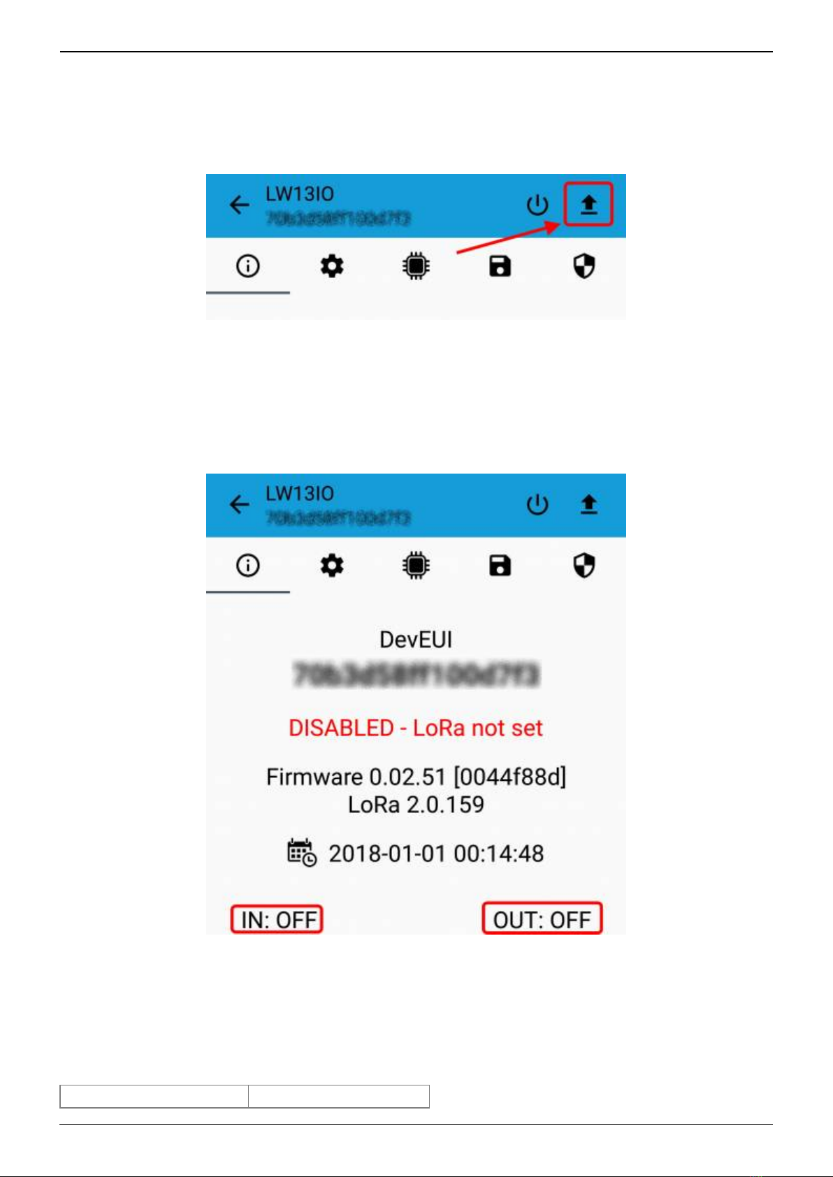
2.6 Firmware update
Save the firmware file (.FW) on the smartphone, and upload it with LoraTool App:
During the update, do not move the smartphone untill the end message.
3 I/O
As default, the device sends a message every time an input or an output changes.
A downlink with new output status forces the device to send back an unplink with the new status. If
the output status is the same of current one, the sensor will not send back any message.
Downlink examples (hex):
turn ON the output: 04000100000000000000

2022/08/30 06:23 7/19 manual_mcf-lw13io
e n g i n k o . s u p p o r t . c e n t e r - https://www.enginko.com/support/
turn off the output: 04000000000001000000
receive the current status: 04000000000000000000
Is possible to set a period (in minutes) to receive a recurrent periodic message with the I/O status.
3.1 Input
Off voltage 0÷2Vac 50/60Hz
On Voltage > 8Vac 50/60Hz
Maximum input voltage 250Vac 50/60Hz
Input current 3mA typ
Max frequency (as counter) 2 Hz
Optoinsulation NONE
Caution: NIN and NLINE are internally connected.
Input can be used as pulse counters (see seetings chapter).
3.2 Output
Contact mode SPDT
Max. power commutable 2000VA
Maximum switching voltage 250Vac~
Max. current 8A
Last update: 2022/01/25 10:24 manual_mcf-lw13io https://www.enginko.com/support/doku.php?id=manual_mcf-lw13io&rev=1643102686
https://www.enginko.com/support/ Printed on 2022/08/30 06:23
The output has pulse capability (minimum pulse duration is 100ms, maximum around 100 minutes),
so, instead to send two different commands (one to turn on and one to turn off the ouput), is possible
to send a duration command.
As application example, to safely turn on an output, send a ON-pulse command for a defined time (for
example, for the maximum allowed interval), and before the expiring time, another ON-pulse
command (making a kind of watchdog) if the output still needs to be ON, or a simply OFF command if
you want to turn it off.
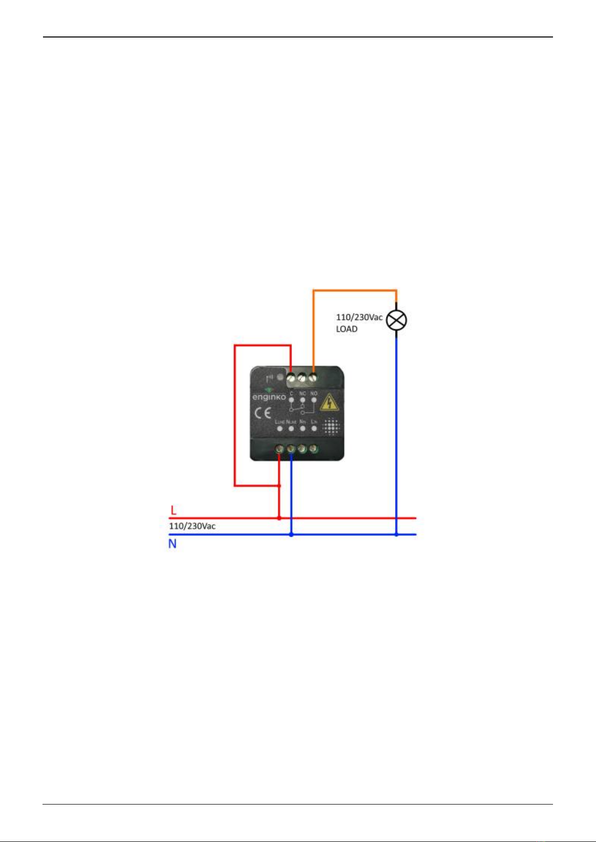
3.3 Wiring examples
Load connected to the same supply of the sensor, connected to the relay output (normally open
contact):
Load connected to an auxiliary power supply (AC or DC), connected to the relay output (normally
open contact), and a switch connected the digital input :

2022/08/30 06:23 9/19 manual_mcf-lw13io
e n g i n k o . s u p p o r t . c e n t e r - https://www.enginko.com/support/
}}
4 LoRaWAN® network
The sensor is compliant with LoRaWAN® specification 1.0.2, regional 1.0.2b.

Last update: 2022/01/25 10:24 manual_mcf-lw13io https://www.enginko.com/support/doku.php?id=manual_mcf-lw13io&rev=1643102686
https://www.enginko.com/support/ Printed on 2022/08/30 06:23
4.1 Activation
The device supports the following activations on a LoRaWAN® network:
NONE: sensor not activated1.
OTAA: the JoinEUI and the AppKey not setted, must be written to the device;2.
OTAA MCF88: Over the air activation, fixed keys: JoinEUI = 904e915000000003, AppKey on3.
request;
OTAA ENGINKO: Over the air activation, fixed keys: JoinEUI = 904e915000000003, AppKey on4.
request;
ABP: requires writing to the device of NwkSkey, AppSkey, DevAddr.5.
The device exits factory activated with NONE mode. On request devices can be shipped aleady
activated.
Note: in OTAA AppKey is write only, in reading the field will always be empty, even if set.
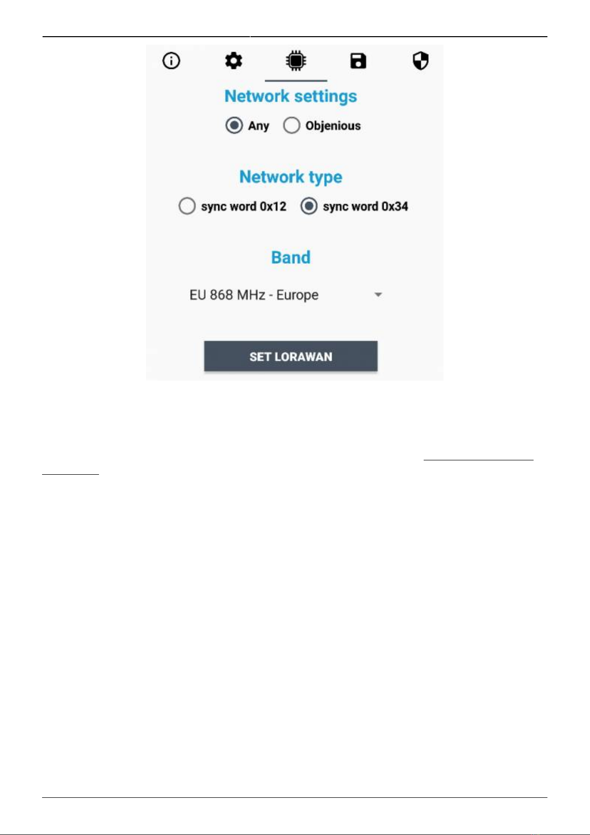
4.2 Other settings
2022/08/30 06:23 11/19 manual_mcf-lw13io
e n g i n k o . s u p p o r t . c e n t e r - https://www.enginko.com/support/
Network settings:
please keep “Any” settings. Change it only if Objenious network is used (default_ any).
Network type:
LoRa syncword can be setted as “private”(0x12) instead “public” (0x34), but the NS must be setted
accordingly (default: public).
Band:
select the right LoRaWAN ® band settings accodingly to country requirements.
Last update: 2022/01/25 10:24 manual_mcf-lw13io https://www.enginko.com/support/doku.php?id=manual_mcf-lw13io&rev=1643102686
https://www.enginko.com/support/ Printed on 2022/08/30 06:23
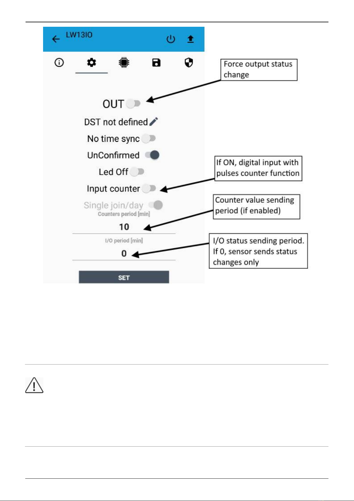
OUT:
set to force a change of the output (default: off).
DST:
set to change DST (default: none).
No time sync:
set to disable time synchronization request (default: enabled).
Normally sensor asks for a time sync at every power on (uplink starting with 01) or, if enabled, once a
week.
Please check chapter 2.1 of “DATA FRAME FORMAT” document.
UnConfirmed:

2022/08/30 06:23 13/19 manual_mcf-lw13io
e n g i n k o . s u p p o r t . c e n t e r - https://www.enginko.com/support/
set for unconfirmed uplinks (default: confirmed uplink).
Led Off:
set to disable the system leds (default: enabled).
Input counter:
set to enable the pulses counter funcion (default: disabled).
Single join/day:
set for to allow only one join per day (default: multiple join allowed).
Counters period [min]:
if counter enabled, this is the interval (in minutes) between one measure and the next one. The
sensor sends one measures for every transmission. Value can be between 1 and 255 minutes
(default: 0 minutes). Period interval can be set with App or with downlink command.
I/O period [min]:
if different from 0, this is the interval (in minutes) between one I/O messages status and the next one.
Value can be between 1 and 255 minutes (default: 0 minutes - disabled). Period interval can be set
with App or with downlink command.
5 Passwords
The device can be protected by passwords, to avoid unauthorized persons to read data or modify
parameters.
As default passwords are equal to 0.
Allowed values range from 0 to 999999999 (only numbers).
To change the passwords, set the new values with the LoRa Tool App:

Last update: 2022/01/25 10:24 manual_mcf-lw13io https://www.enginko.com/support/doku.php?id=manual_mcf-lw13io&rev=1643102686
https://www.enginko.com/support/ Printed on 2022/08/30 06:23
Once the passwords are setted, to gain access from LoRa Tool to the sensor, open the App:
and set the right values before reading from the device:

2022/08/30 06:23 15/19 manual_mcf-lw13io
e n g i n k o . s u p p o r t . c e n t e r - https://www.enginko.com/support/
To bring back the sensor to factory default and reset the passwords, a reset code must be requested
to enginko (please provide the DevEUI of the sensor when you ask for that code).
6 Configuration file
WIth LoRa Tool App is possible to configure the device using an XML file, instead to manually adjust
the parameters (for details about the file format please ask to enginko). This is very useful especially
in case of multiple devices configuration.
With “Save” button an XML file with the actual configuration of the sensor will be generated. This is
useful to store or clone the configuration, or to send it to enginko's support if needed.

Last update: 2022/01/25 10:24 manual_mcf-lw13io https://www.enginko.com/support/doku.php?id=manual_mcf-lw13io&rev=1643102686
https://www.enginko.com/support/ Printed on 2022/08/30 06:23
6.1 Multi devices configuration
WIth LoRa Tool App is possible to configure many devices in an easy way.
For multi-configuration is needed at least one XML file with the parameters to set.
Settings on this file will be applied to all the sensors.
With an additional XLS file is possible to load different LoRa configuration parameters (Activation
Type, AppKey, AppEUI, NetKey, DevAddress, Band, Private option) for each sensor, based on DevEUI.
When the sensor is approached, if one parameter is different from files, the APP will ask you if you
want to overwrite.
XLS is prevailing on the XML, so if both files are enabled, if the DevEUI of the device matches one of
the DevEUIS is in the XLS file, LoRa parameters will be setted from this one.
These configuration can be done in the in the Settings:
Enable or disable the use of the general configuration by file;
Enable or disable the use of the specific configuration by file;
Verify the passwords;
Writing the passwords.

2022/08/30 06:23 17/19 manual_mcf-lw13io
e n g i n k o . s u p p o r t . c e n t e r - https://www.enginko.com/support/
For details on files format please ask to enginko.
7 LoRaWEB Tool
enginko provides, upon free registration, LoRaWEB online tool, where for each sensor it is possible to
find documentation, javascript examples for parsing, downlink generator and uplink decoder:
LoRaWEB Tool (iot.mcf88.cloud/LoRaWeb)

Last update: 2022/01/25 10:24 manual_mcf-lw13io https://www.enginko.com/support/doku.php?id=manual_mcf-lw13io&rev=1643102686
https://www.enginko.com/support/ Printed on 2022/08/30 06:23
8 Payload
For payload descriptions, uplinks and downlinks format and available commands please refer to this
document:
DATA FRAME FORMAT
9 Ordering code
Code Description
MCF-LW13IO enginko LoRaWAN® wireless actuator EU863-870
MCF-LW13IO-AS enginko LoRaWAN® wireless actuator AS920-925
MCF-LW13IO-US enginko LoRaWAN® wireless actuator US902-928
MCF-LW13IO-AU enginko LoRaWAN® wireless actuator AU915-928
10 Declaration of conformity
Hereby, enginko Srl declares that MCF-LW13IO complies with the essential requirements and other
relevant provisions of Directive 2014/53/EU.
11 FCC compliance for MCF-LW13IO-US
This device complies with part 15 of the FCC Rules. Operation is subject to the following two
conditions: (1) This device may not cause harmful interference, and (2) this device must accept any
interference received, including interference that may cause undesired operation.
This equipment has been tested and found to comply with the limits for a Class B digital device,
pursuant to part 15 of the FCC Rules. These limits are designed to provide reasonable protection
against harmful interference in a residential installation. This equipment generates, uses and can
radiate radio frequency energy and, if not installed and used in accordance with the instructions, may
cause harmful interference to radio communications. However, there is no guarantee that
interference will not occur in a particular installation. If this equipment does cause harmful
interference to radio or television reception, which can be determined by turning the equipment off
and on, the user is encouraged to try to correct the interference by one or more of the following
measures:
Reorient or relocate the receiving antenna.
Increase the separation between the equipment and receiver.
Connect the equipment into an outlet on a circuit different from that to which the receiver is
connected.
Consult the dealer or an experienced radio/TV technician for help.
Any changes or modifications not expressly approved by the party responsible for compliance could
void the user’s authority to operate this equipment.
Contains FCC ID: 2AWAL409810
Table of contents
Popular Door Opening System manuals by other brands


Quantek
Quantek pilot Series Mounting and operating instructions

Carlisle Brass
Carlisle Brass CDG003 installation instructions

Tormax Automatic
Tormax Automatic Win Drive 2201 Instructions for use

Record
Record DFA 127 instructions

CAMDEN
CAMDEN CM-SRFM2 Kit installation instructions

DITEC
DITEC NRG100TXE Technical manual


