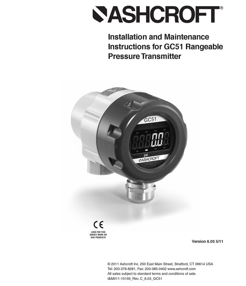
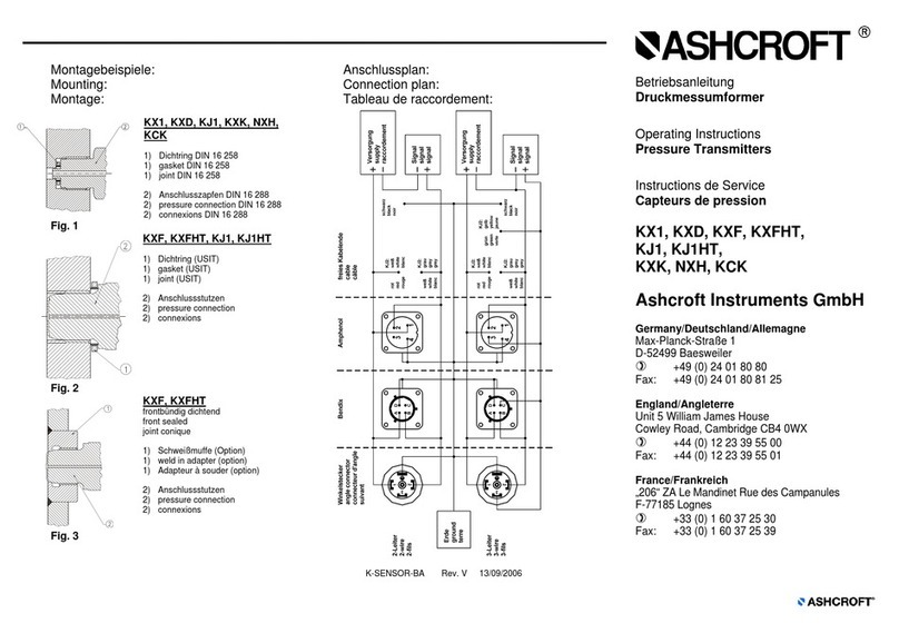
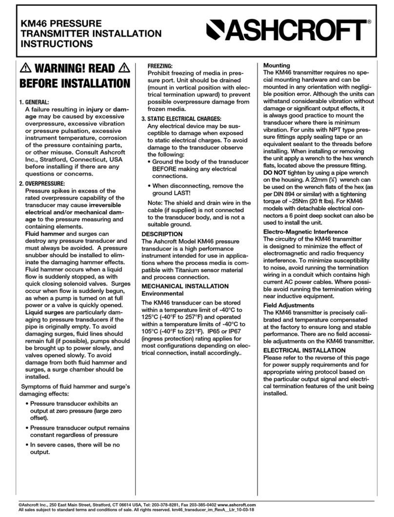
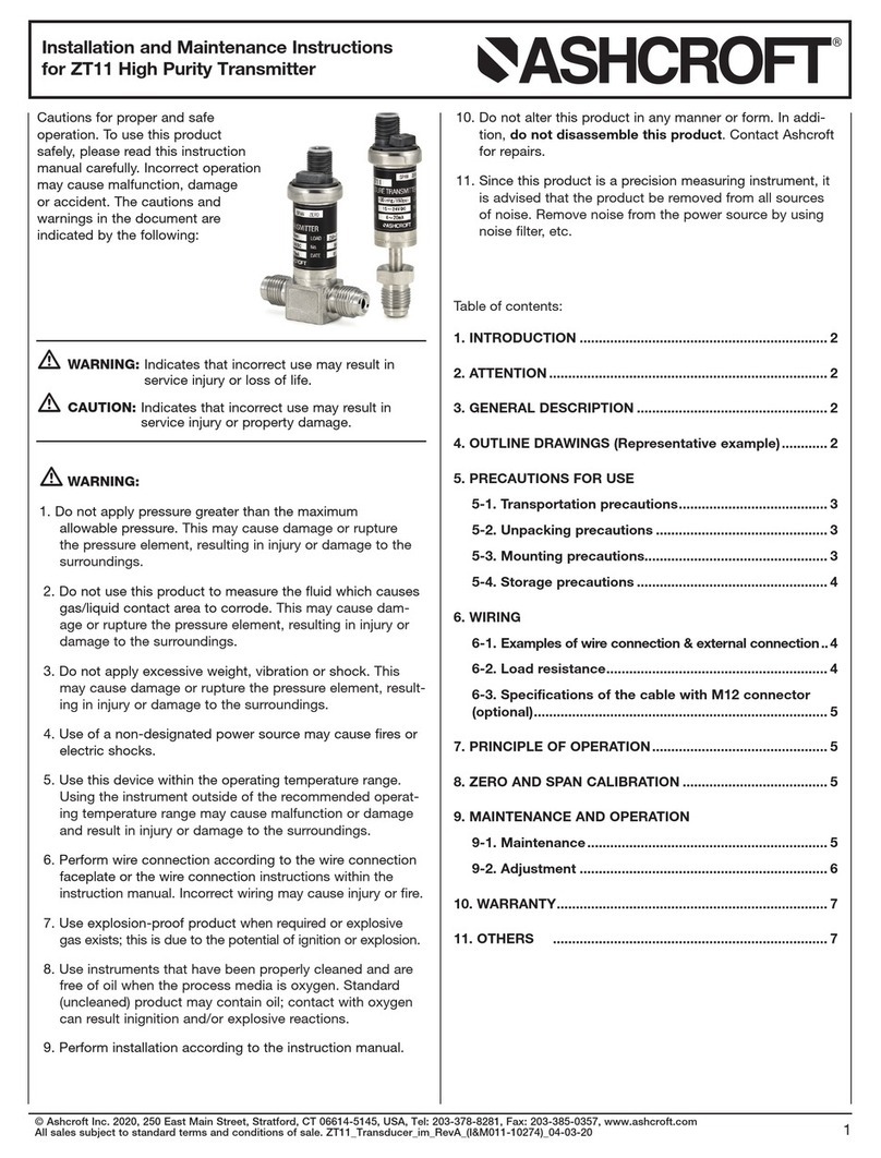
Ashcroft GC52 User manual

Product Information Page
All specifications are subject to change without notice.
All sales subject to standard terms and conditions.
© 2017 Ashcroft Inc.
ashcroft.com
info@ ashcroft.com
1.800.328.8258
Rev. A 02/17, Page 1 of 8
PIP #: TR-PI-102
Applicable to:
GC52
PROGRAMMING USER DEFINED FLOW RATE UNITS ON THE GC52
DIFFERENCIALPRESSURE TRANSMITTER
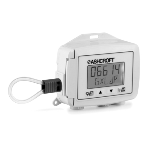
The GC52 differential pressure transmitter is compact and flexible
instrument often used in flow measurements and volume applications. It
can be easily programmed with user defined units to display flow rate in
Gallons Per Minute (GPM) and volume in gallons.
Figure 1 –GC52 Differential Pressure Transducer
Water Flow Rate and Volume Application:
This example demonstrates the use of GC52 differential pressure transmitter to measure and control
flow rate in GPM. Also, to switch from flow rate reading to volume, automatic or manual. Although, the
GC52 differential pressure transmitter can be purchase with several ranges, for this application a
transmitter with 0 to 40 IWC pressure range has been selected. As well, an orifice plate with 2.40” bore,
an eight-inch line diameter pipe and a variable frequency water pump. The transmitter shall provide the
analog output to the variable frequency water pump. The variable frequency water pump uses the 4-
20mA input to control the amount of energy sent to the pump to slow down or speed up the pump to
maintain a constant flow of 65 GPM.

Product Information Page
All specifications are subject to change without notice.
All sales subject to standard terms and conditions.
© 2017 Ashcroft Inc.
ashcroft.com
info@ ashcroft.com
1.800.328.8258
Rev. A 02/17, Page 2 of 8
Figure 2 - GC52 Flow Rate Diagram Example Figure 3 - GC52 Installation Example
Installation:
Remove the lid from the transmitter by turning it counter clockwise to expose electrical terminal block.
Wire transmitter per manual instructions, and see diagram below for reference.
Figure 4 - GC52 Wiring Diagram

Product Information Page
All specifications are subject to change without notice.
All sales subject to standard terms and conditions.
© 2017 Ashcroft Inc.
ashcroft.com
info@ ashcroft.com
1.800.328.8258
Rev. A 02/17, Page 3 of 8
Principles of Operation and Program Instructions:
Flow rate is calculated by using Bernoulli’s equation below by measuring the differential pressure across
an orifice plate. The GC52 will be using the orifice plate manufacturer’s data of maximum flow rate with
corresponding differential pressure drop.
𝑄= 𝐾√∆𝑃
𝜌
𝐾= 𝑐𝑜𝑒𝑓𝑓𝑖𝑐𝑖𝑒𝑛𝑡
∆𝑃= 𝐷𝑖𝑓𝑓𝑒𝑟𝑒𝑛𝑡𝑎𝑖𝑙 𝑃𝑟𝑒𝑠𝑠𝑢𝑟𝑒
𝜌= 𝐷𝑒𝑛𝑠𝑖𝑡𝑦
𝑄= 𝐹𝑙𝑜𝑤 𝑟𝑎𝑡𝑒
Manufacturer orifice plate specifications:
𝐿𝑖𝑛𝑒 𝑆𝑖𝑧𝑒 = 8” 𝑑𝑖𝑎𝑚𝑒𝑡𝑒𝑟
𝐵𝑜𝑟𝑒 = 2.4” 𝑏𝑜𝑟𝑒
𝑀𝑎𝑥𝑖𝑚𝑢𝑚 𝐹𝑙𝑜𝑤 = 88 𝐺𝑃𝑀 @ 20 𝐼 𝑊𝐶
GC52 Differential Pressure Transducer Flow and integrated Volume Program Guidelines:
Below is an Illustration to program the transmitter in GPM and integrated volume in gallons as the
arbitrary units. Proceed to scale down the transducer range from 40 IWC to 20 IWC. That, is the
maximum differential pressure equivalent to 88 GPM of water (20 mA). Follow the steps below to
rescale and program the transmitter from 0 to 20 IWC of water equivalent to the arbitrary units of 0 to
88 GPM.
Remove Access Cover to Expose MODE, UP and DOWN Buttons
Press and hold M button for more than three seconds to get into program
mode.
Press UP or Down arrow to make changes.
Press and release M button to select changes and to walk through the menu.
Continue to step-1 after power-on message.
Press and hold M button anytime for more than three seconds to return to
measuring mode.

Product Information Page
All specifications are subject to change without notice.
All sales subject to standard terms and conditions.
© 2017 Ashcroft Inc.
ashcroft.com
info@ ashcroft.com
1.800.328.8258
Rev. A 02/17, Page 4 of 8
F0To enter filter selection (selections of 0,2,4,8, and 16 times).
The filter function is used when pressure fluctuates to improve
analog output and difficult to read display.
Select the factory default filter F0. Since pressure fluctuation is not
expected.
Press and release M button to select and move to the next step.
Step
2
nrot To enter configuration mode. There are three pressure modes,
linear, non-linear, and square root function.
Select square root function to convert pressure into flow rate and to
use arbitrary units.
Press UP or Down arrow to display “n rot”.
Press and release M button to select and move to the next step.
Step
3
P 20.0 To enter the maximum differential pressure corresponding
to the maximum flow rate (88 GPM).
This is the orifice plate specification value.
Press Up or Down arrow until 20.0 is displayed. That, is the
maximum differential pressure corresponding to 88 GPM of water.
Press and release M button to select and move to the next step.
Step
4
d1To select the decimal point position. There are four decimal
point selections (0,1, 2, and 3 digits).
Press Up or Down arrow until 1 is display. For this application one
digit after decimal point shall be used.
Press and release M button to select and move to the next step.
Step
5
_ _ _ _
d 88.0 To enter the maximum arbitrary units 88 GPM of water
corresponding to differential pressure of 20 IWC.
Press Up or Down arrow until 88.0 is selected. That, is the 88 GPM of
water corresponding to 20 IWC.
Press and release M button to select and move to the next step.

Product Information Page
All specifications are subject to change without notice.
All sales subject to standard terms and conditions.
© 2017 Ashcroft Inc.
ashcroft.com
info@ ashcroft.com
1.800.328.8258
Rev. A 02/17, Page 5 of 8
Step
6
L0.0 To enter low-cut to flow rate. It forces display to zero and
analog output to 4 mA.
Low-cut shall not be used on this application, constant flow rate
shall be maintained.
Press Up or Down arrow until 0.0 is selected.
Press and release M button to select and move to the next step.
Step
7
A 0.0 To enter analog output zero reference corresponding to 4
mA.
The operational range is from 0 to 88 GPM of water. Therefore,
select 0% FS or 4mA analog output.
Press Up or Down arrow until 0.0 is displayed. That, is the analog
output at 0% FS (4mA at 0 GPM of water).
Press and release M button to select and move to the next step
Step
8
_ _ _ _
A 100.0 To enter span analog output reference corresponding to 20
mA.
The operational range is from 0 to 88 GPM of water. Therefore,
100% full span is selected as the span or 20 mA analog output.
Press UP or Down arrow until 100.0 is displayed. That, is the analog
output at 100% FS (20mA at 88 GPM).
Press and release M button to select and move to the next step.
Step
9
Unin To enter time factor. When flow rate is GPM, minutes shall
be selected as the same time factor.
Press UP or Down arrow until “n in” is displayed. That, is the time
factor corresponding to minutes.
Press and release M button to select and move to the next step.
Step
10
U _ _ 1 To enter Flow rate volume factor. When flow rate is GPM, 1
shall be selected to match flow factor units of gallons X1.
Selectable options 1,10, 100 and 1000.
1 shall be selected since the arbitrary units are in gallons.
Press UP or Down arrow until “1” is displayed. That, is the unit factor
corresponding to gallons.
Press and release M button to select and move to the next step.

Product Information Page
All specifications are subject to change without notice.
All sales subject to standard terms and conditions.
© 2017 Ashcroft Inc.
ashcroft.com
info@ ashcroft.com
1.800.328.8258
Rev. A 02/17, Page 6 of 8
Step
11
Sbt To enter switch mode of momentary flow rate and integrated
volume. There is manual mode (bt) or automatic mode (ti).
For this application manual switch mode shall be selected.
It only displays integrated volume when cover is removed and M
button is pressed. Otherwise it only displays flow rate.
Automatic setting time is selectable from 1 to 10 seconds cycle.
Press UP or Down arrow until “bt” is displayed.
Press and release M button to select and move to the next step.
Step
12
C 0.0 Loop check mode allows program and analog output
verification with the transmitter pressurized or non-pressurized. It
simulates the process and allows for troubleshooting.
Press Up or Down arrow to change within transmitter range (0 to 88
GPM of water).
Press and release M button to return to the begin of program
After verification press and hold M button for more three seconds to
return to measuring mode.
Function Verification:
The GC52 loop-check allows to verify program and analog output with the transmitter pressurized or
non-pressurized.
Once Step-11 is reached, the unit is in Loop-
check mode. The system can be verified by
increasing or decreasing the flow rate value (0 to
88 GPM of water).
Use the Up or down arrow and observe the
display segments get brighter as the flow rate
value increases. That, is an indication that the
analog output and wiring are reacting properly.

Product Information Page
All specifications are subject to change without notice.
All sales subject to standard terms and conditions.
© 2017 Ashcroft Inc.
ashcroft.com
info@ ashcroft.com
1.800.328.8258
Rev. A 02/17, Page 7 of 8
Analog output terminal check:
When the front cover is removed, the analog output check terminals CH+ and CH–are visible at the
upper part of the display. The analog output can be checked during measurement mode or loop check
(see figure 4 below for reference).
Figure 4 - Analog Output Verification
C 44.0

Product Information Page
All specifications are subject to change without notice.
All sales subject to standard terms and conditions.
© 2017 Ashcroft Inc.
ashcroft.com
info@ ashcroft.com
1.800.328.8258
Rev. A 02/17, Page 8 of 8
Analog output check:
Similarly, analog output can be verified by placing an amp-meter in series with the transmitter output
and power supply (see manual wiring instructions for reference). As well, during measurement mode or
loop check (see results below for reference).
Connect amp meter per manual
instructions or figure above.
Press the Down arrow until 0.0 GPM is
displayed or apply 0 IWC.
Verify amp meter reading (4.00 mA).
0.0 GPM of water corresponds to 0% FS (4
mA at 0.0 GPM of water).
Press the Up or Down arrow until 44.0 GPM
is displayed or apply 10 IWC.
Verify amp meter reading (12.00 mA).
44.0 GPM of water corresponds to 50% FS
(12 mA at 44.0 GPM of water).
Press the Up arrow until 88.0 GPM is
displayed or apply 20.0 IWC.
Verify amp meter reading (20.0 mA).
88.0 GPM of water corresponds to 100% FS
(20 mA at 88.0 GPM of water).
Other manuals for GC52
1
Table of contents
Other Ashcroft Transmitter manuals

Ashcroft
Ashcroft KX1 User manual

Ashcroft
Ashcroft KM41 User manual

Ashcroft
Ashcroft km46 User manual

Ashcroft
Ashcroft GC52 Instruction Manual

Ashcroft
Ashcroft ZT12 User manual
Ashcroft
Ashcroft km11 User manual

Ashcroft
Ashcroft ZT11 User manual

Ashcroft
Ashcroft GC51 User manual

Ashcroft
Ashcroft XLDP1 User manual

Ashcroft
Ashcroft G2 User manual
Popular Transmitter manuals by other brands

Chungear Industrial
Chungear Industrial TR293A Operation and installation instructions

evertz
evertz 7700 MultiFrame manual

Novus
Novus RHT-WM instruction manual

INOR
INOR IPAQ C520 Handbook & User Manual

Vaisala
Vaisala HMP260 SERIES operating manual

Becker
Becker Centronic EasyControl EC242-II Assembly and operating instructions