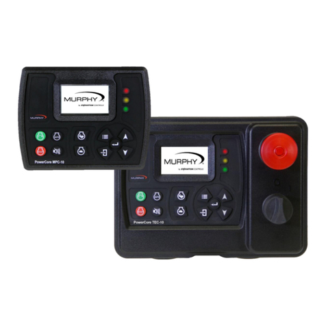
Enovation Controls MURPHY PowerCore MPC-20-R2 User manual

Software Release: [App: 02.09.10039.00; Config: 2.9.20024; Built in PowerVision Configuration Studio Version:
2.9.23042; BTL: 02.09.10015.00]
00-02-0996
2019-06-13
Section 40
PowerCore®
MPC-20-R2 Engine Controller
Operations Manual
*Approved by CSA for non-hazardous locations (Group Safety Publication EIC 61010-1, Third Edition)
Products covered in this document comply with European Council electromagnetic compatibility directive
2014/30/EU and electrical safety directive 2014/35/EU.

Software Release: [App: 02.09.10039.00; Config: 2.9.20024; Built in PowerVision Configuration Studio Version:
2.9.23042; BTL: 02.09.10015.00]
Section 40 00-02-0996
2019-06-13 - ii -
In order to consistently bring you the highest quality, full-featured products, we reserve the right to
change our specifications and designs at any time.
ENOVATION CONTROLS has made efforts to ensure the reliability of the MPC-20 and
to recommend safe use practices in system applications. Please note that in any
application, operation and controller failures can occur. These failures might result in full
control outputs or other outputs that might cause damage to or unsafe conditions in the
equipment or process connected to the MPC-20.
Good engineering practices, electrical codes and insurance regulations require that you
use independent external protective devices to prevent potentially dangerous or unsafe
conditions. Assume that the MPC-20-R2 can fail with outputs full ON, outputs full OFF
or that other unexpected conditions can occur.
Please read the following information before operating the MPC-20-R2:
•Observe all Warnings and Cautions in each section of these instructions.
•The MPC-20 is designed for use in industrial environments. There might be potential
difficulties in ensuring electromagnetic compatibility in other environments due to
conducted as well as radiated disturbances.
•Please contact ENOVATION CONTROLS immediately if you have any questions.
IMPORTANT! False or improper use and operation of electronic
products could be dangerous. It is required that point-of-operation
guarding devices be installed and maintained. All such devices
must meet OSHA and ANSI Machine safety standards. The
manufacturer shall not accept any responsibility for installation,
application or safety of systems.

Software Release: [App: 02.09.10039.00; Config: 2.9.20024; Built in PowerVision Configuration Studio Version:
2.9.23042; BTL: 02.09.10015.00]
Section 40 00-02-0996
2019-06-13 - iii -
The MPC-20 can be set as an Auto Start Controller. Please be cognizant at all times of hands and
other objects that are in close proximity to the machine(s) being controlled as they may commence
operation suddenly and without warning.
LENS CLEANING PROCEDURES
The lens on the MPC-20 is composed of
polycarbonate materials. Use only mild soap and
water to clean the lens/display window. Evidence
of improper cleaning techniques or chemicals
includes cracks, smear marks, scratches or
fogged/hazy lenses.

Software Release: [App: 02.09.10039.00; Config: 2.9.20024; Built in PowerVision Configuration Studio Version:
2.9.23042; BTL: 02.09.10015.00]
Section 40 00-02-0996
2019-06-13 - iv -
- THIS PAGE INTENTIONALLY LEFT BLANK -

Software Release: [App: 02.09.10039.00; Config: 2.9.20024; Built in PowerVision Configuration Studio Version:
2.9.23042; BTL: 02.09.10015.00]
Section 40 00-02-0996
2019-06-13 - v -
Table of Contents
Introduction................................................................................................................................7
Murphy PowerCore 20 Revision 2 (MPC-20-R2).........................................................7
User Interface..............................................................................................................9
Accessing the Menu................................................................................................................10
Main Menu ................................................................................................................................10
Auto Start/Stop Functions Defined.......................................................................................14
Single Contact Start/Stop...........................................................................................14
Local Start Key Start/Stop..........................................................................................14
Two Contact Maintained Start/Stop (commonly known as Floats).............................15
Two Contact Momentary Start/Stop...........................................................................15
(Pressure, Level, Flow or Temperature) Transducer Start/Stop ................................15
Auto Throttling Functions Defined .......................................................................................15
Running Loaded Throttle ...........................................................................................15
(Pressure, Level or Flow) Transducer Throttle...........................................................15
Local Throttle Input....................................................................................................15
Quick-Start Setup Guide.........................................................................................................15
Setting up for a Mechanical Engine ...........................................................................16
Setting up for an Electronic J1939 Engine.................................................................16
Adjusting Screen Contrast.........................................................................................17
Setting up to Auto Start/Stop for Single Contact Input (Single Float).........................17
Setting up to Auto Start/Stop for Start Local Key.......................................................17
Setting up to Auto Start/Stop for 2 Contact Inputs (Dual Floats)................................17
Setting up to Auto Start on Pressure .........................................................................18
Setting up to Auto Start on Level...............................................................................18
Setting up to Auto Start on Flow................................................................................19
Setting up to Auto Start on Clock...............................................................................19
Setting up to Auto Start on Temperature ...................................................................19
Setting up to Stop the Engine from Utilizing the Countdown Timer ...........................20
Screen Examples.....................................................................................................................21

Software Release: [App: 02.09.10039.00; Config: 2.9.20024; Built in PowerVision Configuration Studio Version:
2.9.23042; BTL: 02.09.10015.00]
Section 40 00-02-0996
2019-06-13 - vi -
Additional Screens.....................................................................................................21
Warning and Shut-Down Icons..................................................................................26
Icon Troubleshooting .................................................................................................28
Menu Glossary......................................................................................................................... 28
System (Low Security)...............................................................................................28
Engine Settings (Low Security)..................................................................................30
Advanced Engine Settings (Low Security).................................................................32
Throttle Menu (Medium Security)...............................................................................37
Input / Output Menu (Medium Security).....................................................................38
Application Configuration (Medium Security).............................................................43
Start / Stop Timers (Low Security).............................................................................48
Communication (High Security) .................................................................................49
Passcodes (High Security).........................................................................................50
Load Configuration (High Security)............................................................................50
Communications..................................................................................................................... 51
Modbus Registers......................................................................................................51
CAN Parameter Map..................................................................................................51
Supplementary Information................................................................................................... 60
Passcodes.................................................................................................................60
PC Configuration Software ........................................................................................61
Specifications.......................................................................................................................... 62

Software Release: [App: 02.09.10039.00; Config: 2.9.20024; Built in PowerVision Configuration Studio Version:
2.9.23042; BTL: 02.09.10015.00]
Section 40 7 00-02-0996
2019-06-13
Introduction
This document is designed to familiarize a user withthe MPC-20-R2 and explain how to navigate the interface
and modify the settings when installing/operating the controller. The Quick Set Up guide assists with
establishing the different functions in the MPC-20-R2 for system setup. Before attempting to set up the
controller, be sure to read and understand this manual in its entirety.
Murphy PowerCore 20 Revision 2 (MPC-20-R2)
The Murphy PowerCore 20 Controller (MPC-20) is a general all-purpose manual/auto start and manual/auto
throttling engine controller. The controller is purposed primarily for pump and irrigation applications; however,
it is versatile and flexible enough to be used on many applications outside pump and irrigation. This is a
powerful controller that supports J1939 CAN protocols for electronically governed engines as well as
mechanical engines for fault and safety shutdowns.
The MPC-20-R2 is flexible in many aspects. The flexibility consists of the ability to:
•use in most applications where auto start or auto throttling is required or desired;
•use the same controller on electronically governed J1939 and mechanical engines;
•establish multi-level securities in the menu structure when using the configuration tool;
•use the same controller on 12VDC or 24VDC systems;
•use as auto start and/or manual start controller;
•use as manual throttle and/or auto throttle controller;
•change the input type for the analog inputs;
•use additional analog inputs as digital ground inputs;
•assign functions and actions to digital inputs;
•use digital inputs as battery or ground inputs;
•be mounted in all-weather environment;
•be customer-mounted in panel of choice.
Engine Application States and Delays
While reprogrammable, the MPC-20 follows a standard operating sequence. This operating sequence is a
set of machine states that happen in a predetermined order. Machine states and/or delays can be set to zero
if not needed or adjusted to fit the application. The following states and delays will be executed during the
auto sequence, provided that the corresponding timer has not been set to 00:00:00 or the controller has not
been placed in a manual mode of operation:
•Stabilize: a timedstate toallowthecontrollerto enabletheECUprior tothe controllercranking
the engine. This timer can be disabled if set up for mechanical engine use by changing the
ECU Stabilize Timer to 0.
•Stopped: a timed state where the controller is ready to start the engine manually or
automatically. This is also the state that allows changes to be saved in the Menu.
•Standby: a timed state that will shut off the LCD backlight, heater and CAN transceiver to
conserve battery power while the unit waits for a key press or an automatic start condition.
•Wait To Start: when an engine is not ready to start and sends a message across the J1939
communications stating it is not ready to start.
•Auto Start Delay: (available in Auto mode only) a user-defined timed state that ensures the
auto start signal is present for a desired amount of time prior to cranking the engine. During
this period, the auto start condition is ignored and must remain active throughout this delay, or
the delay is reset to zero.

Software Release: [App: 02.09.10039.00; Config: 2.9.20024; Built in PowerVision Configuration Studio Version:
2.9.23042; BTL: 02.09.10015.00]
Section 40 8 00-02-0996
2019-06-13
•Prestart Delay 1: (Auto Only or Auto/Manual) after a start condition has been accepted by
the controller, this delay begins timing, and the prestart output turns on. When this delay
expires, the output is turned off, and the auto sequence continues.
•Check Safe To Start: a non-timed state that will check to ensure the engine can start safely.
•Minimum Run Time: only active using auto start and with all auto start types except local key
and clock. Local stop key will also initiate the stop sequence before the timer expires, if
pressed.
•*Prestart Delay 2 (precrank): (Auto Only or Auto/Manual) after a start condition has been
accepted by the controller, this delay begins timing, and the prestart output turns on. When
this delay expires, the output is turned off, and the auto sequence continues. During this delay,
the controller checks for faults, J1939 com, etc.
•*Prestart Delay 2 (crank through): (Auto Only or Auto/Manual) after a start condition has
been accepted by the controller, this delay begins timing, and the prestart output turns on.
When this delay expires, the output remains on through crank. The output turns off when the
engine starts. During this delay, the controller checks for faults, J1939 com, etc.
•Crank: a timed state for when the controller turns on the Crank output to start the engine.
•Crank Rest: a timed state to rest the starter between cranks in case the engine did not start
during the crank state.
•False Start Check: a non-timed state that will ensure the engine stays above the crank cut
RPM after cranking.
•Warm-up: (available in Auto mode only) a timed state that will allow the engine to run at a
desired warm-up RPM after starting.
•Line Fill 1: (available in Auto mode only) a timed state that will allow the engine to run at a
desired Line Fill RPM and exit if the timer times out or the pressure set point for this state is
reached. This is commonly used when filling a discharge line to a desired pressure when a
lower RPM is needed prior to throttling to maintain a pressure.
•Line Fill 2: (available in Auto mode only) a timed state following Line Fill 1 that will allow the
engine to run at a desiredLine Fill RPM and exit if the timer times out or the pressure set point
for this state is reached. This is commonlyused when filling a HoseReel to a desired pressure
when a lower RPM is needed prior to throttling to maintain a pressure.
•Running Loaded: a non-timed state that the controller will stay in until a stop condition is
initiated in the controller.
•Auto Stop Delay: (available in Auto mode only) a user-defined timed state that ensures the
auto stop signal is present for a desired amount of time prior to entering the shutdown
sequence. During this period the auto stop condition is ignored and must remain active
throughout this delay, or the delay is reset to zero.
•Cooldown: (available in Auto mode only) a timed state that will allow the engine to run at a
desired speed to cool down before allowing to go into a stopped state.
•Energize to Stop: a timed state that will control an output in order to stop the engine. This
state will only work if the controller is shut down using an auto stop or the local stop key. If the
controller loses battery power, this state will not be initiated for energize to stop.
•Spindown:time allotted for the engine to stop all revolutions and be in a stopped state with
no frequency. The controller will repeat the Spindown state if the controller continues to get
RPM when the timer times out.

Software Release: [App: 02.09.10039.00; Config: 2.9.20024; Built in PowerVision Configuration Studio Version:
2.9.23042; BTL: 02.09.10015.00]
Section 40 9 00-02-0996
2019-06-13
User Interface
The keypad on the MPC-20-R2 is comprised of 11 tactile buttons. This section describes the functions of
each button.
The buttons have the following functions:
•Start Key –allows the operator to start sequence in Manual Mode or initiate an auto start
sequence when in Auto Mode.
•Stop Key –allows the operator to initiate the stop sequence in either mode of operation.
A single button press in auto will initiate an auto stop. As a safety feature, when the stop
button is pressed twice or held (in auto mode), the controller will skip the cool-down state
and (upon shutting down) will place itself in manual mode to eliminate an auto crank
condition if the start signal remains present.
•Auto Key –allows the operator to change from Auto to Manual or Manual to Auto Mode.
The MPC-20-R2 requires an acknowledgement from the user to place in auto mode from
manual.
•Alarm Silence Key –allows the operator to temporarily silence the internal siren, common
alarm output and acknowledge active faults when an alarm or shutdown is present on the
controller.
•Manual Throttle Increase Key –allows the operator to manually increase the engine
speed in Manual Mode.
•Manual Throttle Decrease Key –allows the operator to manually decrease the engine
speed in Manual Mode.
•Menu Key –allows the operator to get into and out of the menu.
•Back Key –allows the operator tomove back one step in themenu without saving a value.
•Enter Key –allows the operator to save a desired value or setting in the menu.
•Up Key –allows the operator to navigate up through the menu and page forward in the
main page views.
•Down Key –allows the operator to navigate down through the menu and page reverse on
the main page views.

Software Release: [App: 02.09.10039.00; Config: 2.9.20024; Built in PowerVision Configuration Studio Version:
2.9.23042; BTL: 02.09.10015.00]
Section 40 10 00-02-0996
2019-06-13
Accessing the Menu
The MPC-20-R2 has three menu security levels to restrict users from making changes after installation. The
security levels are Low, Medium and High. One may consider these security levels as user, technician and
OEM. The low level security only has a small number of items a user can access. The medium level security
has all the low level menu items plus others a technician may change while in the field. The high security level
has the entire menu visible to the user or OEM.
To access the menu, press the menu key. Review section Passcodes to understand the menu level preset in
the MPC-20-R2.The following screen will display to enter the passcode: [Low=1111; Medium=5311;
High=3482].
The passcode will be entered left to right. Utilize the up and down arrows, and press the Enter button after
each correct number. If you enter the wrong passcode, it will reset the display to 0000, allowing you to restart
the entry process.
Main Menu
The MPC-20 controller is incredibly versatile within its menu structure. The operator is able to change many
parameters and settings from the face without the need of a PC tool, if desired. The controller has to be in its
stopped state in order to save a setting in the menu. (The Tier 4 menu is the exception). Described below are
the main sections of the controller’s menu. Cycling power to the controller is recommended after making
changes to set points.
(Main Menu, page 1)

Software Release: [App: 02.09.10039.00; Config: 2.9.20024; Built in PowerVision Configuration Studio Version:
2.9.23042; BTL: 02.09.10015.00]
Section 40 11 00-02-0996
2019-06-13
System
The controller System menu provides the operator with the ability to set the Date/Time, Units, Language,
Brightness, Contrast, Service Reminders and several other system settings. Review System under the Menu
Glossary section of this manual for a full list and definition of each setting.
Engine Settings
The Engine Settings menu allows the operator to establish common user-configurable parameters that would
be changed from factory-default settings when pairing the controller to an engine. This menu allows the
operator to choose whether the engine is J1939 or Mechanical; the engine’s speed source; the minimum and
maximum RPM the operator requires/allows the engine to run; the RPM step size; warm-up/cool-down
settings; and other common engine settings. Review Engine Settings under the Menu Glossary section of this
manual for a full list and definition of each setting.
Advanced Engine Settings
The Advanced Engine Settings menu allows the operator to set up the less common user-configurable
parameters that are notin the EngineSettings menuand which would bechanged from factory-default settings
when pairing the controllerto an engine. Thismenu allows the operator to set items such as the J1939 address
claim for the controller, ECU Source Address, ECU hour select, crank attempts, crank disconnect speed,
clutch engage/disengage speed, run to destruct mode and other user-specific engine settings. Review
Advanced Engine Settings under the Menu Glossary section of this manual for a full list and definition of each
setting.
Throttle
The Throttle menu allows the operator to set up the items for throttling the engine such as throttle type, rate
of RPM increase/decrease, throttle Inc/Dec pulse time, throttle RPM deadband and other parameters
pertaining to throttling of the engine. Review Throttle under the Menu Glossary section of this manual for a
full list and definition of each setting.
Input / Output
The Input/Output Menu allows the user to establish the I/O needed for the application. This includes Digital
Inputs, Analog Inputs, Relay Outputs and Digital Outputs. This menu is tied to other aspects of the controller
menu such as Auto Start Functions, Auto Throttling Methods, Analog inputs for Mechanical Engine setup,
Warning / Shutdown functions and all outputs needed for starting/controlling the engine and alerting the user.
The Digital Inputs of this menu can be configured from the face of the controller to accept three types of
inputs to trigger an action.
•B(+), High
•B(-), Low
•Open
The Analog Inputs of this menu can be configured from the face of the controller to accept one of four
types of sensors by software selection only.
•Resistive
•4-20mA
•0-5VDC
•B(-) for additional Digital Inputs

Software Release: [App: 02.09.10039.00; Config: 2.9.20024; Built in PowerVision Configuration Studio Version:
2.9.23042; BTL: 02.09.10015.00]
Section 40 12 00-02-0996
2019-06-13
The Outputs are configurable for the operator to choose which output function to use with the desired
output type as shown below.
•Relay [10A] Form C
•Digital Out [5V, 200mA]
•Digital Out [B+, 2A]
•Digital Out [B-, 1A]
•Analog Out [0-5VDC] Dedicated for analog throttling
NOTE: Although the functionality exists to set all analog and digital inputs to the same
function, Enovation Controls strongly advises against this.
(Main Menu, page 2)
Application Configuration
The Application Configuration menu is where an operator will set up the controller’s Auto Start Functions and
Auto Throttle Methods, if the intended use is an auto start and/or auto throttling controller. Depending on which
application is chosen in the menu, there are certain auto start functions and auto throttling methods hidden
that are not pertinent to the application chosen. This automatic hiding feature allows for a simpler, more
intuitive controller menu in the MPC-20.Review Application Configuration under the Menu Glossary section
of this manual for the full list and definition of each setting.
Pump All Purpose
The Pump All Purpose application houses most of the auto start functions and auto throttling methods
in the controller. This application is the most versatile application thus requiring so many combinations
of settings for the operator to choose.
The auto start functions and auto throttle methods to choose from are listed below.
Auto Start/Stop Functions
•Local Key Start
•Single Contact
•Two Contact Maintained
•Two Contact Momentary
•Pressure Transducer
•Level Transducer
•Flow Transducer
Auto Throttle Methods
•Running Loaded

Software Release: [App: 02.09.10039.00; Config: 2.9.20024; Built in PowerVision Configuration Studio Version:
2.9.23042; BTL: 02.09.10015.00]
Section 40 13 00-02-0996
2019-06-13
•Pressure Transducer
•Level Transducer
•Flow Transducer
•Local Throttle Input
Center Pivot / Linear Irrigation
The Center Pivot / Linear Irrigation application houses the auto start functions and auto throttle
methods meant to be used on center pivot and linear movement irrigation applications.
The auto start functions and auto throttle methods to choose from are listed below.
Auto Start/Stop Functions
•Single Contact
•Local Start Key
•Two Contact Maintained
•Two Contact Momentary
Auto Throttle Methods
•Running Loaded
•Pressure Transducer
•Flow Transducer
•Local Throttle Input
Air Compressor
The Air Compressor application houses the auto start functions and auto throttle methods meant to
be used on all engine-driven air compressor applications. The MPC-20 allows for the compressor to
start/stop and maintain a desired pressure during operation.
The auto start functions and auto throttle methods to choose from are listed below.
Auto Start/Stop Functions
•Single Contact
•Two Contact Maintained
•Two Contact Momentary
•Pressure Transducer
Auto Throttle Methods
•Running Loaded
•Pressure Transducer
•Local Throttle Input
Hose Reel Irrigation
The Hose Reel Irrigation application houses the auto start functions and auto throttle methods meant
to be used on hose reel irrigation systems. The MPC-20 allows for the hose reel pump to auto start
with several methods, including the Local Key Start which may be the most used in this application.
The key feature of this application is the auto throttling method. This feature allows the controller to
manage the pump’s throttle in order to maintain a pressure in the hose during irrigation.
The auto start functions and auto throttle methods to choose from are listed below.
Auto Start/Stop Functions
•Single Contact
•Local Start Key
•Two Contact Maintained
•Two Contact Momentary
Auto Throttle Methods

Software Release: [App: 02.09.10039.00; Config: 2.9.20024; Built in PowerVision Configuration Studio Version:
2.9.23042; BTL: 02.09.10015.00]
Section 40 14 00-02-0996
2019-06-13
•Running Loaded
•Pressure Transducer
•Local Throttle Input
Frost Protection
The Frost Protection application houses the auto start functions and auto throttle methods meant to
be used on frost protection systems. This application allows for wind machine, sprinkler or other forms
of frost protection using single contact or a temperature transducer.
The auto start functions and auto throttle methods to choose from are listed below.
Auto Start/Stop Functions
•Single Contact
•Temperature Transducer
Auto Throttle Methods
•Running Loaded
Start/Stop Timers
The Start/Stop Timers menu provides the operator the ability to add a countdown timer and start/stop times.
The countdown timer allows for the operator to set a desired countdown time and walk away from the engine
for a controlled shutdown when the timer expires. There are eight Start/Stop Timers the operator can choose
from within this menu that allows for the specific day and hour the controller will start and stop utilizing the
internal clock. Review Start/Stop Timers under Menu Glossary section of this manual for full list and definition
of each setting.
Start/Stop timers work in conjunction with other Start/Stop types but independently as Start/Stop functions. If
the engine is already running from a Start/Stop type when a Start/Stop timer occurs, the Start/Stop timer is
ignored. Once the engine is started by the Start/Stop timer, other Start/Stop types will be ignored until the
timer expires and a controlled shutdown occurs.
Communication
The Communications menu allows the operator to choose the type of RS485 communications such as Modbus
or Local Display. The menu also allows for the operator to choose the RS485 slave address, RS485 Serial
setup and whether or not the controller uses the internal CAN terminating resistor. Review Communication
under the Menu Glossary section of this manual for a full list and definition of each setting.
Auto Start/Stop Functions Defined
There are eight automatic start/stop types in the MPC-20-R2 and are shown relative to the application chosen
as shown in the previous section. Each is detailed below:
Single Contact Start/Stop
The Single Contact Start/Stop occurs when a remote contact is active for auto start and inactive for auto stop.
Think of this as a toggle switch, on or off for remote starting the engine. Requires one digital input for this
start/stop type.
Local Start Key Start/Stop
The Local Start Key Start/Stop is used to remove any other auto start/stop types within the controller, if they
are not needed. This auto start type still allows the controller to run through the auto states of the controller.

Software Release: [App: 02.09.10039.00; Config: 2.9.20024; Built in PowerVision Configuration Studio Version:
2.9.23042; BTL: 02.09.10015.00]
Section 40 15 00-02-0996
2019-06-13
The operator must press the green start key to activate the auto start sequence. The red stop key will initiate
the auto stop sequence in the controller.
Two Contact Maintained Start/Stop (commonly known as Floats)
The Two Contact Maintained Start occurs when both contacts are active for an auto start and both contacts
are inactive for an auto stop (not momentarily). Depending on whether the application is emptying or filling,
the start float will need to be positioned above the stop float or below the stop float. It requires two digital
inputs, one for start and one for stop.
Two Contact Momentary Start/Stop
The Two Contact Momentary Start occurs when the start input is active momentarily for an auto start, and the
stop contact is momentarily active for an auto stop. The start/stop inputs may have start and stop timer
associated. Check this area in the Advanced Engine Settings under Timers. It requires two digital inputs, one
for start and one for stop.
(Pressure, Level, Flow or Temperature) Transducer Start/Stop
A transducer is neededfor any of theseauto start/stop types and setup in the Input/Outputmenu under Analog
Inputs. Set points for the desired auto start/stop type selected will be in populated menu in the application
configuration menu allowing the operator to enter the appropriate values needed in the application. Warnings
and shutdowns for any of these types are in the Advanced Engine Settings under Warnings and Shutdowns.
Auto Throttling Functions Defined
There are five automatic throttle functions in the MPC-20-R2 and are shown relative to the application chosen
as shown in the application configuration section. Each is detailed below:
Running Loaded Throttle
The Running Loaded Throttle function allows the controller, when in auto, to runthe engine at adesired speed
between the minimum and maximum speed settings of the controller. This speed is set in the application
configuration menu when this throttle function is chosen.
(Pressure, Level or Flow) Transducer Throttle
A transducer is needed for any of these auto throttling functions and set up in the I/O menu. Set points for the
desired auto throttling function selected will be in populated menu in the application configuration menu
allowing the operator to enter the appropriate values needed to maintain a pressure, level, or flow in the
application. Warnings and shutdowns for any of these types are in the Advanced Engine Settings under
Warnings and Shutdowns.
Local Throttle Input
The Local Throttle Input throttles the engine between the minimum and maximum RPM set points when using
the 0-5V analog input function.
Quick-Start Setup Guide
The following sections provide a walk-through of the steps necessary for some of the various configurations
and settings available on the MPC-20-R2 Controller. Cycling power to the controller is recommended
after making changes to set points.

Software Release: [App: 02.09.10039.00; Config: 2.9.20024; Built in PowerVision Configuration Studio Version:
2.9.23042; BTL: 02.09.10015.00]
Section 40 16 00-02-0996
2019-06-13
Setting up for a Mechanical Engine
1. Access Menu/Engine Settings/Engine Type, and select Mechanical then press [Enter].
2. Press down arrow to Engine Manufacturer, select which engine manufacturer the controller is/will be
used then press [Enter].
3. Press down arrow to Speed Source, and select either Alternator or Magnetic Pickup then press
[Enter].
4. Press down arrow to Speed Calibration, press [Enter].
5. Utilize the Up and Down arrows to establish the appropriate number of flywheel teeth or engine
alternator pulses, and press [Enter].
6. Press the [Back] key and down arrow to Throttle, and press [Enter].
7. Press [Enter] to access Manual Throttle Method, select throttle type if throttling the engine from the
controller for manually throttling the engine Inc/Dec,Run/Idle, Preset 3, or Preset 4 and press [Enter].
8. Press down arrow to Engine Throttle Type, select Pulse Inc/Dec,Analog, or None and press [Enter].
9. Press down arrow to Target RPM Step Size, select appropriate step size then press [Enter].
10. Press down arrow to Throttle Deadband RPM, select appropriate deadband then press [Enter].
11. Press down arrow to Throttle Inc/Dec Pulse, select appropriate pulse time then press [Enter].
12. Press down arrowto Throttle Inc/Dec Pulse Delay, select appropriate pulsedelay then press [Enter].
13. Press down arrow to Throttle Inc Rate, select appropriate throttle increment rate then press [Enter].
14. Press down arrow to Throttle Dec Rate, selectappropriate throttle decrementrate then press [Enter].
15. Press the [Back] key, and down arrow to Input/Output, and press [Enter].
16. Access Analog Inputs and assignone Analog input for Oil Pressure and one for Engine Temperature.
Press [Enter] to save the settings.
17. Press [Back] and access Relay and Digital Outputs.
18. Press down arrow to Relay1-6 or DO1-6, and assign desired outputs for Crank, Fuel, and Inc/Dec
outputs if throttle type selected was Inc/Dec.
NOTE: DO5 and DO6 are factory set to Throttle Decrease and Throttle Increase to be
used with the Murphy AT03069 Throttle Actuator.
19. Press the [Back] key and up arrow to Advanced Engine Settings, and press [Enter].
20. Press down arrow to Warnings and Shutdowns, press [Enter].
21. Ensure all warnings and shutdowns are set to the appropriate settings for the engine for engine faults
such as oil pressure and coolant temperature.
22. Press the [Back] key twice and up arrow to System, and press [Enter].
23. Press down arrow to Set Machine Hours, select desired machine/internal hours then press [Enter].
24. Press the [Menu] key to exit the menu setup screens.
Setting up for an Electronic J1939 Engine
1. Access Menu/Engine Settings/Engine Type to ensure J1939 is selected.
2. Press down arrow to Engine Manufacturer. Select which engine manufacturer the controller is/will
be used then press [Enter].
3. Press down arrow to Engine Emission, select the same emission of the engine then press [Enter].
4. Press down arrow to Tier 4 (if a Tier 4 selection is made in Engine Emission menu), press [Enter].
a. Press down arrow to DEF Gauge. Select Yes to show this gauge (if needed) then press
[Enter].
b. Press down arrow to Percent Soot Gauge. Select Yes to show this gauge (if needed) then
press [Enter].
c. Press down arrow to Regen Screen. Select Yes to show this screen (if desired) then press
[Enter].
5. Press the [Back] key and down arrow to Speed Source, ensure J1939 is selected for CANbus engine
speed from ECU.
6. Press the [Back] key and down arrow to Advanced Engine Settings, and press [Enter].

Software Release: [App: 02.09.10039.00; Config: 2.9.20024; Built in PowerVision Configuration Studio Version:
2.9.23042; BTL: 02.09.10015.00]
Section 40 17 00-02-0996
2019-06-13
7. Ensure Address Claim is set to the CAN address that the TSC1 and Tier 4 regeneration is expected
to be sent from to the engine ECU (this is often times designated by the manufacturer/distributor).
8. Press down arrow to Warnings and Shutdowns, press [Enter].
9. Ensure all warnings and shutdowns are below or above ECU settings if required to have the ECU
shutdown the engine instead of the MPC-20 (for engine faults such as oil pressure and coolant
temperature).
NOTE: If requiring the engine ECU to shutdown the engine on any engine shutdown
fault without help from the controller, select ECU Shutdowns in the System Menu and
change the setting to ECU Only.
10. Press the [Back] key and down arrow to Throttle, ensure desired throttle method is selected then
press [Enter].
11. Press the [Back] key and down arrow to Input/Output, and press [Enter].
12. Press down arrow to access Analog Inputs, ensure the analog inputs aren't set to oil pressure or
coolant temp (disable or change to something different).
13. Press down arrow to Relay1-6 or DO1-6, and assign outputs to Crank, ECU Enable and Inc/Dec
outputs if throttle type selected was Inc/Dec.
14. Press the [Menu] key to exit the Menu Setup screens.
Adjusting Screen Contrast
1. Access Menu/System. Press down arrow to Contrast then press [Enter].
2. Utilize the Up and Down arrows to adjust the Contrast (values of 0 to 255), and press [Enter] when
the desired number appears.
3. Press the [Menu] key to exit the Menu Setup screens.
Setting up to Auto Start/Stop for Single Contact Input (Single Float)
1. Access Menu/Application Configuration. Press the down arrow to Auto Start/Stop Function then
press [Enter].
2. Utilize the Up and Down arrows to select Single Contact then press [Enter].
3. Press [Back] once and arrow up to select Input / Output then press [Enter].
4. Press [Enter] to access Digital Inputs then assign the Function of Single Contact Start/Stop to one
of the Digital Inputs.
5. Ensure no other Digital Inputs are set to a start/stop type.
6. Press the [Menu] key to exit the Menu Setup screens.
Setting up to Auto Start/Stop for Start Local Key
1. Access Menu/Application Configuration. Press the down arrow to Auto Start/Stop Function
then press [Enter].
2. Utilize the Up and Down arrows to select Local Start Key then press [Enter].
3. Press [Back] once and arrow up to select Input / Output/Digital Inputs.
4. Ensure no Digital Inputs set to a start/stop type.
5. Press the [Menu] key to exit the Menu Setup screens.
Setting up to Auto Start/Stop for 2 Contact Inputs (Dual Floats)
1. Access Menu/Application Configuration. Press the down arrow to Auto Start/Stop Function then
press [Enter].
2. Utilize the Up and Down arrows to select Two Contact Maintained or Two Contact Momentary then
press [Enter].
3. Press [Back] once and arrow up to select Input / Output then press [Enter].
4. Press [Enter] to access Digital Inputs.

Software Release: [App: 02.09.10039.00; Config: 2.9.20024; Built in PowerVision Configuration Studio Version:
2.9.23042; BTL: 02.09.10015.00]
Section 40 18 00-02-0996
2019-06-13
5. Assign the Function of Auto Start Momentary/Maintained to one of the Digital Inputs then press
[Enter].
6. Assign the Function of Auto Stop Momentary/Maintained to one of the Digital Inputs then press
[Enter].
7. Press the [Menu] key to exit the Menu Setup screens.
Setting up to Auto Start on Pressure
1. Access Menu/Application Configuration. Press the down arrow to Auto Start/Stop Function then
press [Enter].
2. Utilize the Up and Down arrows to select Pressure Transducer then press [Enter].
3. Utilize the Up and Down arrows to select Pressure Transducer in the main application configuration
menu.
4. Complete the parameters that apply. (Start/Stop Pressure, Pressure Maintain Type and Line Fill if
needed. See Menu Glossary for explanation of settings.)
5. Press [Back] twice and access Input_Output/Analog Inputs.
6. Select the Analog Input to modify for the pressure transducer.
7. Assign the appropriate pressure input for the selected Analog Input (4-20mA Suction Pressure, 0-5V
Suction Pressure, 4-20mA Discharge Pressure, 0-5V Discharge Pressure, Murphy Discharge
Pressure or Suction Pressure).
8. Press [Back] once and arrow up or down to select Discharge or Suction Pressure Units then press
[Enter].
9. Select PSI, kPa or BAR as the pressure type then press [Enter].
10. Press arrow up to Sensor Setup then press [Enter].
11. Select the pressure input type to set up then press [Enter].
12. Set the offset of the 4mA, if needed, then press [Enter].
13. Now set the range of the transducer on the high side then press [Enter]. (e.g., 0-100 PSI transducer
would show 4mA at 0psi and 20mA at 100 PSI.)
14. Refer to step #13 above if setting for a 0-5V or Suction Pressure.
15. Press [Back] twice to get back to the main menu.
16. Utilize the Up and Down arrows to select Advanced Engine Settings then press [Enter].
17. Utilize the Up and Down arrows to select Warnings and Shutdowns then press [Enter].
18. Utilize the Up and Down arrows to set the High and Low Discharge/Suction Pressure warnings and
shutdowns.
19. Press the [Menu] key to exit the Menu Setup screens.
Setting up to Auto Start on Level
1. Access Menu/Application Configuration. Press the down arrow to Auto Start/Stop Function then
press [Enter].
2. Utilize the Up and Down arrows to select Level Transducer then press [Enter].
3. Utilize the Up and Down arrows to select Level Transducer in the main application configuration
menu.
4. Complete the parameters that apply. (Start/Stop Level and Level Maintain Type, See Menu Glossary
for explanation of settings.)
5. Press [Back] twice and access Input_Output/Analog Inputs.
6. Select the Analog Input to modify for the level transducer.
7. Assign 4-20mA System Level as the function for the selected Analog Input.
8. Press [Back] once to get back to the Analog Input menu.
9. Press the arrow up or arrow down key. Select Sensor Setup then press [Enter].
10. Select System Level to set up then press [Enter].
11. Set the offset of the 4mA if needed to calibrate the low side then press [Enter].

Software Release: [App: 02.09.10039.00; Config: 2.9.20024; Built in PowerVision Configuration Studio Version:
2.9.23042; BTL: 02.09.10015.00]
Section 40 19 00-02-0996
2019-06-13
12. Set the range of the transducer on the high side then press [Enter]. (i.e., 0-10ft transducer would
show 4mA at 0 ft. and 20mA at 10 ft.)
13. Press [Back] twice to return to the main menu.
14. Utilize the Up and Down arrows to select Advanced Engine Settings then press [Enter].
15. Utilize the Up and Down arrows to select Warnings and Shutdowns then press [Enter].
16. Utilize the Up and Down arrows to set the High and Low Level warnings and shutdowns.
17. Press the [Menu] key to exit the Menu Setup screens.
Setting up to Auto Start on Flow
1. Access Menu/Application Configuration. Press the down arrow to Auto Start/Stop Function then
press [Enter].
2. Utilize the Up and Down arrows to select Flow Transducer then press [Enter].
3. Utilizethe Upand Downarrowsto selectFlow Transducer inthemainapplicationconfigurationmenu.
4. Complete the parameters that apply (Start/Stop Flow and Flow Maintain Type. See Menu Glossary
for explanation of settings).
5. Press [Back] twice and access Input_Output/Analog Inputs.
6. Select the Analog Input to modify for the Flow transducer.
7. Assign 4-20mA Flow Rate as the function for the selected Analog Input.
8. Press [Back] once to return to the Analog Input menu.
9. Press the arrow up or arrow down key to select Sensor Setup then press [Enter].
10. Select Flow Rate to set up then press [Enter].
11. Set the offset of the 4mA if needed to calibrate the low side then press [Enter].
12. Set the rangeof the transducer on the high side then press [Enter]. (e.g., 0-20,000 gal/min transducer
would show 4mA at 0 gal/min and 20mA at 20,000 Gal/min.)
13. Press [Back] twice to return to the main menu.
14. Utilize the Up and Down arrows to select Advanced Engine Settings then press [Enter].
15. Utilize the Up and Down arrows to select Warnings and Shutdowns then press [Enter].
16. Utilize the Up and Down arrows to set the High and Low Flow warnings and shutdowns.
17. Press the [Menu] key to exit the Menu Setup screens.
Setting up to Auto Start on Clock
NOTES:
1) Ensure the correct date and time are established in the System menu prior to
establishing the Auto Start on Clock settings.
2) The Clock start timer is independent of other auto start start/stop functions. When
started from the clock the controller will shut down the engine from the clock.
1. Access Menu/Start_Stop Timers, and select the first Start/Stop Timer.
2. Select Start Day 1 and then select the appropriate day or Daily.
3. Select Start Time 1 and establish the hour, minute and second to start.
4. Establish the Stop Day and Time as in steps 2-3.
5. Press the [Menu] key to exit the menu setup screens.
NOTE: The MPC-20 has the ability to establish seven different Start/Stop dates and
times. If desired, repeat steps 1-3 for subsequent Timers.
Setting up to Auto Start on Temperature
1. Access Menu/Application Configuration. Press the down arrow to Auto Start/Stop Function then
press [Enter].
2. Utilize the Up and Down arrows to select Temperature Transducer then press [Enter].

Software Release: [App: 02.09.10039.00; Config: 2.9.20024; Built in PowerVision Configuration Studio Version:
2.9.23042; BTL: 02.09.10015.00]
Section 40 20 00-02-0996
2019-06-13
3. Utilize the Up and Down arrows to select Temperature Transducer in the main application
configuration menu.
4. Establish a Start and Stop Temperature, and press [Back] twice.
5. Utilize the Up and Down arrows to select Input_Output/Analog Inputs then press [Enter].
6. Select the Analog Input to modify for the temperature transducer.
7. Assign 4-20mA or 0-5V Ambient Temperature as the function for the selected Analog Input.
8. Press [Back] once to return to the Analog Input menu.
9. Press the arrow up or arrow down key. Select Sensor Setup then press [Enter].
10. Select Ambient Temp to set up then press [Enter].
11. Set the offset of the 4mA if needed to calibrate the low side then press [Enter].
12. Set the range of the transducer on the high side then press [Enter]. (e.g., 32°F -150°F transducer
would show 4mA at 32°F and 20mA at 150°F).
13. Press the [Menu] key to exit the Menu Setup screens.
NOTE: If an auto stop condition occurs during the warm-up delay, the controller will enter
an auto stop sequence.
Setting up to Stop the Engine from Utilizing the Countdown Timer
The MPC-20-R2 will only utilize this timer when starting in Auto mode. The control and the running of the
engine will continue until the chosen stop condition is met or until the Countdown timer runs out of time. Once
set, the operator will be required to disable or change the timer in order to eliminate the countdown timer being
active on every auto startup.
1. Access Menu/Start_Stop Timers/Countdown Timer.
3. Set the hours, minutes and seconds desired for the running of the engine, and press [Enter].
4. Press the [Menu] key to exit the Menu Setup screens.
NOTE: When the Countdown Timer is set for a countdown, the controller will always
countdown upon an auto start until the timer is set to 0.
Table of contents
Other Enovation Controls Controllers manuals
