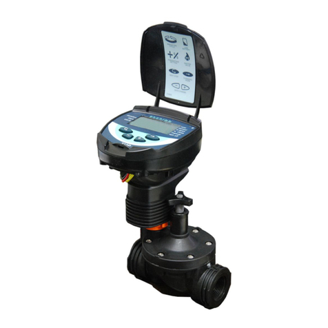
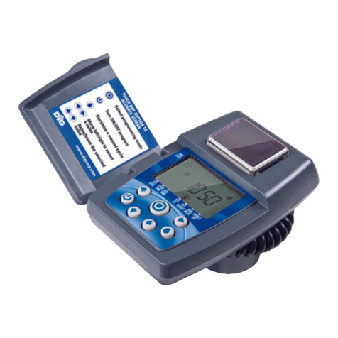
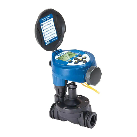
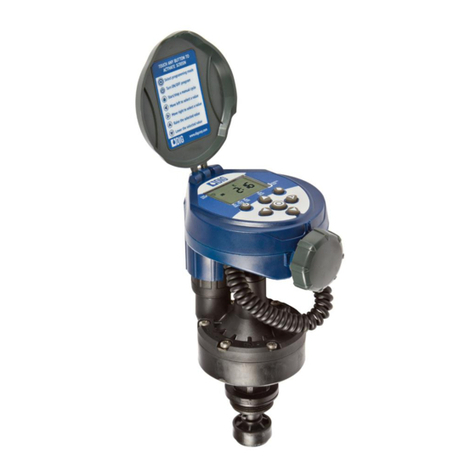
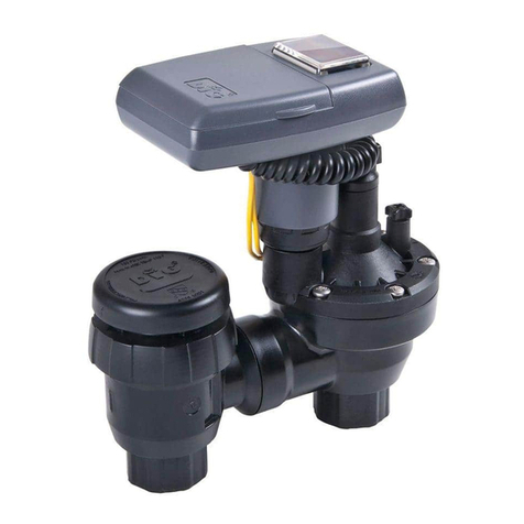
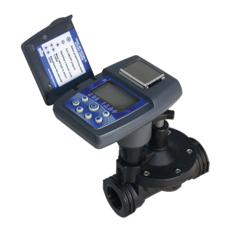
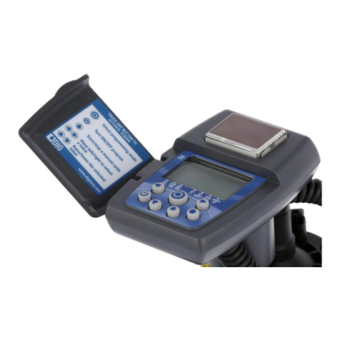
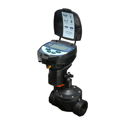
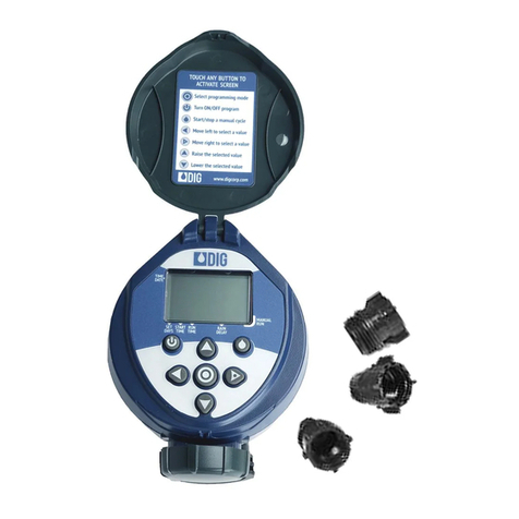
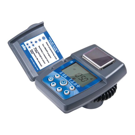
DIG 720A Series User manual

INSTRUCTION MANUAL
7X0A
Two, Four and Six Station Irrigation
Battery Operated Controller
720A-XXX | 740A-XXX | 760A-XXX

TABLE OF CONTENTS
INTRODUCTION.................................................................................................... 1
1. About the controller.................................................................................... 1
2. Component identification............................................................................ 2
3. Valve or wall mounting............................................................................... 2
4. Controller wire connection.......................................................................... 3
5. Battery installation ..................................................................................... 4
6. Installation recommendations .................................................................... 4
6.1 DC solenoid only installation................................................................ 4
6.2 In-line valve installation....................................................................... 6
6.3 Anti-siphon valve installation............................................................... 7
6.4 DC actuator installation ....................................................................... 8
7. LCD display icons & symbols identification................................................. 11
8. Controller buttons identifications ................................................................ 12
9. Programming ............................................................................................. 12
9.1 Setting time and date.......................................................................... 12
9.2 Selecting a program............................................................................ 14
9.3 Setting frequency ................................................................................ 15
9.4 Setting start times............................................................................... 16
9.5 Setting watering run times .................................................................. 18
9.6 Setting the SimpleSmart™option (set ET) ............................................ 20
9.7 Setting seasonal adjustment (monthly budget) .................................... 24
9.8 Rain delay mode ................................................................................. 25
9.9 Events off setting ................................................................................ 25
10. Manual watering....................................................................................... 27
11. Connecting a rain sensor .......................................................................... 28
12. Maintenance, troubleshooting and repairs................................................. 30
13. Technical assistance.....................................................................................32
14. Warranty................................................................................................... 33

INTRODUCTION
Thank you for purchasing one of DIG’s 7X0A Series, Two, Four or Six Stations Battery
Operated Controllers. This manual describes how to get the controller up and running
quickly. Please read this manual and become familiar with the basic functionality of
the controller, then save and use the manual as a reference for less common tasks
in the future.
1. ABOUT THE CONTROLLER
The 720A, 740A and 760A battery operated controllers employ the latest
irrigation programming features to allow for complete control of any irrigation
system. The controllers operate two, four or six stations and include a master
valve and rain sensor. The controllers are powered by two AA alkaline batteries
that can last up to one year using name brand alkaline batteries, depending
on the number of programs and valves in use. The 720A, 740A and the 760A
controllers are enclosed in a rugged, compact, waterproof housing (IP68) to
protect them from the elements and to ensure a long, trouble-free life.
Features:
• Operates up to six stations, master valve, and a sensor
• Four independent programs with five start times per each valve
• Watering frequencies including weekly, odd, even, and cyclical
• SimpleSmart™historical ET feature for spray heads and drip irrigation
automatically adjusts irrigation schedules monthly
• Can operate any number of valves at the same time
• Upon insertion of the batteries, the controller follows a start-up sequence to
test that each solenoid is closed
• Irrigation suspension (rain mode) with automatic restart of up to 99 days
• Monthly water budget up to 200% in 5% increments
• Daily and monthly programming restriction options to comply with city and
municipal watering restrictions
• After 15 minutes the controller screen turns off automatically to conserve energy
• Manual operation by valve or by program
• Program On/Off button allows the user to turn off the controller and reactivate
it as desired
• Utilizes RoHS compliant components
1

2. COMPONENT IDENTIFICATION
1. Controller cover (lid)
2. Quick programming reference label
3. LCD display with icon-based navigation
4. 5 button programming keypad
5. Battery compartment cap for two AA
alkaline batteries (
AA batteries not included
)
6. Yellow wire connection for rain sensor
7. Two, four or six 18” red solenoid wires,
two 18” white common wires, and one
18” black master valve wire
8. Solenoid mounting sleeve
9. Wall/valve box
mounting plate
3. VALVE OR WALL MOUNTING
.
The controller can be mounted directly on top of any of the valves installed or mounted into
the valve box.
3.1 VALVE MOUNTING:
1. Slide the controller mounting boss q
into the solenoid sleeve w to secure
and set it in the desired position on top
of the solenoid (Figure A).
NOTE: After mounting the sleeve to the solenoid, turning the solenoid
sleeve counter clockwise will turn the valve on, and turning the
solenoid sleeve clockwise will turn it off.
3.2 WALL MOUNTING:
1. Place the mounting plate e on the wall and secure using 4
screws (not included).
2. Slide the controller mounting boss r into the mounting
plate to secure (Figure B).
io
PROGRAM VALVE#
2
r
r
y
t
q
q
u
e
e
w
w
Figure B
Figure A

4. CONTROLLER WIRE CONNECTION
The 720A, 740A and the 760A controllers have a set of red wires numbered for each valve
as well as one black wire for master valve, two white wires for common, and one looped
yellow wire “S” for a rain sensor connection.
4.1 CONNECTING THE WIRES:
1. Connect each numbered red wire to a corresponding red DC solenoid wire (DIG model
#S305DC DC latching solenoid recommended).
2. Connect each white solenoid wire to
one of the two common white wires
from the controller using waterproof
splice connectors (Figure C).
NOTE: If a master valve is installed and
set to active, it will operate and open
with the first valve and will close with
the last valve.
WARNING: Do not strip the master
valve or sensor wires unless using a
master valve or rain sensor.
3. After installation, test each valve via the
solenoid by turning the solenoid one or two turns counterclockwise to open and clockwise
to close. If a valve remains open via a manual operation, you may need to examine the
solenoid and the adapter used to see that they are installed correctly. Make sure the
adapter and the solenoid are firmly secured but not over tightened.
WARNING: If using valves with built-in internal manual bleed levers: make sure
the lever is in the auto (closed) position. Do not move the manual lever after
installing the adapter and solenoid.
3
WIRE DISTANCES
Wire gauge Maximum wire length
14 AWG 100 feet
Figure C

5. BATTERY INSTALLATION
1. Turn the battery compartment cap
counterclockwise to open.
2. Install two, fresh, brand name, AA alkaline
batteries (not included) and note the proper
positive and negative orientation on the
underside of the controller body
(Figure D)
.
3. Insert and screw the battery cap clockwise
to close. Make sure to secure the cap tightly
by hand only. The controller display will appear with day, PM, and the hour digit
flashing. The controller is now ready to be programmed.
NOTE: Upon insertion of the batteries, the 720A, 740A, and 760A controllers will
follow a start-up sequence in which they send an off pulse to each of the attached
solenoids to verify that each of them is closed. This is delineated by all of the
valves appearing on the display, flashing. As a pulse is sent, each valve will stop
flashing, and, if they are not programmed, disappear from the display. After the
start-up sequence has finished, the time will appear on the display and program-
ming can proceed.
6. INSTALLATION RECOMMENDATIONS
6.1 S305 DC SOLENOID ONLY INSTALLATION:
1. Shut off the main water supply.
2. Remove the existing AC solenoids from each valve (if applicable).
NOTE: If adapting to an IRRITROL valve, remove the AC solenoid but leave the
existing solenoid adapter installed.
3. Select the appropriate solenoid adapter associated with the valve used (Figure E).
Figure D
Figure E
4
E FDCBA G
30-920
BERMAD 200, HIT
500, DOROT 80,
GRISWOLD 2000,
DW and BUCKNER
VB valves
30-921
RAIN BIRD DV, DVF,
PGA, PEB (1” only),
GB, EFB-CP, BPE,
PESB (1” only) and
ASVF valves
30-922
HUNTER ASV, HPV,
ICV, PGV, SRV, IBV
and ASVF valves
30-923
WEATHERMATIC
12000, 21000,
8200CR valves
30-924
IRRITROL series
100, 200B, 205,
217B, 700, 2400,
2500, 2600 and
TORO series 220,
P220 valves
30-925
SUPERIOR series
950, HUNTER HBV
and TORO series
252 valves (1.5”
and larger)
30-926
RAIN BIRD series PEB
and PESB
(1.5” and 2” only)
valves

NOTE:DIG has seven adapters available that will fit most valves. The three most
widely used models are included with each controller.
4. Screw the selected adapter into the valve solenoid cavity
until hand tight. If necessary, tighten with pliers, but do
not over tighten.
5. Thread the S305DC solenoid into each valve adapter and
tighten by hand only (Figure F).
6. Open the main water supply valve and pressurize
the main line; the valve may discharge water
momentarily but should then close by itself.
7. Test each valve via the solenoid by turning the
solenoid counterclockwise one or two turns to open,
or until you hear or see water flowing through the
valve, and turn it back clockwise to close (Figure G).
8. Mount the controller using the solenoid mounting
and connect the wires: refer to section 4.1 on page
3 for wire connection steps.
9. Test each valve via the controller: refer to section
10.1 on page 27 for how to perform a manual run.
Figure F
Figure G
5
Additional system components
Additional system components
Additional system components
Additional system components
A B C
ONOFF

6.2 IN-LINE VALVE INSTALLATION:
Operating pressure when used with DIG in-line valves: 10-150 PSI
(.7 to 10.5 bar)
Recommended operating pressure: Up to 80 PSI (5.5 bar)
NOTE: Wrap all fittings with Teflon tape. Do not use pipe cement on the
valve as this will damage the valve and void the warranty. Make sure when
wrapping fittings with Teflon tape that no excess gets into the internal
assembly. Tighten the fittings with a wrench but do not over tighten.
1. Shut off main water supply.
2. Install a manual ball or gate valve onto the PVC pipe upstream of the valve
manifold. Use Teflon tape to wrap all male threads with 4-6 layers of
Teflon tape.
3. Turn water supply on to flush the line and then shut the water off using the
ball or gate valve. If PVC glue is used, make sure to allow for adequate curing
time before opening the water supply line.
4. Make a manifold and install up to six inline valves and mount the controller to
the valve box or the solenoid (Figure H and I).
5. Mount the controller using the solenoid mounting and connect the wires: refer
to section 4.1 on page 3 for wire connection steps.
6. Test each valve via the controller: refer to section 10.1 on page 27 for how to
perform a manual run.
6
BELOW GROUND INSTALLATION WALL MOUNTING
FIGURE H
BELOW GROUND INSTALLATION VALVE MOUNTING
FIGURE I

6.3 ANTI-SIPHON VALVE INSTALLATION:
Operating pressure when used with DIG anti-siphon valves: 20-120 PSI
(1.4 to 10.5 bar)
Recommended operating pressure: 20-80 PSI (1.4 to 5.5 bar)
The 720A, 740A and the 760A controllers can be installed on top of DIG’s 3/4”
and 1” anti-siphon valves with model S305 DC solenoids.
NOTE: Wrap all fittings with Teflon tape. Do not use pipe cement on the
valve as this will damage the valve and void the warranty. Make sure when
wrapping fittings with Teflon tape that no excess gets into the internal
assembly. Tighten the fittings with a wrench, but do not over tighten.
WARNING:Make sure the anti-siphon valves are installed at least 6
inches higher than the highest sprinkler head on the system or back-
drainage may occur.
1. Flush main line until water runs clear before installation.
2. Shut off main water supply.
3. Make a manifold and install up to six anti-siphon valves with an attached
7X0A series controller to the PVC pipe manifold using 3/4” PVC male
adapters (Figure J) or 3/4” schedule 80 nipple.
4. Mount the controller using the solenoid mounting and connect the wires:
refer to section 4.1 on page 3 for wire connection steps.
5. Test each valve via the controller: refer to section 10.1 on page 27 for how
to perform a manual run.
NOTE:The arrow on the
anti-siphon valve body
indicates the direction
of water flow.
7
FIGURE J

6.4 DC ACTUATOR INSTALLATION:
Operating pressure: 20-150 PSI (1.4 to 10.5 bar)
Recommended operating pressure: 20-80 PSI (1.4 to 5.5 bar)
The 720A, 740A and the 760A controllers can be installed on top of DIG’s 3/4”
actuator valve model 305DC-013.
NOTE: If using a 1”anti-siphon, follow the steps in section 6.4.1 on how to
change to a 1” adapter for the actuator.
1. Shut off main water supply.
2. Remove the manual stem from the existing valve and temporarily remove the
anti-siphon cap (Figure K).
3. Replace any existing worn washers with the new ones provided (Figure L).
4. Install the actuator into the manual anti-siphon valve body by turning the
actuator clockwise. Tighten firmly, but do not over tighten (Figure M).
5. Turn the actuator flow control knob clockwise until it stops (Figure N).
6. Turn the main water supply on and pressurize the valve.
7. Mount the controller using the solenoid mounting and connect the wires: refer
to section 4.1 on page 3 for wire connection steps.
8
8
Figure K Figure L Figure M
MANUAL STEM
ANTI-SIPHON
CAP
WASHERS VALVE BODY

8. Test each valve via the controller: Press once, then press or and
select the valve number. Press again to start a manual run. A click will
be heard, indicating that the valve is open (On the display, will appear
on the lower right, will appear on upper left, and the valve running will
appear with an underscore under the valve number blinking).
9. Turn the actuator flow control knob counter clockwise to allow flow and
check the system to make sure that it is working properly (Figure O).
10. Press the again to deactivate the solenoid through the controller’s manual
button. A faint click will be heard and the valve will close. (The and
will disappear and water flow will stop).
If flow continues, turn the flow knob clockwise, one full turn at a time until
flow is stopped, and the valve is shut off.
NOTE: Turn the flow control knob clockwise to decrease flow,
counterclockwise to increase flow. For low-flow drip systems below
60 gallons per hour, the flow control knob should be turned no more than
1 to 3 turns counter-clockwise from the fully closed position.
9
FLOW CONTROL KNOB FLOW CONTROL KNOB
Figure N Figure O

6.4.1 CHANGING TO A 1” ADAPTER:
The valve actuator is factory set to fit a 3/4” brass manual anti-siphon valve. To
install the controller on an actuator with a 1” manual anti-siphon valve, the 3/4”
seat washer and adapter must be removed and replaced with the 1” adapter and
seat washer, which are included with the actuator (Figures P1-P6).
1. Turn the actuator so that the seat washer and the 3/4” threaded adapter
face up.
2. Using pliers or a 5/16” wrench, remove the seat washer screw by turning it
counterclockwise and pull off the 3/4” seat washer assembly (Figure P1).
3. Press the 3/4” threaded adapter down towards the actuator to ease the
tension on the retainer clip (Figure P2).
4. Next, place your thumb on one side of the retainer clip, and with a pair of
pliers, grip the other side of the retainer clip. Pull away and upwards from your
thumb, removing the clip from the base of the 3/4” threaded adapter. Then,
remove the adapter (Figure P3).
5. Install the 1” threaded adapter by pushing it onto the actuator stem and
making sure the notch on the adapter lines up with the notch on the stem of
the actuator (Figure P4).
6. Spread the retainer clip with your thumbs and push the retainer into the
adapter until it clicks (Figure P5).
7. Install the 1” seat washer assembly as shown. Insert the seat washer screw
into the bottom of the actuator stem and tighten by turning clockwise
(Figure P6). Do not overtighten.
Figure P2Figure P1
Figure P3 Figure P4
10

7. LCD DISPLAY ICONS & SYMBOLS IDENTIFICATION
1. Time and Date – Indicates current time and day
2. Program with underscore – Indicates which programs are selected and active
3. Set Watering Days – Indicates the scheduling setting
4. Start Time – Indicates the start time setting
5. Run Time – Indicates the run time setting
6. Smart Program – Indicates the SimpleSmart™programming setting or that a
SimpleSmart™program is active
7. Monthly Budget – Indicates the monthly budget setting or that monthly
budgeting is active
8. Rain Delay – Indicates the rain delay setting or that a rain delay is active
9. Events Off – Indicates the Events Off setting or that Events Off is active.
10. Manual Run – Indicates the manual run screen or that a valve or program is
being run manually
11. Master Valve – Indicates that the Master Valve is active
12. Valves with underscore – Indicates which valves are active
13. Battery Indicator – Flashes when batteries need to be replaced
14. Sensor – Indicates that a rain sensor is connected and active
15. Watering – Indicates that a valve is open and running
Figure P5 Figure P6
PROGRAM VALVE #
11
q
w
ea
1!
1#
1$1%
1@
rt y u i o

8. CONTROL BUTTONS IDENTIFICATION
TOUCH ANY BUTTON TO ACTIVATE SCREEN
Modify/Save a setting
Scroll Left/Right to select a setting or
Raise/Lower the selected value or
Turn On/Off program
Start/Stop a manual cycle
NOTE: The button will stop and prevent all watering until the system is
turned back on by pressing the button again. If the button is pressed
while modifying a specific program, only that program will be turned off
until it is turned back on.
9. PROGRAMMING
The following sections explain the programming features and the steps
necessary to assign irrigation schedules. To program the controller, use the
or buttons to select the desired setting, press to make the entry flash
(editable) and or to change the value. Only a flashing value can be
changed. Press again to finish changing a value and stop the entry
from flashing.
ENTER/EXIT
ADJUSTMENT MODE
TURN ON/OFF PROGRAM
START/STOP A MANUAL CYCLE
SCROLL TO SELECT PROGRAM
RAISE/LOWER THE
SELECTED VALUE
TOUCH ANY BUTTON TO
ACTIVATE SCREEN
12

9.1 SETTING TIME AND DATE:
9.1.1 SETTING THE CURRENT TIME AND DATE
NOTE: For the controller to operate properly, the current time and date must
be set.
1. Press to allow the time to be changed (the hours digits will flash).
2. Use or to change the hour (AM/PM
can be changed by increasing or decreasing
the hour).
3. Press to allow the minutes to be changed
and change the minutes using or .
4. Continue pressing and using or to
set the current month, the day, and the year.
5. Press to confirm your changes.
9.1.2 TO CHANGE THE TIME FORMAT
NOTE: The controller can display the time in either a 12 or 24 hour format.
1. On the main screen (the screen with the
current time on it), press and hold the
button for three seconds until the display
switches formats (AM/PM will either appear or
disappear depending on which format was set
previously).
13

Master valve
The master valve can also be turned on and off from this screen. If the master
valve is enabled, it will automatically open immediately with the first valve and
close immediately with the last valve during all operations.
9.1.3 TO TURN THE MASTER VALVE ON OR OFF:
1. On the main screen, press and hold
the button for three seconds until
appears (or disappears) below the hour
digits of the time.
Press to continue to the next step and choose a program.
9.2 SELECTING A PROGRAM:
The 720A, 740A and the 760A controllers have 4 different programs available for
programming (A to D). Each program has its own individual schedule, start times,
and durations. This setting will determine which program will get modified in
sections 9.3, 9.4, and 9.5.
9.2.1 CHANGING WHICH PROGRAM WILL BE MODIFIED:
1. Press to allow the program letter to be changed (A to D). The program letter
will begin to flash.
2. Press or to select which program to
modify.
3. Press to confirm the changes.
NOTE: As a shortcut, it is not necessary to use
the button to make changes on this screen;
simply press or to select a program.
NOTE: If you press while on this screen or the screens featured in section
9.3, 9 .4, and 9.5, it will turn only the selected program off and not prevent the
whole controller from watering like when pressed in any of the other screens.
14

Press to continue to set the watering frequency for the chosen program.
9.3 SETTING A FREQUENCY:
This setting determines which days the 720A, 740A or 760A controller will
operate. The controller has the ability to water on specific days of the week, even
or odd days of the month, or cyclical daily (from 1 to 30 days). Each program has
its own schedule. The controller’s default setting is to water on all specific days of
the week.
9.3.1 OPTION 1 – WATERING ON SPECIFIC DAYS OF THE WEEK:
1. Press or until you see in the bottom left corner of the display. By
default, all days are set to water on program A, and programs B through D are
set to OFF.
NOTE: Immediately above will be the icon which will let you know which
program you are programming.
2. Press and M(Monday) will begin to flash.
3. Press to turn watering off for that day and to turn it on for that day.
NOTE: An underline is shown under days that
are scheduled to water.
4. Advance through the days of the week using
or and repeat step 3 for each day.
5. Press to confirm your settings.
9.3.2 OPTION 2 – WATERING ON EVEN OR ODD DAYS:
1. Press or until you see in the bottom left corner of the display.
2. Press to modify this setting.
3. Press or until EVEnappears flashing on
the display. Press or to select Odd.
4. Press to confirm your settings.
15

9.3.3 OPTION 3 – WATERING ONCE EVERY X DAYS (CYCLICAL WATERING):
1. Press or until you see in the bottom left corner of the display.
2. Press to modify this setting.
3. Press or until 1 DAY appears flashing
on the display.
4. Press or to set the frequency (from
1 to 30 days).
5. Press to confirm your settings.
NOTE: To get from one option to any of the other options, press to
modify and then simply press or until the option desired appears
on the display, then follow the above steps for whichever option you would
like to set.
Press to continue on to setting start times for the chosen program.
9.4 SETTING START TIMES:
The 720A, 740A and 760A controllers can have up to five separate irrigation start
times per day per program.
9.4.1 TO SET A START TIME:
1. Press or until you see in the bottom left corner of the display.
2. Press to modify this setting.
NOTE: By default, start time 1 on program A is set to 6:00 AM and programs B
through D are set to OFF.
3. Press or to modify the hour.
4. Press and then or to modify the
minutes.
5. Press to confirm your changes.
16

9.4.2 TO SET ADDITIONAL START TIMES:
9.4.2.1 OPTION 1 – SCROLLING THROUGH EACH VALVE:
1. Press to modify this setting.
2. Press or consecutively until the number next to START changes (this is the
number of the start time).
3. Press or to change the time.
4. Repeat steps 2 and 3 until finished setting all desired start times.
5. Press to confirm your settings.
9.4.2.2 OPTION 2 – SETTING EACH VALVE INDIVIDUALLY:
1. As a shortcut, before pressing to modify this setting, press or to
change the number next to START. This can also be used to view all start times
that have been set.
2. Press when the desired start time appears.
3. Modify the start time, then press to confirm your settings.
9.4.2.3 TO DELETE A START TIME:
1. Navigate to the start time that will be deleted using Option 1 or Option 2 above.
2. Press to modify this setting.
3. Press or on the hour digit until the
display shows OFF (OFF appears between
11:00 PM and 12:00 AM).
4. Press to confirm your settings.
Press to continue on to setting run times.
17

9.5 SETTING WATERING RUN TIMES:
This setting determines the length of time each valve on the 720A, 740A and 760A
controllers will remain open to allow watering during operation.
For example, setting a run time of 10 minutes on valve 1 will allow the controller
to run valve 1 for 10 minutes on each start time during each day the program is
active. Depending on which model obtained, up to 2, 4, or 6 valves will be available
to set for each program.
9.5.1 TO SET WATERING RUN TIMES:
1. Press or until you see shown on the bottom of the display.
2. Press to modify this setting.
NOTE: By default, the run time of valve 1 on program A is set to 5 minutes
(0:05) and programs B through D are set to OFF. The valve currently being
looked at viewed is underlined on the display near the icon centered
below the run time.
3. Press or to set the hours.
4. Press and then or to set the minutes.
5. Press to confirm your settings.
9.5.2 TO SET RUN TIMES FOR THE REST OF THE VALVES:
9.5.2.1 OPTION 1 – SCROLLING THROUGH EACH VALVE:
1. Press to modify this setting.
2. Press or consecutively until the number
of the valve to be changed
is underlined.
3. Use or to set the hours and minutes.
18
This manual suits for next models
2
Table of contents
Other DIG Controllers manuals
Popular Controllers manuals by other brands
RolloHomeControl
RolloHomeControl 35002319 Operating and assembly manual
Turbosmart
Turbosmart IWG75 Twin Port manual
Truma
Truma MonoControl CE-0085CT0438 operating instructions
WaterLine Controls
WaterLine Controls WLC-9000 installation instructions
Emerson
Emerson FISHER T205B instruction manual
rotork
rotork LP/S Series Installation, Comissioning and maintenance manual
