enphase IQ Battery-3T-1P-NA User manual
1
QUICK INSTALL GUIDE (Models IQ Battery-3T-1P-NA and IQ Battery-10T-1P-NA)
Install the Enphase IQ Battery System
To install the Enphase IQ Battery 3T system or IQ Battery 10T system and the Enphase wall-mount bracket, read and follow all warnings and instructions in
this guide. Safety warnings are listed at the end of this guide. These instructions are not meant to be a complete explanation of how to design and install an
energy storage system. All installations must comply with national and local electrical codes and standards. Only qualied electricians shall install, trouble-
shoot, or replace the IQ Battery 3T or IQBattery 10T.
The IQ Battery system includes the IQ Battery(ies) with integrated Enphase IQ Microinverters. The IQGateway measures PV production and home energy
consumption. The IQ Battery system senses when it is optimal to charge or discharge the battery so that energy is stored when it is abundant and used
when scarce. IQ Battery systems are capable of providing backup power when an IQ System Controller is installed at the site.
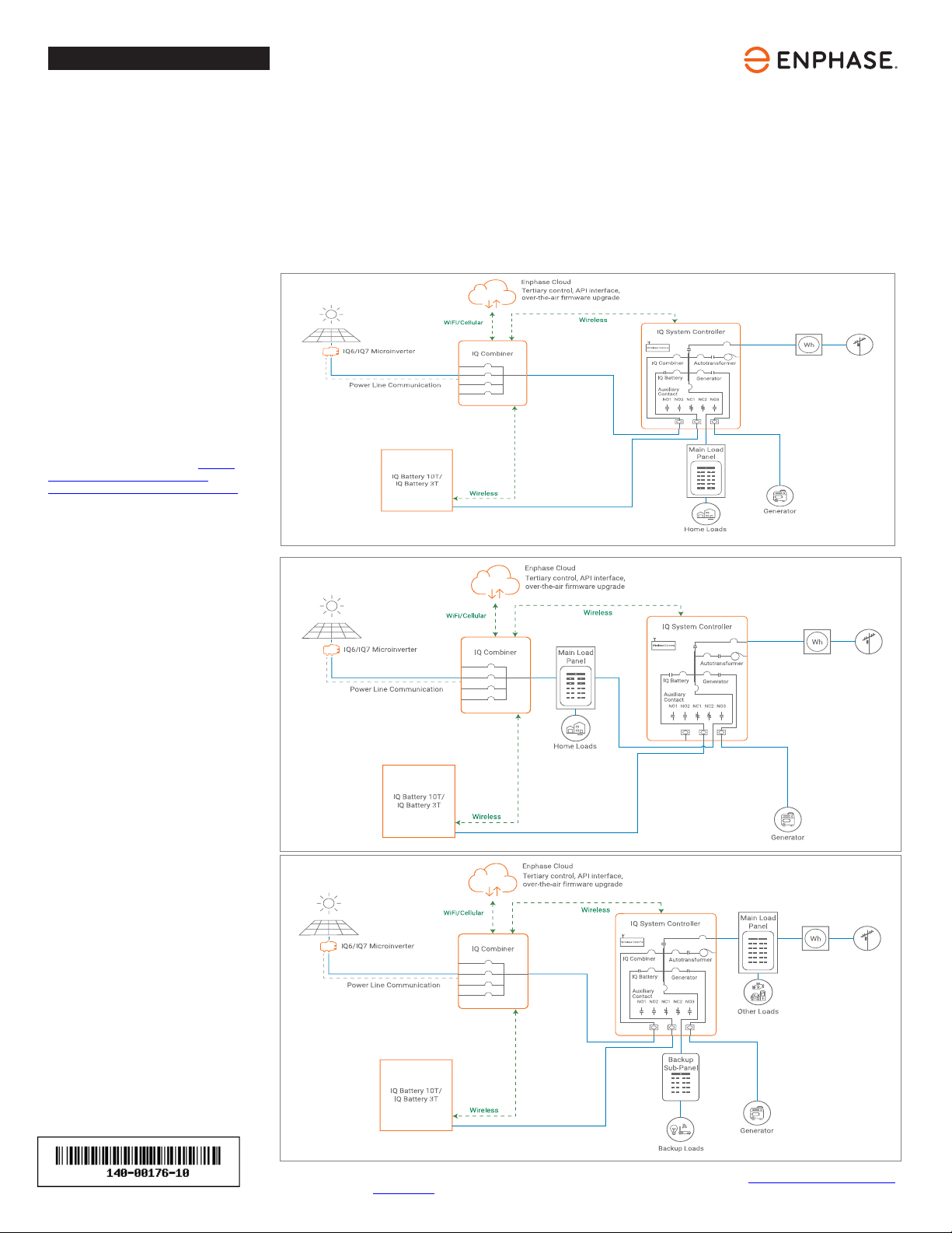
Five unique installation
scenarios are shown:
Whole home backup with IQ System
Controller as service entrance and
PV combiner connected to IQ System
Controller. This is the preferred
conguration for back up of the entire main
load panel. This conguration supports up
to an 80 A breaker for the PV circuit and an
80 A breaker for battery storage.
Whole home backup with IQ System
Controller as service entrance and PV
combiner connected to main load panel.
This is the preferred conguration when you
back up the entire main load panel, and the
size of the PV combiner circuit is more than
80 A. In this conguration, the PV combiner
circuit connection space in IQ System
Controller is left vacant. When existing PV
combiner circuits are connected to the main
load panel, and you want to add battery
storage to the system, you can keep the PV
combiner connected to the main load panel
and connect only the battery storage to IQ
System Controller.
Partial home backup with main load panel
as service entrance and PV combiner
connected to IQ System Controller. When
PV circuits breaker size is less than 80 A,
this is the preferred conguration for partial
home backup with subpanel.
© 2023 Enphase Energy. All rights reserved. Enphase, the e and CC logos, IQ, and certain other marks listed at https://enphase.com/trademark-us-
age-guidelines are trademarks of Enphase Energy, Inc. in the US and other countries. Data subject to change. Rev 10/2023-07-05
NOTE:
1. For M215/M250 connection to Enphase
Energy System, refer tech brief at https://
enphase.com/download/enphase-
energy-system-planning-guide-tech-brief.
2. M Series Microinverters require IQ Gateway.
(optional)
(optional)
(optional)
2
PREPARATION
A ) Inspect the packaging and the IQ Battery(ies) for damage, such as cracks,
dents, or leaking electrolyte. Do not install or use the IQ Battery(ies) if it
has been damaged in any way. If damaged, contact your distributor for
replacement.
B ) Ensure that your kit includes the following IQ Battery components:
• The IQ Battery 10T includes three batteries and two interconnect
cable assemblies, an IQ Battery 10T triple-width cover, top, middle, and
bottom mounting brackets.
• The IQ Battery 3T includes one battery, and single-width cover with a
single-width mounting bracket.
NOTE: Check the “Energize By” label on the shipping box to verify that
the IQ Battery(ies) will be installed by the date shown. If the date has
passed, contact your distributor for next steps.
* WARNING! Risk of injury. Take care when lifting. The IQ Battery unit
is heavy (40.5 kg/89.3 lbs) and requires two persons to lift.
C ) Ensure you have the following required Enphase items for backup systems:
• An IQ System Controller with microgrid interconnect device (MID)
functionality and an Enphase IQ Combiner.
• The IQ Battery system requires an Internet connection through the IQ
Gateway in the IQ Combiner. Failure to maintain an Internet-connec-
tion may have an impact on the warranty. See enphase.com/warranty
for full terms.
• Wireless communications kit (COMMS-KIT-01) is to be installed at
the IQ Gateway for communications with IQ Battery and IQ System
Controller. It includes USB cable for connection to IQ Gateway/IQ
Combiner and allows wireless communication with IQ Battery and IQ
System Controller.
D ) Make sure you also have the following required items:
• Mounting location that is structurally suited to bear the weight of
the IQ Battery(ies). Total weight for the IQ Battery 3T, including the IQ
Battery base unit, cover and wall mount bracket, is 48.8 kg (107.6 lbs).
Total weight for the IQ Battery 10T, including the three IQ Battery base
units, cover, and wall mount bracket, is 152.1 kg (335.3 lbs).The wall
must contain blocking studs that can bear the battery weight or can
be of masonry or other suitable structure.
• Tools: conduit (with ttings and tting tools), drill 5/32 inch pilot bit (or
metric equivalent), screwdriver, socket wrench, torque wrench, level,
wire stripper, and stud nder if installing on studs.
• Fasteners for wall mount bracket. Slots are 9.2 mm (0.36″). Check with
a structural engineer and local standards for requirements:
Single-width bracket for IQ Battery 3T: A minimum of three #20(5/16″)
lag bolts or screws, 7.6 cm (3 inches) long (depending on attachment
wall).
Triple-width bracket for IQ Battery 10T: A minimum of fteen #20
(5/16″) lag bolts or screws, 7.6 cm (3 inches) long (depending on
attachment wall).
• Washers for use between fastener heads and wall-mount bracket.
• Copper conductors: No. 14 - 8 AWG (11 mm/7/16 inch strip length)
copper conductors (rated at 75°C or 90°C) for terminals.
Conduit ttings: 1/2 inch or 3/4 inch (left side) hubs are required for
all installations, and NEMA Type 3R conduit ttings (hubs) are needed
when installing outdoors.
• Overcurrent protection: The overcurrent protection in IQ Battery is not branch
circuit overcurrent protection and cannot be relied upon for that purpose. The
branch circuit overcurrent protection is located in IQ System Controller or,
when combining , in a separate combiner. See the IQ System Controller Quick
Install Guide for more information.
• Personal protective equipment (PPE) for handling lithium batteries as
required by local safety standards.
• Protective gloves for protection against sharp edges.
E ) Verify that main service is 120/240 VAC, and not 208/120 VAC. IQ Batteries
cannot be installed where L1 to L2 measures 208 VAC.
F ) Note that the rated energy capacity of the battery is 3.36 kWh.
G ) Install the PV system and the IQ Combiner as directed by the Enphase
installation manuals.
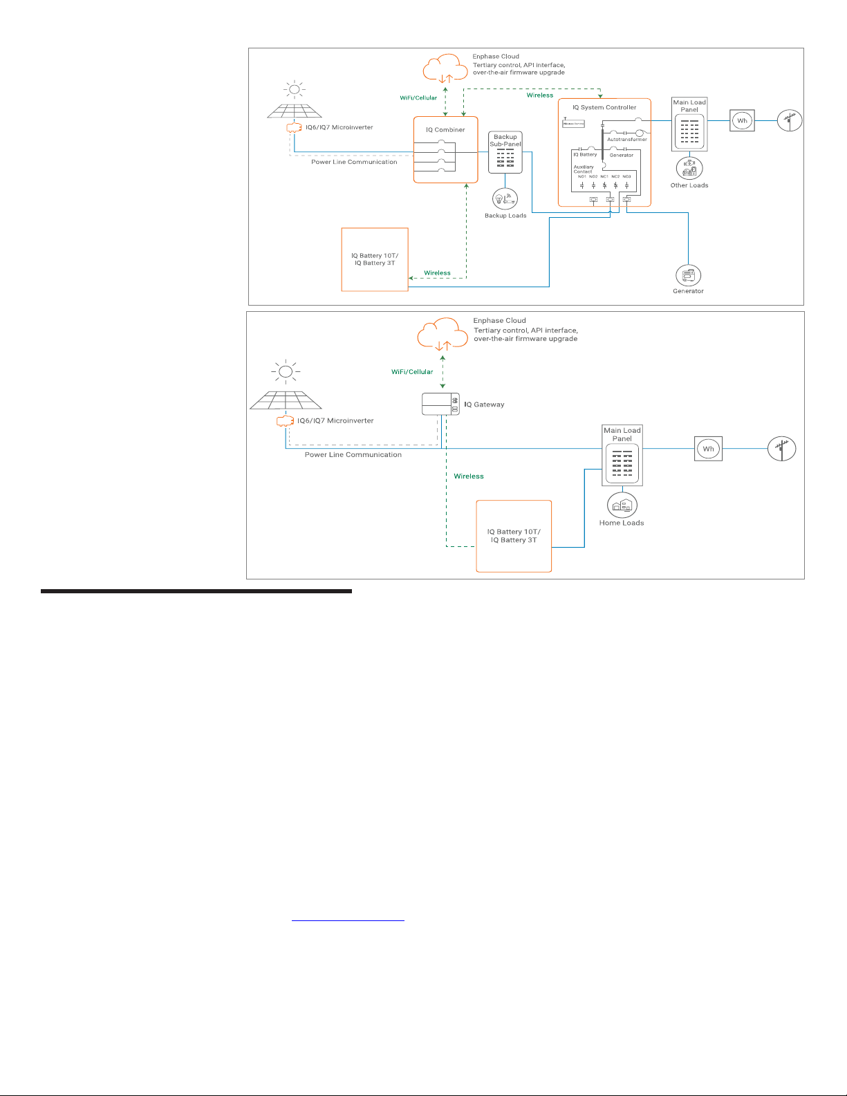
Self-consumption, no IQ System Controller.
The preferred conguration when adding
battery storage and PV for self-consumption
in a grid-tied application with no option for
backup during outages. PV and IQ Battery
will not operate when the grid is unavailable.
Partial home backup with main load panel
as service entrance and PV combiner
connected to subpanel. This is the
preferred connection conguration for
partial home backup using a subpanel
when the PV circuit breaker size is more
than 80 A. The space available in IQ System
Controller for combiner (solar) connection
is left vacant.
(optional)

3
INSTALLATION
Plan a location for the IQ Batteries
The IQ Battery housing is NEMA type 3R and can be installed indoors or out-
doors. The terminal blocks accepts copper conductors of No. 14 - 8 AWG.
A ) Following local standards, choose a well-ventilated location where
the ambient temperature and humidity are within -15°C to 55°C
(5°F to 131°F) and 5% to 100% RH, non-condensing, preferably out
of direct sunlight. The optimum ambient temperature range for
installation location is 0ºC to 30ºC (32ºF to 86ºF). Provide smoke
alarms in the residence in accordance with building, re and
installation codes.
*WARNING!IQ Batteries have been evaluated by UL Solutions to
UL9540A Standard for outdoor and non-habitable indoor residential
installations. Installations in nished, non-habitable indoor spaces
such as detached and attached garages, utility closets, basements
and storage or utility spaces shall be permitted.
B ) Ensure that the mounting location can sustain the total weight
of the IQ Batteries and mounting bracket. Total weight for the IQ
Battery 3T, including the IQ Battery base unit, cover and wall mount
bracket, is 48.8 kg (107.6 lbs). Total weight for the IQ Battery 10T,
including the three IQ Battery base units, cover, and wall mount
bracket, is 152.1 kg (335.3 lbs).
*WARNING! The installer should install blocking between studs
to ensure that no single stud carries the entire weight load of the
IQ Batteries.
C ) Plan the mounting location to be at least 15 cm (six inches) off the
ground and 15 cm (six inches) from the ceiling for IQ Battery 3T and
IQ Battery 10T.
NOTE: Wherever local codes allow a smaller separation distance
for Energy Storage installations, the minimum spacing around IQ
Battery 10T must be at least six inches from the top, bottom, left,
and right side of the product.
Keep the IQ Battery away from falling or moving objects, including
motor vehicles.
*WARNING!If mounted in the path of a motor vehicle, we
recommend a mounting height that is 91 cm (thirty-six inches)
minimum above the oor.
D ) Ensure that there are no pipes or electrical wires where you plan to drill.
E ) Plan to maintain at least 91 cm (thirty-six inches) of clearance in
front of each IQ Battery.
F ) Consider the dimensions of the IQ Batteries, easy access, height,
and length of cable when selecting the location.
G ) Select a location where you can interconnect to the IQ System
Controller.
H ) Follow all local standards and restrictions set forth by authority
having jurisdiction (AHJ).
I ) For installations with more than one IQ Battery 10T units, there
must be a separate load center, subpanel, or circuit combiner
with over current protection to combine the circuits, and you must
run only one circuit for all the IQ Battery units to the IQ System Con-
troller (or to IQ Combiner for grid-tied-only installations). You must
select proper conductors and circuit breakers for these circuits
according to local codes, standards, and other applicable require-
ments. The circuit breakers used would have to be suitable for
back-feeding, per NEC 408.36(D). IQ System Controller supports up
to a maximum of 80 A breaker for IQ Battery connection circuit.
Up to four IQ Battery 10Ts or twelve IQ Battery 3Ts can be safely
connected to 80 A load center.
To do this, you can install as per the options presented in the image
shown in next column.
J ) The maximum conductor size for IQ Battery 3T and IQ Battery 10T is
8 AWG and the maximum breaker rating with this conductor size is
40 A.
1
Install the AC disconnect
Following all local codes and standards:
A ) Install an AC disconnect that can break the maximum rated current
of the branch circuit under load. The AC disconnect must be readily
accessible and located within line-of-sight of IQ Battery, per NEC
2017 706.7 (A).
B ) Each IQ Battery unit is suitable for use with up to No. 8 AWG wires
on a maximum 40 A branch circuit. If more than 32 A of IQ Batteries
(corresponding to a 40 A branch circuit) are installed, a separate
subpanel must be installed between the IQ Battery units and IQ
System Controller to combine the IQ Battery circuits together. All
circuit breakers in the subpanel must be suitable for back-feeding, per
NEC 408.36 (D).
C ) Verify that AC voltage at the site is within range: single-phase L1 to
L2 voltage must measure between 211 VAC and 264 VAC, while L-N
should measure between 106 VAC and 132 VAC.
2
Prepare to install the wall-mount bracket
A ) Make sure that the planned position for the wall-mount bracket
meets clearance requirements as shown. The image depicts a
single-width bracket for the IQ Battery 3T, but clearances and
requirements are the same when installing a triple-width bracket for
the IQ Battery 10T.
B ) Ensure that the mounting location can sustain the weight of the IQ
Batteries and mounting bracket. Total weight for the IQ Battery 3T
including the mounting brackets and cover is 48.8 kg (107.6 lbs),
while the total weight for IQ Battery 10T including the mounting
bracket and cover add up to 152.1 kg (335.3 lbs).
C ) Starting at installation position closest to the power source, mark a
level line on the wall as a guide.
* WARNING! Multiple risks. Make sure not to drill or attach into
electric wiring or pipes that are in the wall!
3
Mounting on vertical stud
IQ Battery 3T
NOTE: The above shown image is just for reference. Use other slots
on the wall mount if additional xing is required for stability (to be
assessed by the installer).
40 A40 A
Storage input
10T
2
10T
2
10T
2
10T
2
10T
2
10T
2
1) 2)
IQ SC
1
Storage input
IQ SC
1
20 A 20 A20 A 20 A
10T
2
10T
2
10T
2
10T
2
3)
Storage input
IQ SC
1
Wood stud
*WARNING!Parallel power production sources only. Do not connect
load circuits.
1. IQ System Controller
2. IQ Battery 10T

4
Vertical +5° inclination -5° inclination
430 mm
775 mm
188mm
IQ Battery 3T — single-width bracket
A ) Place the wall-mount bracket on the wall so that the mounting holes of the
bracket align with the center of the stud.
* WARNING! Risk of injury and equipment damage. Use the unit mounting
holes only to mount the base unit of IQ Battery to the wall mount. Do not
use the unit mounting holes to secure the bracket to the wall.
B ) Use a level to keep the wall-mount bracket leveled.
C ) Use #20 (5/16″) screws (or masonry attachments for masonry) to attach
the bracket using one screw and washer for each slot (9.2 mm/0.36″). Use
minimum of three screws in each mounting bracket. Tighten all screws to
manufacturer specied torque values.
D ) Verify that the wall-mount bracket is solidly attached to the wall.
* WARNING! Risk of injury and equipment damage. Do not mount an IQ
Battery 3T on a bracket that is not properly mounted.
E ) If installing additional batteries, install adjacent wall-mount brackets, as
needed. Be sure to align the mounting holes in the wall-mount bracket to
the center of the wall stud. You may install another row of brackets above
the one already installed. Maintain at least 15 cm (six inches) vertical
clearance between rows and and 2.54 cm (1 inch) horizontal clearance
between units of IQ Battery 3T installations, and ensure that the wall can
support the structural load (weight) of the installation.
* WARNING! Risk of injury and equipment damage. Do not install more than
three IQ Battery 3T units per 20 A branch circuit.
4
D ) The screws on the area below the red dotted rectangle would be
utilized in the next steps.
E ) Verify that the wall-mount bracket is solidly attached to the wall.
F ) Place the bottom wall-mount bracket below the middle bracket
aligning the holes and edges as shown in the image below:
G ) Use three number of #20 (5/16″) screws and utilize three wall mount
slots that are common between middle and bottom wall-mount
brackets to attach bottom wall mount bracket on wall.
H ) Place the top wall-mount bracket sitting on top of middle wall-mount
bracket as shown in the image below:
I ) Use six number of #20 (5/16″) screws and utilize six wall mount slots
to attach top wall mount bracket on the wall.
* WARNING! Risk of injury and equipment damage. Do not mount IQ
Battery 10T batteries on a bracket that is not properly mounted.
J ) If installing additional batteries, install adjacent wall-mount brackets,
as needed. Be sure to align the mounting holes in the wall-mount
bracket to the center of the wall stud. You may install another row of
brackets above the one already installed.
Maintain at least 15 cm (six inches) vertical clearance between rows
and and 15 cm (six inches) horizontal clearance between units of IQ
Battery 10T installations, and ensure that the wall can support the
structural load (weight) of the installation.
* WARNING! Risk of injury and equipment damage. Do not install more
than one IQ Battery 10T unit per 20 A branch circuit.
Allowable tilt from vertical for IQ Battery installation:
Single-width mounting bracket
Front view Angle view
Wall mount
slots
Unit
mount
key
holes
478 mm
43 mm
418 mm
9.2 mm
* If the difference in atness is more than 2 mm, recommend installing
a substructure like unistrut for better alignment of the units.
IQ Battery 10T
MOUNTING SURFACE
IQ Battery 3T
MOUNTING SURFACE
Mounting Surface Flatness (across
the installation width and height)
recommended to be within 2 mm*
Install the IQ Battery 3T (single-width) or IQ Battery 10T
(triple-width) wall mount bracket
Follow the instructions below for installing the bracket.
* WARNING! Risk of injury and equipment damage. Attach the wall mount to
the wall so that it is no more than ve percent tilted from vertical. See the follow-
ing image for reference:
IQ Battery 10T — triple-width bracket
A ) Place the middle wall-mount bracket on the wall so that the mounting
holes of the bracket align with the center of the stud, and the mounting
holes on the left and right align with the adjacent studs.
* WARNING! Risk of injury and equipment damage. Use the unit mounting
holes only to mount the base unit of IQ Battery to the wall mount. Do not
use the unit mounting holes to secure the bracket to the wall.
B ) Use a level to keep the wall-mount bracket leveled.
C ) Use #20 (5/16″) screws (or masonry attachments for masonry) to attach
the bracket using one screw and washer for each slot (9.2 mm/0.36″). Use
a minimum of six screws in each middle mounting bracket (within the red
dotted rectangle) to support three IQ Battery units. There is an array of
slots so that you can choose those that allow you to mount the bracket on
studs. Tighten all screws to manufacturer specied torque values.
1270 mm
417 mm
417 mm
417 mm
61 mm
61 mm 284.5 mm
Triple-width mounting bracket Wall mount
slots
Unit mount
key holes
5
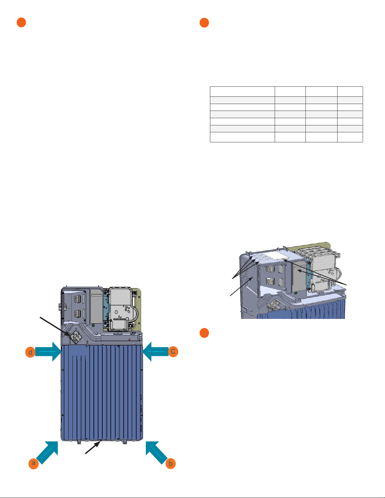
Mount the IQ Battery(ies) on the wall
* WARNING!Risk of injury. Take care when lifting. Each IQ Battery
base unit is heavy (40.5 kg/89.3 lbs) and requires two persons to lift.
* WARNING! Risk of injury and equipment damage. Avoid dropping
the IQ Battery(ies). Doing so may create a hazard, cause serious injury,
and/or damage the equipment.
* WARNING! Risk of injury and equipment damage. Protect the IQ
Battery(ies) from impact damage and improper use.
* WARNING! Risk of injury and equipment damage. Do not hold the
microinverters to lift the unit during installation.
A ) Two person together must lift a single IQ Battery base unit from the
packaging and place it in upright position (as shown in image) on a
at surface.
B ) Locate the IQ Battery lifting points:
C ) The rst person lifting must use points aand d(as shown) to lift the
battery.
D ) The second person lifting must use points band c(as shown) to lift
the battery.
E ) Together, lift the IQ Battery and bring it to the already mounted
bracket.
F ) Hold the IQ Battery straight so that the four bolts on the back of the
IQ Battery pass through the four key hole slots on the corner of the
mounting bracket.
* WARNING! Risk of injury and equipment damage. Do not release
the IQ Battery unit until you ensure that the IQ Battery unit is fully
seated in the wall-mount bracket shelf.
G ) Once all four battery bolts fully pass through the mounting bracket
key hole slots, lower the battery down until fully seated within the
wall-mount bracket and set into the bottom of the key holes.
H ) Attach the battery to the mounting bracket aligning the screw hole
at the bottom of the battery with the screw hole at the bottom of the
bracket. Tighten the bottom screw to 8 N m (70.8 lb-in).
I ) To record the installation of each IQ Battery base unit, scan the serial
number label using Enphase Installer App and your mobile device.
5
C
b
a
d
Prepare for eld wiring
+ DANGER! Risk of electric shock. The DC switch must be in the
locked position before performing this step.
A ) Drill the left wall of eld wiring comparent to accommodate the conduit.
B ) Connect eld wiring to the top three terminal blocks.
C ) Size the conductors (Lines and Ground) to account for voltage rise and
to conform to the tables below. Design for a voltage rise of less than
2%. IQ Battery can use any circuit breaker size between 10 A and 40 A.
Breaker rating and wire size are installation dependent.
Number of
IQ3T/IQ10T units
Current (A) Minimum wire
size (AWG) Breaker
rating (A)
1*IQ3T 5.3 14 10
2*IQ3T 10.7 14 15
3*IQ3T or 1*IQ10T 16.0 12 20
4*IQ3T or (1*IQ10T + 1*IQ3T) 21.3 10 30
5*IQ3T or (1*IQ10T + 2*IQ3T) 27.7 8 35
6*IQ3T or 2*IQ10T or
(1*IQ10T + 3*IQ3T) 32.0 8 40
*IQ3T refers to IQ Battery 3T
*IQ10T refers to IQ Battery 10T
In all cases in the table, it is possible to always use larger conductors
and a breaker sized for that conductor or smaller. For Example in row 3,
with 3 × IQ3T or 1 × IQ10T, it is possible to use:
a) 12 AWG wire with 20 A breaker, or
b) 10 AWG wire with 20 A or 30 A breaker, or
c) 8 AWG wire with 30, 35, or 40 A breaker
+ DANGER! Risk of electric shock. Check that the dedicated circuit
breaker protecting the branch where the IQ Battery(ies) will be
connected is turned off before wiring.
* WARNING! Risk of equipment damage. The DC switch must be
OFF before installing, otherwise IQ Battery will try to form a grid.
6
Location for
conduit cut out
Finished
goods seri-
al numbers
labels
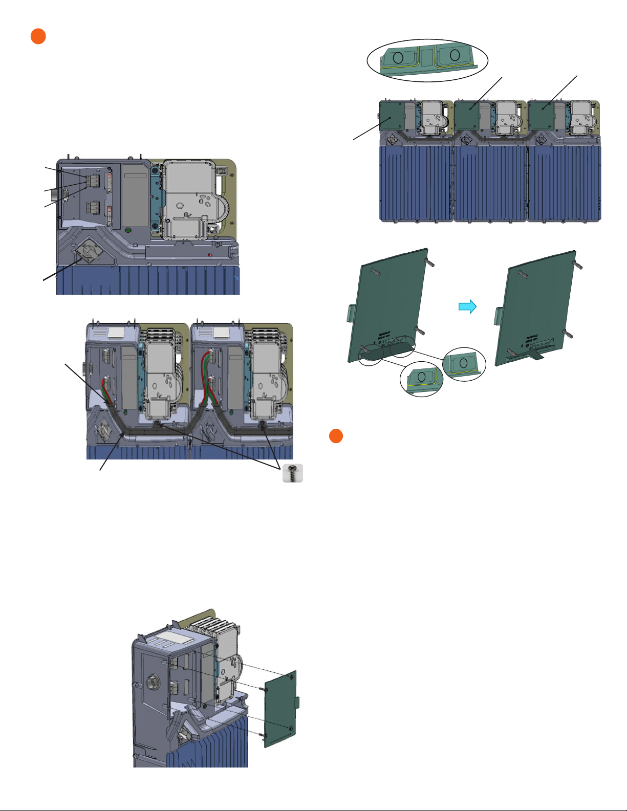
Install conduit and eld wiring
+ DANGER! Risk of electric shock. The DC switch must be in the
locked position before performing this step.
A ) If installing an IQ Battery 10T, install the interconnect cable assembly.
• Face the front of the batteries, and insert the interconnect cable
assembly through the front cable slot from within the eld wiring
comparent, with the arm of the interconnect cable pointing up, making
a “U” shape.
B ) Using the conductors and suitable conduits, connect the AC disconnect
and the rst adjacent IQ Battery. Use the conduit openings provided
to connect the conduit and pass the wires through them. Note that if
an IQ System Controller is in line-of-sight, the breaker can service as a
disconnect.
* WARNING! Risk of equipment damage. Do not modify or rewire the
pre-installed wiring or bonding connections in the eld wiring comparent.
* WARNING! Risk of equipment damage. Always connect to two Lines
(active) and one ground.
(CONTINUED ON NEXT PAGE)
7
PCBA Serial
Numbers
Bottom screw hole
DC Switch
6
Install conduit and eld wiring (continued)
C ) Connect each wire in the eld wiring comparent to its corresponding
terminal (Lines and Ground). Each terminal accepts two 14-8 AWG
conductors (11 mm/7/16 inch strip length). Tighten to 1.6 N m (14
lb-in).
D ) If installing an IQ Battery 10T, secure the inter-connection cable assem-
bly between the IQ Battery units. You must connect the interconnect
cable to the bottom three terminal blocks for the left unit and top three
terminal blocks for the right unit.
7
+ DANGER! Risk
of electric shock. The
system is not ready
to be energized! Do
not close the circuit
breaker or turn ON the
DC switch.
1
2
2
3
1
4
1. Terminal for L1 in
from conduit
opening
2. Terminal for L2
in from conduit
opening
3. Terminal for
ground in from
conduit opening
4. DC Switch
Interconnect cable
Ensure that the
interconnect
cable is properly
seated in the
slot.
Assemble using two
M4 screws from the
c o v e r a c c e s s o r i e s k i t :
Tighten to 1.9 N m/16.8 lb-in.
E ) After all wires in the eld wiring comparent are connected and secured,
check that there are no exposed conductors.
F ) If connecting additional IQ Batteries, use another conduit and another
set of wires to connect between eld wiring comparents.
G ) Gently arrange all the wires and connectors inside the eld wiring
comparent.
H ) Secure the eld wiring comparent cover. Use a cross-head screw driver
to tighten the cover screws to 2.3 N m (20.3 Ib-in).
I ) Break tab 1, tab 2,
or both tabs on the
eld wiring door
along the yellow
lines indicated for
interconnect cable
entry as shown.
J ) Do not break tabs
when installing the
IQ Battery 3T.
Cover and energize the system
*WARNING: Before energizing, make sure that ALL IQ Batteries in
the system are properly installed and conductors terminated.
* WARNING! Risk of equipment damage. Ensure that no wires are
pinched before replacing the cover.
NOTE: Check the box for updates on cover installation instructions.
IMPORTANT: The section 8 and 9 will depict instructions for assemby
and disassembly of IQ Battery 3T cover, simillar instructions are appli-
cable for IQ Battery 10T cover.
A ) Check that the eld wiring comparent cover(s) for all IQ Batteries in the
system are closed and secured.
*WARNING: Complete the IQ System Controller and IQ Combiner
installations before turning the DC switch(es) ON.
+DANGER: Risk of electric shock. Before continuing, check that
IQ Battery units are properly wired, and ground connection does not
have a L1 or L2 connection, as this introduces a safety hazard.
• Apply AC power to the IQ Battery circuits. Do NOT turn ON the IQ
Battery DC switch(es).
• Use a Voltmeter to measure the IQ Battery chassis metal to ground
(e.g., grounded conduit) voltage and ensure there is no AC voltage
source present. If wiring is incorrect, a ground fault may exist, and the
AC voltage may read ~120 VAC. If voltage is present, DO NOT touch the
chassis, and immediately remove AC power from the IQ Battery circuits
and correct the wiring.
+DANGER: Risk of electric shock. AC voltage might be present at
the output, when the DC switch is ON.
*WARNING: Branch Circuit protection for IQ Battery MUST be ON
(with AC voltage present) before turning DC switch ON. Wait for 15
seconds after turning branch circuit protection ON and check that
LED on IQ Battery is ON (Any color LED is ON) before turning DC
switch ON.
8
12
Tab 1 and 2 to
be broken Tab 2 to be
broken
Tab 1 to be
broken
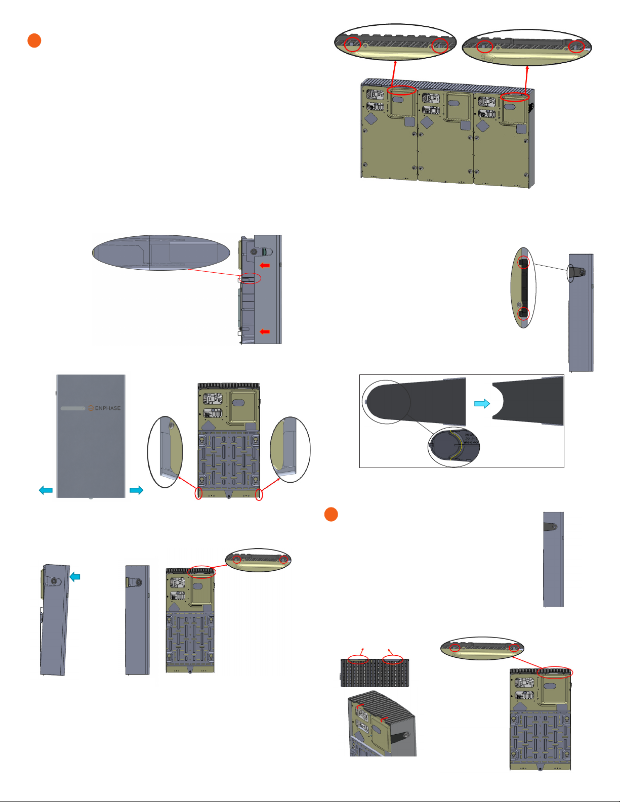
7
C ) Slide the IQ Battery cover in the indicated direction so that the hook of
the cover in the highlighted region goes into the slot provided for it in the
main unit (both sides of the main unit).
D ) Pull out the lower edges while sliding in the
cover and ensure that the tabs are locked to the back
plate as shown below before releasing.
E ) Once the cover reaches the position as shown in the side view image.
push the top portion of the cover and make sure that the cover is
locked in place, in the indicated regions.
8
Before pushing
into place: Locked into
place:
F ) After assembling the IQ Battery cover, remove the break-out tab from
the conduit cover and assemble with the ribs
snapping in as shown:
G ) Break the conduit cover tab along the yellow
line as indicated before assembling to the main
unit:
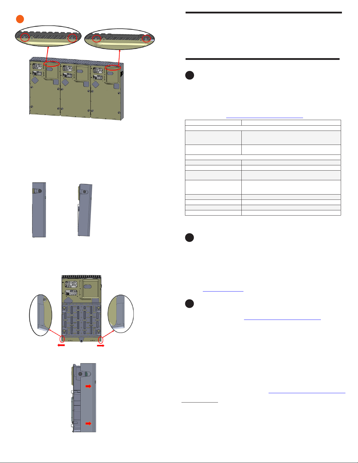
9
Disassembly of the IQ Battery cover
A ) Remove the conduit cover from the IQ Battery cover.
B ) Using the hand access slots pull the top plastic grill slightly in the
direction shown below (in order to unlock the top plastic cover from the
ribs highlighted in red):
IQ Battery 10T cover
IQ Battery 3T cover
IQ Battery 3T cover
Hand access slots
NOTE: Only for reference purpose, the IQ Battery 10T cover image is
shown above for locking.
Cover and energize the system (continued)
B ) Turn ON the AC power rst (branch circuit protection) and then turn
ON the DC switches of the IQ Batteries.
NOTE: Do NOT leave the IQ Battery unit’s DC switch in the ON position for
any extended period of time (such as overnight or for more than 24 hours)
unless IQ Battery is commissioned (communicating with IQ Gateway),
connected to AC, and has passed functional testing and is operational.
Leaving the DC switch ON without AC connection and communication with
the system will drain the battery and may cause damage to the battery
cells such that they no longer be able to charge. Damage resulting from
this improper installation and misuse is not covered under the product’s
limited warranty.
8
State Description
Uncommissioned
Flashing blue After booting up, IQ Battery has paired with an IQ Gate-
way but has not passed the commissioning three-way
handshake to conrm that it is an Enphase device.
Flashing green After passing the three-way handshake with the IQ
Gateway.
After commissioning (normal operation)*
Rapidly ashing yellow Starting up/Establishing communications
Red ashes in sequences of 2 Error. See “Troubleshooting”.
Solid yellow Not operating due to high temperature. See “Trouble-
shooting”.
Solid blue or green Idle. Color transitions from blue to green as state of
charge increases. Check Enphase Installer App for
charge status.
Slowly ashing blue Discharging
Slowly ashing green Charging
Slowly ashing yellow Sleep mode activated
Off Not operating. See “Troubleshooting”.
* IQ Batteries have a one-hour orphan timer. If the IQ Gateway stops communicating with
them, after one hour the IQ Batteries return to an “uncommissioned” state.
bOperating mode and set points
IQ Battery supports multiple storage interactive system modes based on usage.
A ) Using Enphase Installer App, select Menu > Settings > Battery Storage.
B ) Select one of three battery modes:
• Self-consumption mode (default, no setting change required)
• Savings mode
• Full backup
For more information on Operation modes, refer to the Storage System Owner’s
guide at enphase.com/en-us.
cTroubleshooting
If the IQ Battery(ies) are not operating correctly, do the following. If the issue
persists, contact Enphase at enphase.com/en-us/contact/support.
A ) If the IQ Battery(ies) do not operate, check the temperature in the room and
increase cooling and/or ventilation as required. Check that the front, and
top sides of the IQ Battery 3T and IQ Battery 10T have at least 15 cm (six
inches) of unobstructed clearance.
B ) If the IQ Battery LED is off, turn off the breaker for the branch circuit, wait
for at least one minute, and turn it back on.
NOTE: During a brownout or blackout, the IQ Battery powers down auto-
matically. This is normal. When power is restored, it automatically starts up
again.
C ) If you do not see IQ Battery information in Enphase Installer App, check that
the IQ Gateway and the Internet-connection are working. If the issue persists,
contact Enphase customer support at enphase.com/en-us/contact/support.
A ) Use the Enphase Installer App to commission the IQ Battery(ies). Once
connected to the IQ Gateway, refer to the Enphase Installer App help
topics for more information.
B ) After the IQ Gateway has detected the IQ Battery(ies), the IQ Battery
LEDs operate as described in the following section.
CONFIGURE and ACTIVATE
OPERATION
aLED overview
After being commissioned, the LED ashes yellow while each IQ Battery
boots up. If the LED rapidly ashes green for more than two minutes, the bat-
tery is in trickle charge mode and will remain so until it reaches a minimum
state of charge (up to 30 minutes). After the IQ Battery is booted up, the LED
becomes blue or green depending on the charge level. If the LED ashes
yellow after one hour or changes to a ashing red state, contact Enphase
customer support at enphase.com/en-us/contact/support.
9
Ensure that the IQ Battery cover reaches the position shown in the side
view image after the completion of the step B.
C ) Pull out the lower portion of the cover in the directions shown below and
move it away from the wall slightly(in order to unlock the highlighted
angular tabs):
D ) Pull out the cover in the indicated direction.
Before Step B After Step B
Disassembly of the IQ Battery cover (continued)
NOTE: Only for reference purpose, the IQ Battery 10T cover image is
shown above for unlocking.
IQ Battery 10T cover
Limitation of use:
Your IQ Battery unit is not intended for use as a primary or backup power source
for life-support systems, other medical equipment, or any other use where
product failure could lead to injury, loss of life, or catastrophic property damage.
Enphase disclaims any and all liability arising out of any such use of your IQ
Battery unit. Further, Enphase reserves the right to refuse to provide support in
connection with any such use and disclaims any and all liability arising out of
Enphase’s provision of, or refusal to provide, support for your IQ Battery device in
such circumstances.

9
Enphase customer support: https://enphase.com/contact/support
Safety and advisory symbols
+DANGER: This indicates a hazardous situation, which if not avoided, will result in
death or serious injury.
*WARNING: This indicates a situation where failure to follow instructions may be
a safety hazard or cause equipment malfunction. Use extreme caution and follow
instructions carefully.
✓NOTE: This indicates information particularly important for optimal system opera-
tion. Follow instructions carefully.
Safety instructions
+DANGER: Risk of electric shock. Risk of re. Only qualied electricians should
install, troubleshoot, orreplace the IQ Battery(ies).
+DANGER: Risk of re or explosion. Only qualied personnel, using personal protective
equipment (PPE) should transport or handle the IQ Battery(ies).
+DANGER: Risk of explosion. Do not dispose of IQ Battery(ies) in a re or by burning.
The IQ Battery(ies) can explode.
+DANGER: Risk of re or explosion. This product is designed for stationary installa-
tion only and should be used accordingly. It is not designed for mobile applications
such as installation and on vehicles and trailers and should not be used in such
applications.
+DANGER: Risk of re. During use, when stored, or during transport, keep the IQ Bat-
tery(ies) in an area that is well ventilated and protected from the elements, where
the ambient temperature and humidity are within -15°C to 55°C (-5°F to 131°F) and
5% to 100% RH, non-condensing, preferably out of direct sunlight. Do not install the
IQ Battery(ies) at elevations over 2,500 m (8,200 feet) above sea level.
+DANGER: Risk of re. If the IQ Battery(ies) generate smoke, remove AC power from
the Enphase System and turn the DC connect switch to the off position so that
charging/discharging stops.
+DANGER: Risk of electric shock. Risk of re. Do not attempt to repair the IQ Bat-
tery(ies). DO NOT OPEN THE ENCLOSURE -- NO SERVICEABLE PARTS. Tampering
with or opening the IQ Battery(ies) will void the warranty. If the IQ Battery(ies) fail,
contact Enphase customer support for assistance at https://enphase.com/con-
tact/support.
+DANGER: Risk of electric shock. Do not use Enphase equipment in a manner not
specied by the manufacturer. Doing so may cause death or injury to persons, or
damage to equipment.
+DANGER: Risk of electric shock. Do not install the IQ Battery(ies) without rst
removing AC power from the photovoltaic system. Disconnect the power coming
from the photovoltaics before servicing or installing.
+DANGER: Risk of electric shock. Always de-energize the AC branch circuit during
an emergency and/or before servicing the IQ Battery(ies). Never disconnect the DC
switch under load.
+DANGER: Risk of electric shock. Risk of high short-circuit current. Observe the
following precautions when working on batteries:
• Remove watches, rings, or other metal objects.
• Use tools with insulated handles.
• Wear insulating gloves and boots.
• Do not lay tools or metal parts on top of batteries.
+DANGER: Risk of electric shock. Risk of re. Do not work alone. Someone should be
in the range of your voice or close enough to come to your aid when you work with
or near electrical equipment.
+DANGER: Risk of re. Do not allow or place ammable, sparking, or explosive items
near the IQ Battery(ies).
+DANGER: Risk of electric shock. In areas where ooding is possible, install the IQ
Battery(ies) at a height that prevents water ingress.
+DANGER: Risk of electric shock. AC voltage is present at the output when the DC
switch is on.
+DANGER: Risk of electric shock. Branch circuit protection must be off before
switching DC power on or off.
+DANGER: Risk of electric shock. The DC switch must locked in the OFF position for
shipping and service.
*WARNING: Risks of electric shock, energy hazard, and chemical hazard. Do not
disassemble.
*WARNING: Risk of equipment damage. During use, storage, transport, or installa-
tion, always keep the IQ Battery(ies) in an upright position.
*WARNING: You must install the IQ Battery(ies) only on a suitable wall using an
Enphase wall-mount bracket.
*WARNING: Before installing or using the IQ Battery(ies), read all instructions and
cautionary markings in this guide and on the equipment.
*WARNING: Do not install or use the IQ Battery(ies) if it has been damaged in any
way.
*WARNING: Do not exceed the maximum number (3) of IQ Batteries in a 20 A AC
branch circuit.
*WARNING: Do not sit on, step on, place objects on, or insert objects into the IQ
Battery(ies).
*WARNING: Do not place beverages or liquid containers on top of the IQ Battery(ies).
Do not expose the IQ Battery(ies) to liquids or ooding.
*WARNING: When placing the IQ Battery(ies) in storage, ensure that AC power is not
present and that the DC switch is in the Locked position. While in storage, damage
to the battery can occur from over-discharge. If the battery state of charge falls
to 0%, the IQ Battery(ies) can be damaged or destroyed. Because of this, the IQ
Battery(ies) must only be stored for a limited amount of time.
• The IQ Battery(ies) must be installed and energized by the “Must
Energize By” date on the shipping box label.
• The IQ Battery(ies) must have a charge state of no more than 30%
when placed in storage. To do this, the IQ Battery(ies) must be placed
in Sleep Mode.
• If the IQ Battery(ies) is already been installed, it must be placed
into Sleep Mode prior to uninstalling. A battery in Sleep Mode can be
stored a maximum of two months after being placed into Sleep Mode.
✓NOTE: Perform installation and wiring, including protection against lightning and
resulting voltage surge, in accordance with all applicable local electrical codes and
standards.
✓NOTE: Because IQ Battery(ies) are grid forming, you must install signage in accord-
ance with NEC articles 705, 706, and 710.
✓NOTE: Using unapproved attachments or accessories could result in damage or
injury.
✓NOTE: Install properly rated over current protection as part of the system installa-
tion.
✓NOTE: To ensure optimal reliability and to meet warranty requirements, the IQ Bat-
tery(ies) must be installed and/or stored according to the instructions in this guide.
✓NOTE: The IQ Battery(ies) are compatible only with the IQ Gateway communi-
cations gateway properly tted with USB hub, USB radios, and production and
consumption CTs. The IQ Gateway is required for operation of the IQ Battery(ies).
Earlier versions of the IQ Gateway communications gateway are incompatible.
✓NOTE: The IQ Battery(ies) are intended to operate with an Internet connection.
Failure to maintain an Internet connection may have an impact on the warranty. See
Limited Warranty for full terms and services (enphase.com/warranty).
✓NOTE: When replacing IQ Battery(ies), you must replace with an IQ Battery(ies) of
the same type, with the same AC current rating.
✓NOTE: When disconnected and stored, no automatic charge of the battery is
possible.
✓NOTE: Properly mount the IQ Battery(ies). Ensure that the mounting location is
structurally suited to bearing the weight of the IQ Battery(ies).
✓NOTE: During use, storage, and transport, keep the IQ Battery(ies):
• Properly ventilated
• Away from water, other liquids, heat, sparks, and direct sunlight
• Away from excessive dust, corrosive and explosive gases, and oil smoke
• Away from direct exposure to gas exhaust, such as from motor vehicles
• Free of vibrations
• Away from falling or moving objects, including motor vehicles. If mounted
in the path of a motor vehicle, we recommend a 91 cm (36-inch)
minimum mounting height
• At an elevation of lower than 2,500 m (8,200 feet) above sea-level
• In a location compliant with re safety regulations
• In a location compliant with local building codes and standards
✓NOTE: Conditions for the IQ Battery installation site apply also to storage condi-
tions.
SAFETY
IMPORTANT SAFETY INSTRUCTIONS. SAVE THESE INSTRUCTIONS. This guide contains important instructions that you must follow during installation
and maintenance of the Enphase IQ Battery(ies). Failing to follow any of these instructions may void the warranty (enphase.com/warranty).
In Case of Fire or Other Emergency
In all cases:
• If safe to do so, switch off the AC breaker for the IQ Battery circuit, and if an
isolator switch is present, switch off the AC isolator for the IQ Battery circuit.
• Contact the re deparent or other required emergency response team.
• Evacuate the area.
In case of re:
• When safe, use a re extinguisher. Suitable types are A, B, and C dry chemical
re extinguishers. Additional extinguishing media include carbon dioxide, or
alcohol-resistant foams.
In case of ooding:
• Stay out of the water if any part of the IQ Battery(ies) or wiring is submerged.
• If possible, protect the system by nding and stopping the source of the
water, and pumping it away.
• If water has contacted Enphase equipment, such as IQ Battery(ies) or IQ
System Controller, IQ Combiner, IQ Gateway they should be replaced. Please
work with your installer to evaluate next steps.
In case of unusual noise, smell or smoke:
• Ensure nothing is in contact with the IQ Battery(ies) or in the venting area of
the IQ Battery(ies).
• Ventilate the room.
• Contact Enphase customer support at https://enphase.com/contact/support.
Safety instructions, continued
Environmental Protection
ELECTRONIC DEVICE: DO NOT THROW AWAY. Waste electrical products
should not be disposed of with household waste. Proper disposal of bat-
teries is required. Refer to your local codes for disposal requirements.

10
Revision history
REVISION DATE DESCRIPTION
140-00176-10 July 2023 Updated product graphics
Previous releases
© 2023 Enphase Energy. All rights reserved. Enphase, the e and CC logos, IQ, and certain other marks listed at
https://enphase.com/trademark-usage-guidelines are trademarks of Enphase Energy, Inc. in the US and other
countries. Data subject to change.
This manual suits for next models
1
Table of contents
Other enphase Batteries Pack manuals


Popular Batteries Pack manuals by other brands


Spectare
Spectare SP06522 user guide

Nilfisk-Advance
Nilfisk-Advance 10S4P-UR18650RX Instructions for use

Parkside Performance
Parkside Performance PAPS 208 A1 Translation of the original instructions

MPS
MPS MBP-BR36S5M03.L4 user manual

Wildgame
Wildgame EBX Product information guide

Parkside
Parkside 331417-1907 operating instructions


