enphase IQ Battery 5P User manual
To exchange with ROW barcode
1
IQ Battery 5P Quick Install Guide
IQBattery5P
Quick Install Guide
MODEL
IQBATTERY-5P-1P-ROW
VERSION 2.0
APRIL 2023

2
IQ Battery 5P Quick Install Guide
To install the Enphase IQBattery5P and the wall-mount bracket, read
and follow all warnings and instructions in this guide. Safety warnings
are listed at the end of this guide. These instructions are not meant
to be a complete explanation of how to design and install an energy
storage system. All installations must comply with national and local
codes and standards. Only Enphase certied installers shall install,
troubleshoot, or replace IQBattery5P.
The IQBattery 5P system includes the battery cellpack with
integrated IQMicroinverters and battery management system (BMS).
The system requires IQ System Controller for grid-tied and backup
operations. The IQGateway inside IQSystemController measures
PV production, IQBattery 5P charge/discharge power and home
energy consumption, and it senses when it is optimal to charge or
discharge the battery so that energy is stored when it is abundant
and used when it is scarce.

Table of contents
What’s in the box
Tools/additional items required
Unboxing IQBattery5P
Section A
Mounting the product
Plan a location for the IQ Batteries
Step 1: Minimum clearance
Step 2: Mounting surface
Step 3: Install the wall-mount bracket
Section B
Installing IQ Battery 5P
Step 1: Prepare to install IQ Battery 5P on mounting
bracket
Step 2: Prepare for eld wiring
Section C
Wiring
Install conduit/raceway adapter and eld wiring
Section D
Close and energize the system
Disassembly of IQ Battery 5P cover
Congure and activate
Operation
LED overview
Operating mode and set points LED overview
Troubleshooting
Safety
3
IQ Battery 5P Quick Install Guide

What’s in the box
IDcover IQBattery5P
Top shield
Conduit cover
Conduit cover
Mounting
bracket
DESCRIPTION MODEL NUMBER QUANTITY
IQBattery5P B05-T02-ROW00-1-2 1
ID cover, two conduit covers B05-CX-0550-O 1
Mounting bracket & top shield B05-WB-0543-O 1
M5 Seismic screw 2
M4 Grounding screw 2
M5 ID Cover Grounding screw 2
Quick Install Guide 1
M5 Seismic screw M4 Grounding screw M5 ID Cover
Grounding screw
Quick Install Guide
4
IQ Battery 5P Quick Install Guide

Tools/additional
items required
S. NO ITEM NAME QUANTITY SOURCE
1 Conduit up to 32 mm (1-1/4 in) for side entry and up to 3/4 in (19 mm) for rear entry As required Provided by Installer
2 Conduit ttings and tools must be IP55 rated when installing outdoors As required Provided by Installer
3 Raceway adapter – must be IP55 rated when installing outdoors As required Enphase store/
provided by Installer
4 Drill 1 Provided by Installer
5 4 mm pilot bit 1 Provided by Installer
6 Screwdriver 1 Provided by Installer
7 Wrench 1 Provided by Installer
8 Socket wrench 1 Provided by Installer
9 Torque wrench 1 Provided by Installer
10 Level 1 Provided by Installer
11 Conductor stripper 1 Provided by Installer
12 Stud nder (if required) 1 Provided by Installer
13 Copper conductors - 6 mm2to 30 mm2(11 mm or 7/16 in
strip length) (rated at 90°C) for terminals As required Provided by Installer
14 Control cable As required Provided by Installer
15 Personal protective equipment for handling lithium batteries
as required by local safety standards As required Provided by Installer
16 Protective gloves for protection against sharp edges As required Provided by Installer
17
M8 lag bolts or screws to mount the bracket on wall. Slots are 9.2 mm
(0.36 in) for wall mount and 11.2 mm (inclined slots) for pedestal. Check
with a structural engineer and local standards for requirements
Single stud
mounting
(Min. 3)
Dual stud
mounting
(Min. 4)
Provided by Installer
18 M6 screws to fasten top shield on wall
Single stud
mounting
(Min. 2)
Dual stud
mounting
(Min. 5)
Provided by Installer
19 Washers As required Provided by Installer
20 IQBattery5P lifting handles. Includes one left side and one
right side lifting handle (IQBATTERY-HNDL-5) 1Enphase store/
provided by Installer
5
IQ Battery 5P Quick Install Guide

NOTE: The Enphase IQBattery 5P system requires an Internet
connection through the IQGateway in the IQSystemController.
Failure to maintain an Internet connection may have an impact on
the warranty. See enphase.com/warranty for full terms.
The IQBattery 5P and IQSystemController are all connected to the
IQGateway and communicate using communication control cables.
The Enphase PV system communicates to the IQGateway using
Power Line Communication.
NOTE: The rated energy capacity of the battery is 5.0 kWh.
Install the PV system and the IQSystemController as directed by
the Enphase installation manuals.
Tools/additional
items required
6
IQ Battery 5P Quick Install Guide

Unboxing
IQBattery5P
Before you unbox IQBattery 5P, check the “Energize By” label on
the shipping box to verify that the IQBattery(ies) will be installed by
the date shown. If the date has passed, contact your distributor for
next steps.
1. Remove the upper packaging cover and follow the steps as
shown in the following image:
2. Inspect the packaging and the IQBattery(ies) for any signs
of damage, such as cracks, dents, or electrolyte leaks. Do
not install or use the IQBattery(ies) if it has been dropped or
damaged in any way. If damaged, contact your distributor for
replacement.
Risk of injury. Take care when lifting. The IQBattery 5P unit is
heavy (66.25 kg/146.05 lbs) and requires two people to lift it.
7
IQ Battery 5P Quick Install Guide
9
5
1 2 3 4
8
1110
6 7
Remove the six plastic
strips
Remove the exterior
cardboard box lid
Remove the four
corner guards
Remove the top shield
Remove the paper tray Remove the wall bracket Remove the other paper tray
to reveal the battery cover
Remove the IQ Battery
5P cover
Remove the two paper
trays
Remove the IQ Battery 5P
using lifting handles
Recycle packaging according
to local guidelines
Plan a location for the
IQBatteries
Mounting the product
Section A
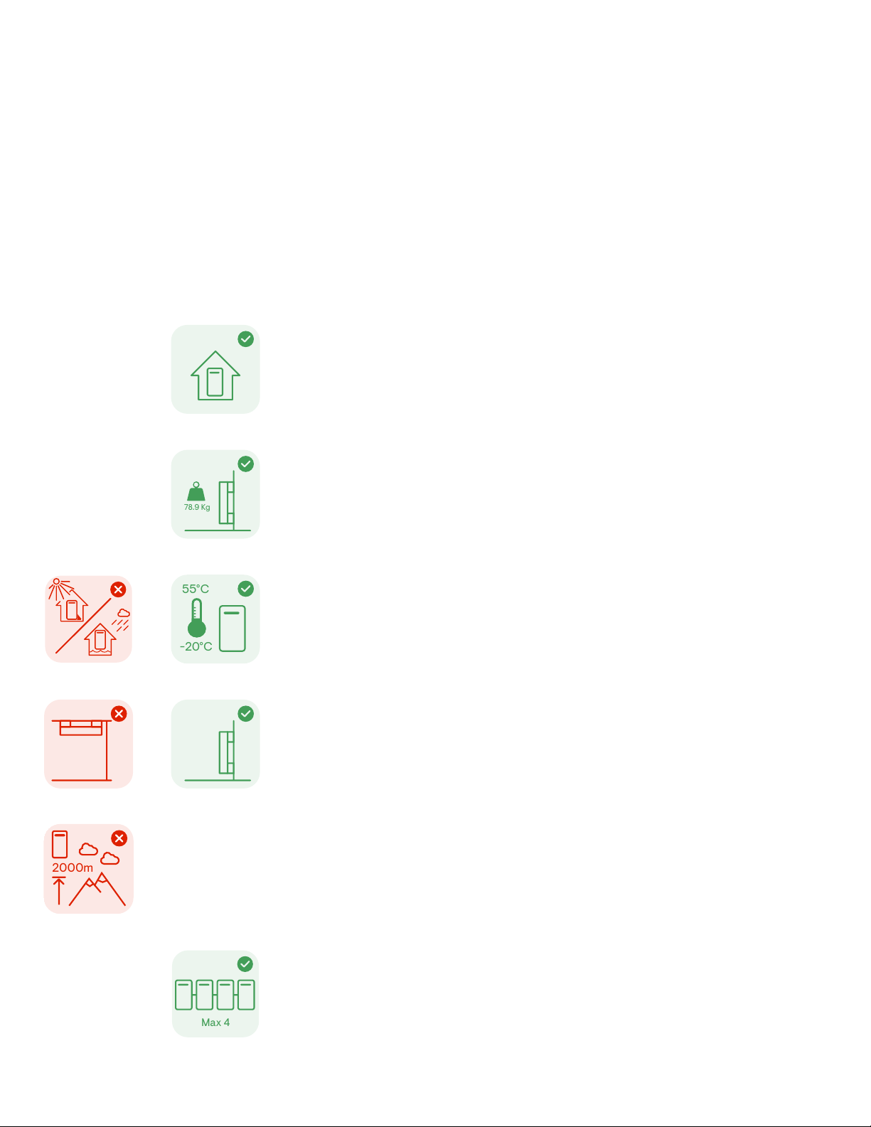
• The IQBattery 5P housing is IP55 rated and can be installed indoors or outdoors.
The terminal blocks accept copper conductors of 6 mm2to 30 mm2.
• Make sure the installed location can sustain the total weight of the IQBatteries and mounting bracket.
Total weight for IQBattery5P, including the IQBattery 5P unit, cover and wall-mount bracket, is 78.9 kg
(174 lbs). The wall must contain blocked studs that can bear the battery weight or can be of masonry or
other suitable structure.
• Make sure there are no pipes or electrical wires where you plan to drill.
• Follow local standards (AS/NZ5139) : Choose a well-ventilated location where the ambient temperature
and humidity are within −20°C to 55°C (−4°F to 131°F) and 5% to 95% relative humidity, non-condensing,
out of direct sunlight. The optimum ambient temperature range for installation location is 0ºC to 30ºC
(32ºF to 86ºF). Provide smoke alarms in the residence in accordance with building, re, and installation
codes.
• This product must not be installed at altitudes above 2,000 m.
• Follow all local standards and regulations set forth by the
Distributed Network Service Provider (DNSP).
• Up to four IQBattery5P units can be daisy chained on a single branch circuit.
IQSystemController
supports
up to a maximum of 80 A breaker for IQBattery 5P connection circuit.
• The maximum conductor size for IQBattery5P is 30 mm
2
and the maximum breaker rating with this
conductor size is 80 A.
Max 4
2000m
-20°C
55°C
78.9 Kg
• Consider the dimensions of the IQBatteries, easy access, height, and length of cable when selecting
the location.
• Select a location where you can interconnect IQBattery 5P to the IQSystemController.
8
IQ Battery 5P Quick Install Guide

Section A - Mounting the product
Step 1:
Minimum clearance
55 cm
98 cm
19 cm
The mounting instructions that follow are for the included wall-mount
bracket only. If you wish to install IQ Battery 5P in a oor-mount
conguration, order the pedestal accessory (B05-PM-0550-O) and
refer to the oor-mount instructions that come with that product.
This product must be installed with clearance at the left, right, top,
bottom, and front of the product as shown in the gure.
Keep IQBattery 5P away from falling or moving objects,
including motor vehicles.
NOTE: These are minimum manufacturer’s clearances.
Make sure to comply with all local compliance and regulation
standards.
91 cm
15 cm
15 cm
15 cm 15 cm
15 cm
If mounted in the path of a motor vehicle, Enphase
recommends a minimum mounting height of 91 cm (36 in)
above the oor.
For IQBatteries mounted at the same level, the minimum distance
between covers of two units can be up to 146 mm. Use the raceway
adapter (Enphase Accessory) between units only if the distance
between units is ≤ 165 mm (6.5 in).
9
IQ Battery 5P Quick Install Guide
Section A - Mounting the product
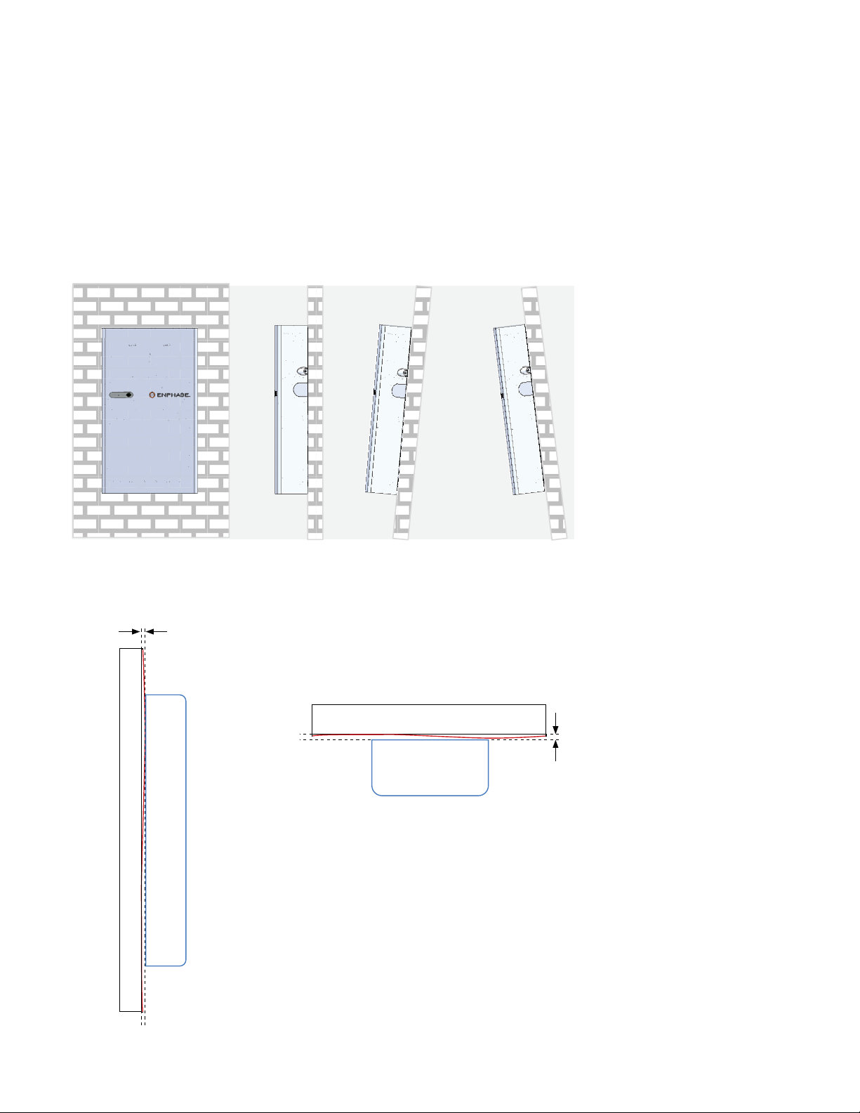
Step 2:
Mounting surface
1. Select a location where the tilt from vertical is less than 5° as
shown in the following image:
2. Make sure the mounting surface atness is within 2 mm
between boundary lines as shown in following image:
VERTICAL +5°INCLINATION -5°INCLINATION
NOTE: If the variation of the atness is more than
2 mm, the battery might not properly sit on
the wall-mount bracket through key holes. Use
spacers if the variation is more than 2 mm.
IQ Battery 5P
Side view
Top view
Mounting surface atness (across the unit installation height) shall be within 2 mm
Mounting surface should stay within indicated
2 mm gap between the boundary lines
IQ Battery 5P
Mounting wall
Mounting surface
2 mm
2 mm
10
IQ Battery 5P Quick Install Guide

Step 3:
Install the wall-mount bracket
Install the wall-mount bracket as per the following instructions:
1. Starting at installation position closest to the power source,
mark a levelline on the wall as a guide.
Multiple risks. Make sure not to drill into or attach to electric
wiring or pipes in the wall.
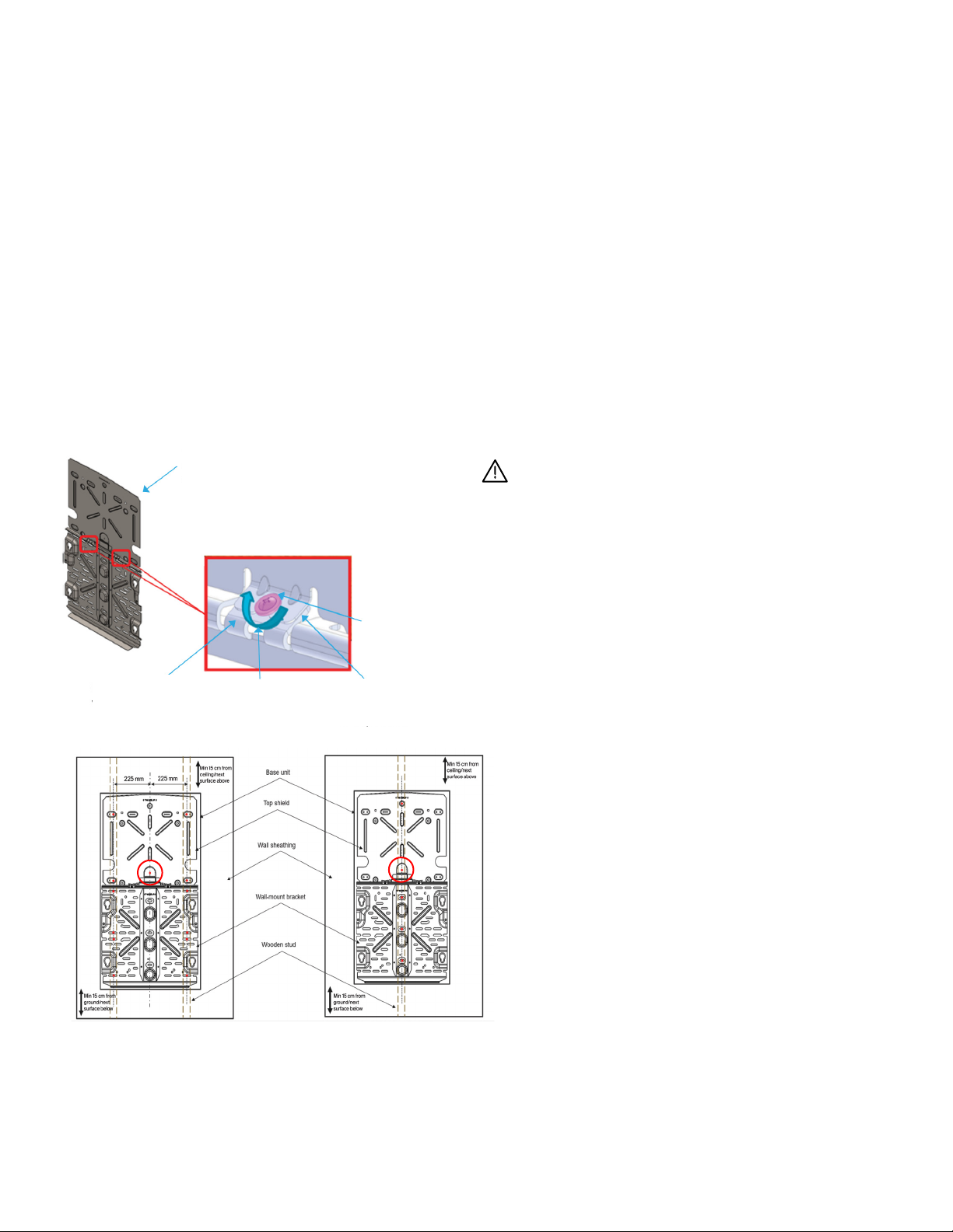
2. The wall-mount bracket comes in two parts: bottom bracket
that carries the weight of IQBattery 5P and the top shield that
covers the back of the IQBattery 5P.
Section A - Mounting the product
522 mm (20.5 in)
461 mm (18 in)
Two embosses with indentation
marks to provide exibility to
installers to x the top shield
Ten wall mounting
holes, marked ‘F’
F1 F2
F7 F8F5 F6
F3 F4
F9
F10
These two anges connect the top
shield to the bottom wall-mount
bracket
Top shield
Bottom mounting bracket
L1 L4L2 L3
The key holes are to mount the base
unit of IQBattery5P to the wall-mount
bracket and should not be used to
mount
the wall-mount bracket to the wall
Inclined slots for
pedestal assembly
Mounting slots
Locating features for
pedestal leg marked ‘L’
534 mm (21 in)
513 mm (20 in)
11
IQ Battery 5P Quick Install Guide
Section A - Mounting the product
Wall-mount sub assembly
(Wall-mount bracket + top shield)
Ground contact flange
of top shield
Ground contact flange
of wall-mount bracket
Tightening
direction
2x M4 grounding screws
(Torque to 1.5 N m)
Mounting on multiple
vertical studs
Mounting on single
vertical stud
NOTE: Ensure to always fasten the screw in the encircled hole.
3. Position the mounting bracket on the wall and fasten it using
the mounting slots.
4. Position the ground contact ange of the top shield on that of
the mounting bracket and align the screw slot/hole.
5. Fasten the top shield to the wall using the mounting holes as
shown below.
6. Fasten top shield to the mounting bracket at the ground
contact ange using two M4 screws (torque to 1.5 N m) to
complete the assembly.
7. Use M8 screws/lag bolts (or masonry attachments for
masonry wall) to attach the bracket using one screw/lag
bolt and washer for each slot (9.2 mm/0.36 in). Use minimum
of three screws/lag bolts for single stud mounting and four
screws/lag bolts for dual stud mounting. Tighten all screws to
manufacturer’s specied torque values.
8. Make sure the wall-mount bracket is solidly attached to the
wall.
9. Use minimum two M6 in screws for single stud mounting and
ve M6 in screws for dual stud mounting to fasten the top
shield to the wall.
Risk of injury and equipment damage. Do not mount an
IQBattery5P on a bracket that is not properly mounted.
12
IQ Battery 5P Quick Install Guide
Step 1:
Prepare to install IQBattery 5P
on mounting bracket
Section B
Installing IQBattery 5P
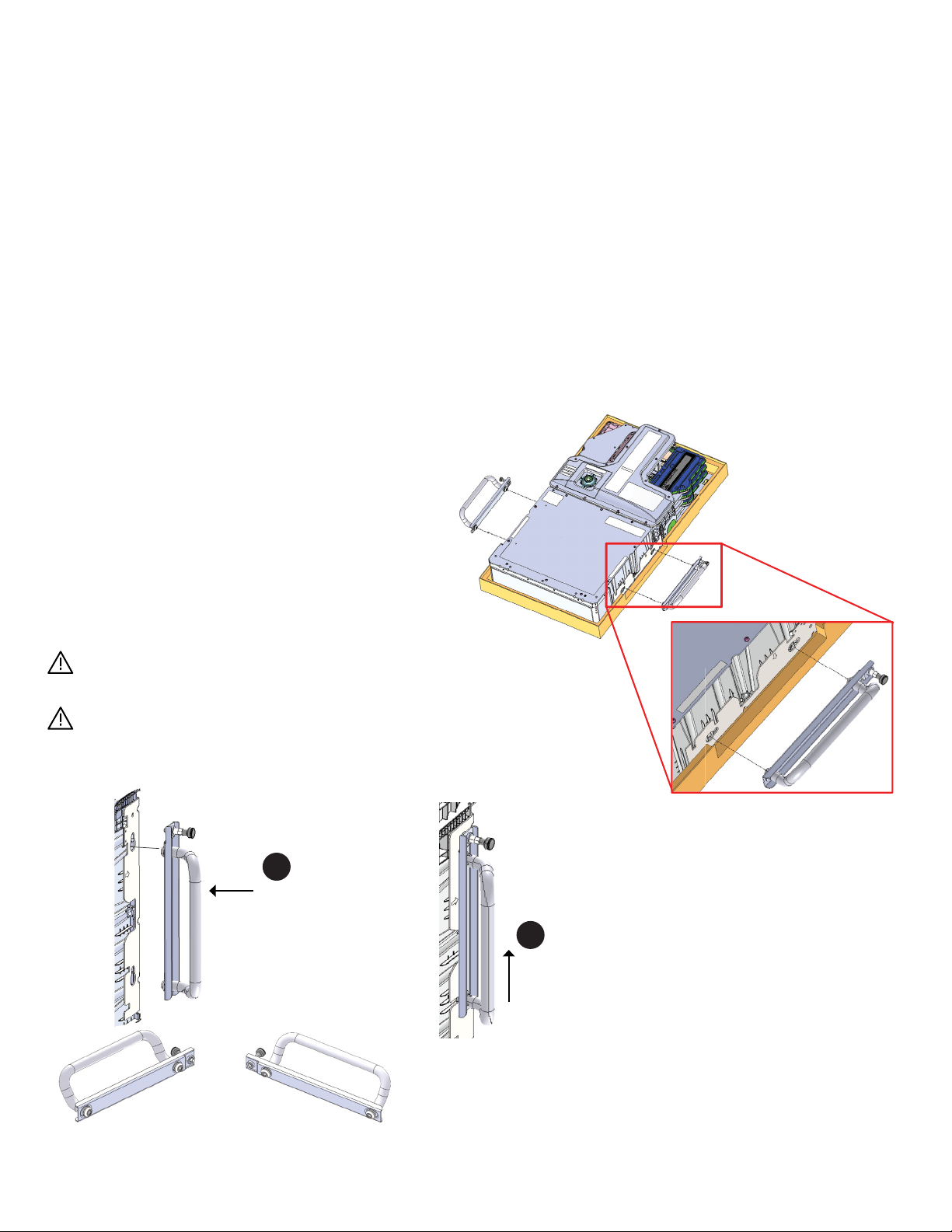
1. Remove the ID cover from the packaging and keep it aside.
2. Use the reusable lifting handles (sold separately) and check
that the plungers are extended and ready to engage into the
IQBattery5P slots.
3. Align left handle on left side of IQBattery5P and insert it into
the slots and slide towards the top of IQBattery5P enclosure
until it locks into place. Check that the handle is secure.
4. Repeat on the other side with the right handle.
Risk of injury and equipment damage. Two people are required
to lift IQBattery5P.
Lift IQBattery 5P from the packaging using the handles and
make sure the battery’s front side is facing towards you.
1. Insert
Position theHandleTubebolt
concentrictothe keyholeslots in the
backplate and insert the handle
2. Slide
Slidetillplunger locks
to holeinbackplate
LH RH
HandleTubebolt
Left handle Right handle
1. Insert
Position theHandleTubebolt
concentrictothe keyholeslots in the
backplate and insert the handle
2. Slide
Slidetillplunger locks
to holeinbackplate
LH RH
HandleTubebolt
Slide the handle up
until the plunger clicks
into place.
1. Insert
Position theHandleTubebolt
concentrictothe keyholeslots in the
backplate and insert the handle
2. Slide
Slidetillplunger locks
to holeinbackplate
LH RH
HandleTubebolt
Plunger
Hold the handle with the
plunger at the top, and insert
the handle into the keyhole
slots.
1
2
PlungerPlunger
13
IQ Battery 5P Quick Install Guide
Section B - Installing IQBattery 5P
5. Two persons together must lift the IQBattery5P unit from the
packaging using the handles and place it in upright position on
a at surface.
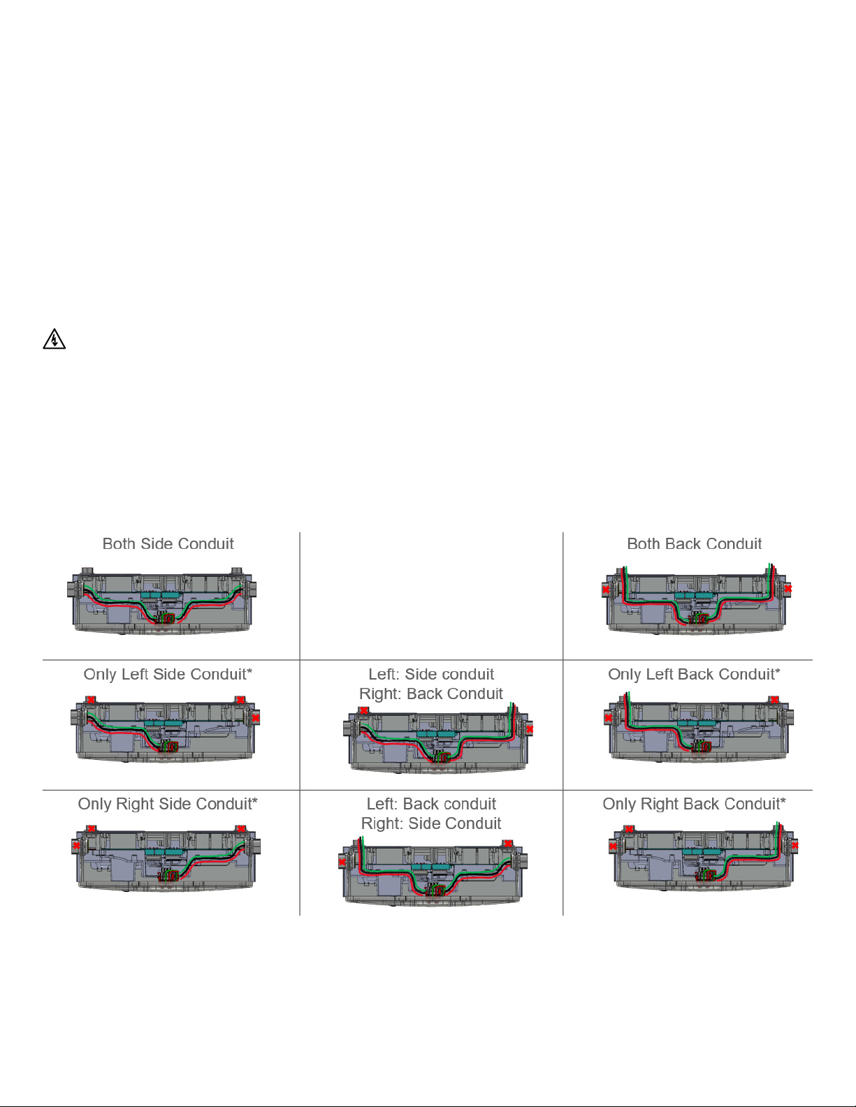
6. IQBattery5P can have the eld cable entry from back, left, or
right side. Finalize the side from where the eld cable enters
and leaves IQBattery5P. Use the following conguration image
to decide the cut-out for all the units.
Risk of electric shock. The DC control switch must be in the
OFF position before performing this step.
NOTE: The rear entry can support the conduit with diameter of
1/2 in (13 mm) to 3/4 in (19 mm) while side entry can support the
conduit with diameter of 1/2 in (13 mm) to 1-1/4 in (32 mm). Follow
manufacturer recommended instructions for conduit installation.
* One side conduit conguration is supported only if system has one IQBattery 5P or for the unit last in the daisy
chain farthest from the IQSystemController.
14
IQ Battery 5P Quick Install Guide

Section B - Installing IQBattery 5P
7. Open the front wiring cover by unfastening the 11 captive
screws (torque to 1.5 N m) from the wiring cover. Use electric
drive; do not use impact drives/impact drills.
15
IQ Battery 5P Quick Install Guide
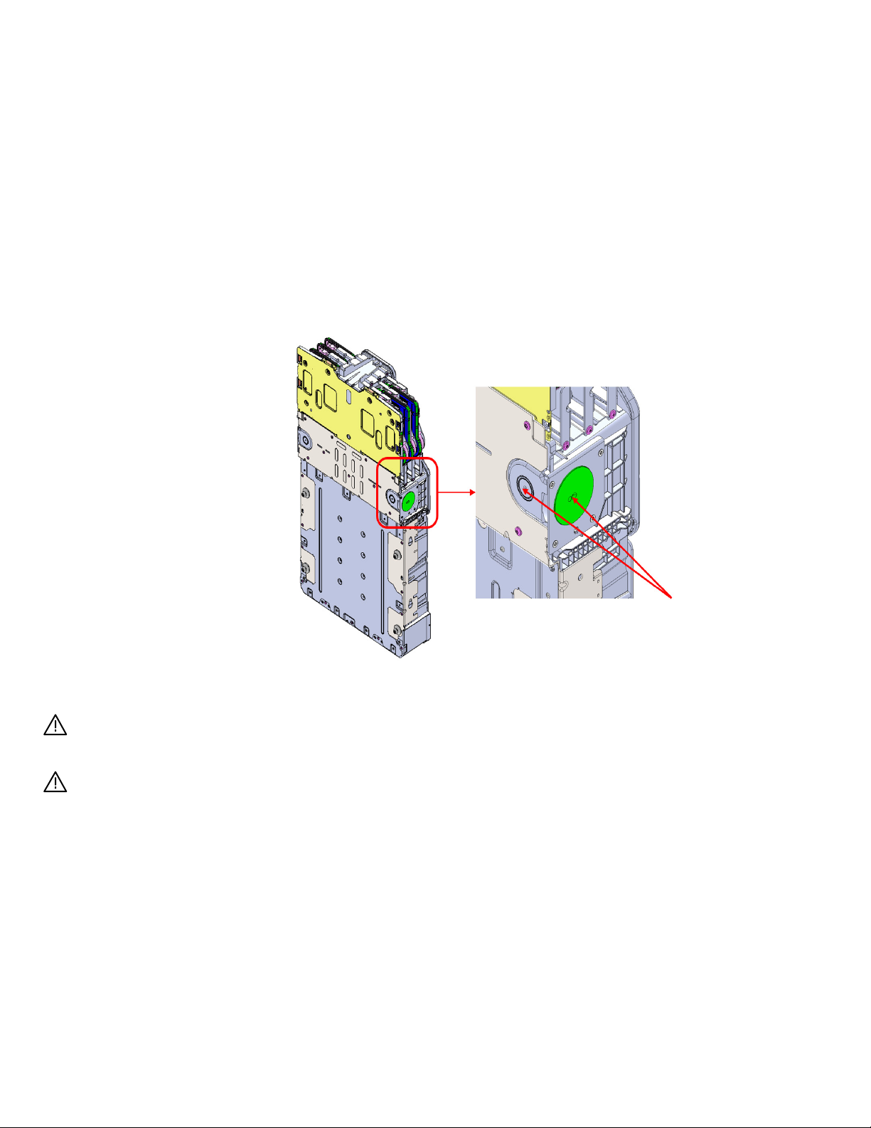
Ensure that drilling machine do not touch any internal
components or wall.
Ensure to clean the debris from inside the battery unit
after drilling.
8. Drill the appropriate cutout on either the back or side of the
unit or on both based on congurations. The rear entry can
support the conduit with diameter of 1/2 in (13 mm) to 3/4 in
(19 mm) while side entry can support the conduit with diameter
of 1/2 in (13 mm) to 1-1/4 in (32 mm). L and N terminals can
accept maximum cable size of 30 mm. GND terminal can
accpet maximum cable size of 10 mm.
Drill to appropriate cut-out
Section B - Installing IQBattery 5P
16
IQ Battery 5P Quick Install Guide
Section B - Installing IQBattery 5P
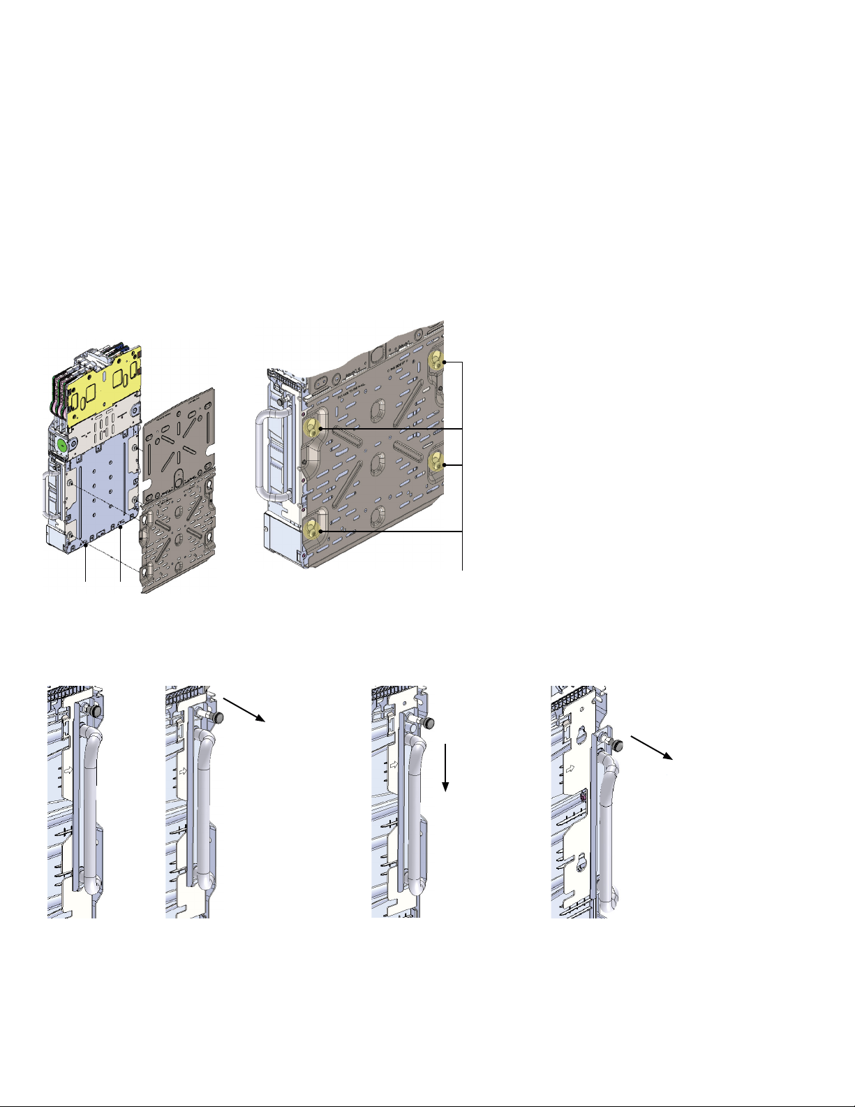
9. Hold the IQBattery5P straight, align, and insert four mount
bolts on the battery unit into the mounting bracket key holes
and slide it down.
NOTE: Use lift assist to avoid any mishap during lifting.
10. Remove installation handles.
Vents or drain holes Mount bolts
11. Secure the battery unit on the wall-mount bracket using two
3. Pull
Pull thehandleaway
from theunitto
remove it
1. Pull
Pull theplunger
outwardstounlockthe
handle
2. Slide
Slidethe
handle down
2. Slide
Slide the
handle
down
3. Pull
Pull the handle
away from the
unit to remove it
1. Pull
Pull the plunger
outwards to unlock
the handle
17
IQ Battery 5P Quick Install Guide

Section B - Installing IQBattery 5P
seismic screws (torque to 5.6 N m).
2x Seismic screws
2x Seismic screws
Vents or drain holes
The vent or drain holes provided at
the back of the unit serves the dual
purpose of natural ventilation and
condensation drainage. Blocking
these holes can aect the functionality
of the product.
18
IQ Battery 5P Quick Install Guide

Section B - Installing IQBattery 5P
1. Connect the following connectors to the BMS board in
following sequence:
i. B3: Temperature sense connector termination (black)
ii. B4: Battery Voltage sense connector termination
(multicolored)
iii. B1: Battery DC +ve connector termination
iv. B2: Battery DC -ve connector termination
v. CS1: Control switch intermediate connector termination
NOTE: There are two variants of control switch available in IQBattery5P. The control
switch cable is secured to wiring cover using cable ties. Select the control switch
available at site based on below images and cut the cable ties on the wiring cover to
access the control switch cable.
NOTE: Ensure that all the connectors are latched
properly and clicking sound is observed.
2. Fasten (torque to 1.5 N m) the 11 captive screws at the wiring
cover as shown. Use electric drive; do not use impact drives/
impact drills.
B3 B4
B1
B2
CS1
Step 2:
Prepare for eld wiring
Cut two cable ties and
insert the connector on
CS1 in BMS board
Cut one cable tie and
insert the connector on
CS1 in BMS board
19
IQ Battery 5P Quick Install Guide
Section C
Wiring
Install conduit/raceway
adapter and eld wiring
1. When installing a single IQBattery 5P unit, insert the conduit in
the cutouts drilled in previous step.
NOTE: Use a “chase nipple” & “rigid coupling” as spacer for
connecting 90° tting to the battery. This avoids interference
between the 90° tting and battery ID cover. Make sure the
joints are properly fastened and are watertight.
2. If installing more than one IQBattery 5P, insert the conduit
on the side of the unit closest to the AC disconnect. If an
IQSystemController is in line-of-sight, the breaker on
IQSystemController can service as the AC disconnect.
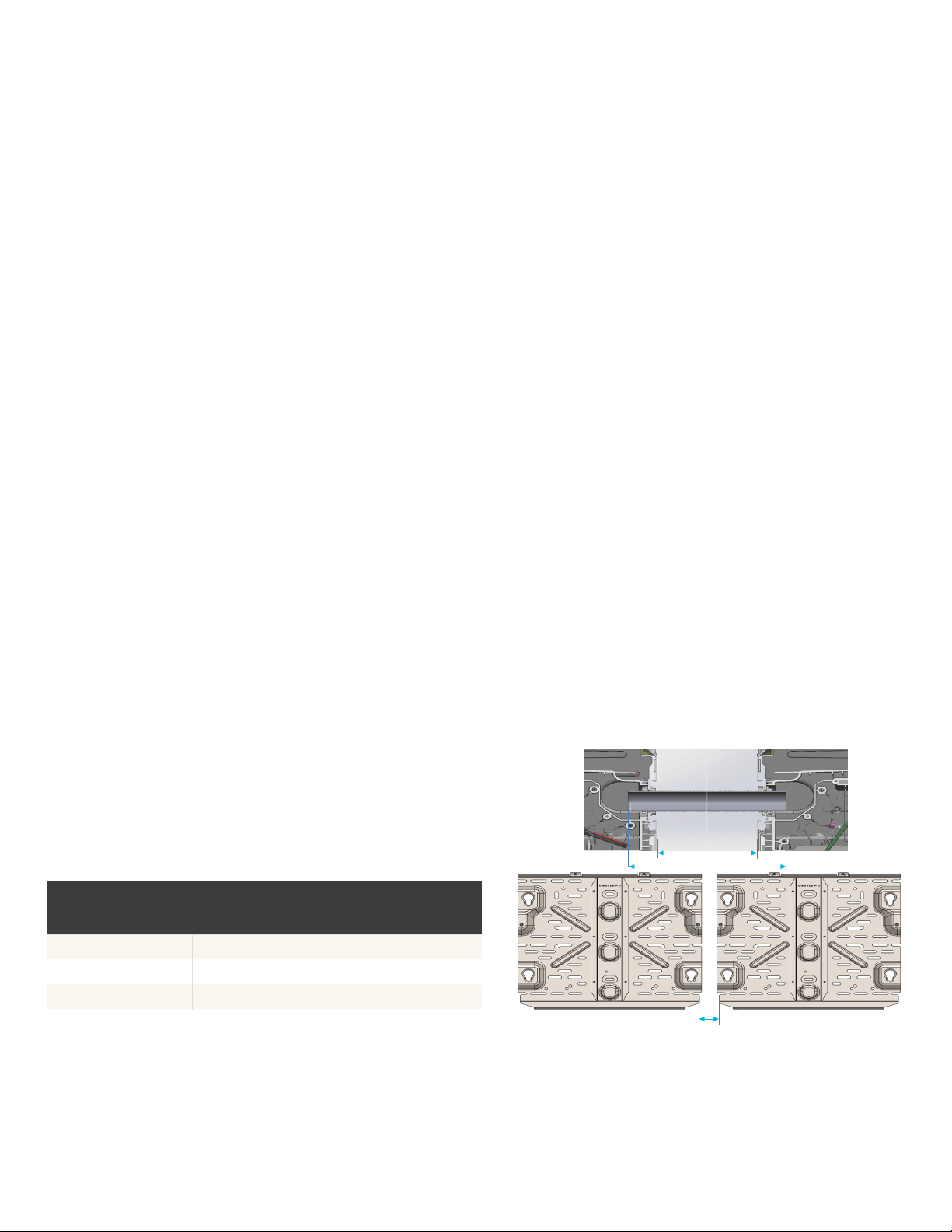
3. Use either raceway adapter or conduit in between the
IQBattery 5P units based on following:
• Use conduit between units if distance between units is > 165 mm
(6.5 in).
• Use a raceway adapter between units only if the distance
between units is ≤ 165 mm (6.5 in) and they are at the same
level. Raceway adapters can be provided by Enphase (sold
separately) and have the following conguration:
BATTERY SPACING
WITH COVER (A)
CORRECTED RACEWAY
ADAPTER LENGTH (B)
SPACING BETWEEN
WALL-MOUNT
BRACKETS (C)
165 mm (6.5 in) 220 mm (8.6 in) 181.1 mm (7.13 in)
152 mm (6.0 in) 220 mm (8.6 in) 168.4 mm (6.63 in)
146 mm (5.75 in) 220 mm (8.6 in) 162.05 mm (6.38 in)
B
A
C
20
IQ Battery 5P Quick Install Guide
Other manuals for IQ Battery 5P
3
Table of contents
Other enphase Batteries Pack manuals


