manuals.online logo
Brands
  1. Home
  2. •
  3. Brands
  4. •
  5. enphase
  6. •
  7. Gateway
  8. •
  9. enphase COMMS-KIT-INT-02 User manual

enphase COMMS-KIT-INT-02 User manual

QUICK INSTALL GUIDE
CONTENTS
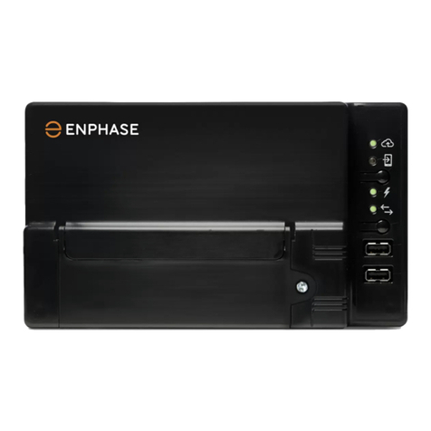
The Enphase Communications Kit 2 INT enables the IQ Gateway Metered
to communicate with the IQ Battery 5P. The device has a USB Type-C
port, two control cable ports, and a drain port.
The Communications Kit 2 INT includes the following accessories:
• One control header with termination resistor
• One control header without a resistor
• One USB Type-C to USB Type-A cable
• Zip-ties for cable management
• DIN rail adapters and screws
• Two spare control headers
The USB port connects the Communications Kit 2 INT to the IQ Gateway.
This enables communication between the device and the IQ Gateway.
The control headers must be installed on the control ports on the Com-
munications Kit 2 INT.
(Model: COMMS-KIT-INT-02)
Installing the Enphase Communications Kit 2 INT
The Enphase Communications Kit 2 INT (COMMS-KIT-INT-02) enables wired communication between IQ Gateway Metered and IQ Battery 5P using Control
(CTRL) cables.
Read and follow all warnings and instructions in this guide. Do not proceed if you do not fully understand any of the concepts, terminology, or hazards out-
lined in these instructions. These instructions are not meant to be a comprehensive guide to installing an IQ Battery 5P system. Use the IQ Battery 5P Quick
Install Guide along with this document to plan your installation. All installations must comply with local codes and standards.
Torque details of the control cable are given below:
DANGER! Risk of electric shock. All sources to equipment
being serviced must be disconnected external to the device.
Storage circuits must ALWAYS be isolated via a circuit breaker
or isolator switch before working on any part of the system.
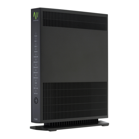
Figure 1: Front view of the Communications Kit 2 INT
© 2023 Enphase Energy. All rights reserved. Enphase, the e and CC logos, IQ, and certain other marks listed at
https://enphase.com/trademark-usage-guidelines are trademarks of Enphase Energy, Inc. in the US and other
countries. Data subject to change. Rev02/2023-09-05
INSTALLATION
Preparation
A ) Install the Communications Kit 2 INT in an IP3X or higher-rated en-
closure with adequate space for cable routing. It is recommended to
install both the IQ Gateway and the Communications Kit 2 INT in the
same enclosure.
B ) The enclosure should have access to an Earth terminal bar.
C ) Based on your installation design, identify if the Communications Kit 2
INT is a terminating node or a non-terminating node in the daisy chain of
devices connected via a control cable on the site. The installation proce-
dure varies accordingly, as described later in the document.
D ) Make sure the system is powered o before you begin the installation.
E ) Ensure that you have these tools and materials for the installation:
a. Torque terminal screwdrivers and wire stripper
b. Control cables
F ) Install the wired control headers on the unit. Refer to section 2, Wiring
the Communications Kit 2 INT.
G ) Connect the cable from the Earth bar to the PE port on the device.
H ) Connect the device to an IQ Gateway Metered with the USB cable
provided.
I ) Switch on the IQ Gateway Metered.
J ) The Communications Kit 2 INT can be installed in two ways. The box
ships with DIN rail adapters that can be connected to the device to
mount it on a DIN rail. The device can also be screwed into the back
wall of the enclosure using the screw points provided on extreme ends
on either side of the unit.
1
CABLE TYPE WIRE SIZE TORQUE
Control cables 0.34 mm20.2 N m
Ground cables 0.75 mm20.2 N m
Drain wire
(braided)
CTRL (G)
NA
CTRL (H)
CTRL (L)
8 mm
70 mm
120 mm
The tested and supported control cable make and model is
Belcom (manufacturer part number 4302P2254).
✓NOTE: Use a wire stripper to strip the jacket of the control communi-
cation cable.
Screw terminal for control
cable (torque 0.2 N m)
Drain wire
Drain terminal
CTRL header
• Ensure that both ends of the CTRL cable twisted pair conductors are
inserted into the header, as shown above.
• Connect the drain wire to the drain terminal only at one end of a
CTRL cable. Do not connect drain wires at both ends of a CTRL cable.
Follow the guidance based on section 3, Control (CTRL) wiring between
system components.
CTRL HEADER NUMBERS CTRL SIGNALS WIRE DESIGNATION
Screw terminal 1 CTRL L White with blue stripe
Screw terminal 2 CTRL H Blue with white stripe
Screw terminal 3 CTRL G White with orange stripe
Screw terminal 4 NA Orange with white stripe
Wiring the Communications Kit 2 INT
Strip the cable insulation as per the following image. Keep the termi-
nating resistor only on the devices that are on either end of the control
communication bus, and remove the resistor from all other devices.
Cable shield
2
Control (CTRL) wiring between system components
Control wiring guidance for installing IQ Battery 5P(s) with a Communications Kit 2 INT:
Refer to the following wiring sequences to understand the position of the header with termination resistor, wiring order, and drain wire termination location.
✓ NOTE: The total length of CTRL wiring across the system should not exceed 100 meters to ensure the system operates as per specications.
✓ NOTE: Ensure the following guidelines are followed to avoid failures during system commissioning:
• One header with termination resistor should be installed on the component located at each end of the control network.
• The drain wire should only be terminated on one end of control wiring between system components.
• It is recommended that the drain wire be terminated at the component from which the control wiring for the section is initiated.
3
The following table provides the mapping of the control communication signals to the wire colors for the recommended Belcom cables:
Cable shield
• To ensure proper control (CTRL) cable connection with IQ Batteries,
follow the guidelines outlined below while connecting the cable to
the headers.
WARNING! Failure to follow wiring guidance will result in the
system being unable to detect devices, leading to commis-
sioning and operation failures.
Following are the two common wiring sequences:
Sequence 1: Communications Kit 2 INT - IQ Battery 5P(s)
Termination
resistor
Sequence 2: IQ Battery 5P - Communications Kit 2 INT - IQ Battery 5P
Termination
resistor
The following table provides termination resistor locations for the above sequences:
CONTROL WIRING SEQUENCE TERMINATION RESISTOR LOCATION
Communications Kit 2 INT - IQ Battery 5P(s) • Communications Kit 2 INT
• Last IQ Battery 5P in the control bus
IQ Battery 5P(s) - Communications Kit 2 INT - IQ Battery 5P(s) • The two IQ Battery 5P's at each end of the control bus
The LED on the Communications Kit 2 INT indicates the connectivity status.
The various LED states are as follows:
Connecting to IQ Gateway software
The Communications Kit 2 INT needs IQ Gateway software version 8.2 or
higher to work with other Enphase Energy System components.
A ) Install the Enphase Installer App mobile application from iOS App
store or Android play store and log in to your Enphase account. With
this app, you can connect to the IQ Gateway to track system instal-
lation progress. You may also download the app from the Enphase
website at https://enphase.com/en-gb/installers/apps.
B ) Download the latest version of IQ Gateway software. To do so, go to
the Settings tab in the Enphase Installer App and tap the Update
Now button under IQ Gateway Software.
C ) After updating the IQ Gateway to version 8.2 or higher, scan the devic-
es to ensure they are identied as component of the Enphase Energy
System.
D ) Verify the devices are connected by navigating to:
Devices > IQ Battery > <serial number>
SAFETY
IMPORTANT SAFETY INSTRUCTIONS
SAVE THESE INSTRUCTIONS
Follow these important instructions during the installation and mainte-
nance of the Communications Kit 2 INT.
Safety and advisory symbols
+DANGER: This indicates a hazardous situation, which, if not avoided,
will result in death or serious injury.
*WARNING: This indicates a situation where failure to follow instruc-
tions may be a safety hazard or cause equipment malfunction. Use
extreme caution and follow instructions carefully.
*WARNING: For installation and use in a restricted access area by a
qualied and instructed personnel.
✓NOTE: This indicates information particularly important for optimal
system operation. Follow instructions carefully.
Safety instructions
+DANGER: Risk of electric shock. Risk of re. Only qualied personnel
should troubleshoot, install, or add parts to the IQ Gateway.
+DANGER: Risk of electric shock. Risk of re. Ensure that all wiring is
correct and that none of the wires are pinched or damaged.
✓NOTE: Do not attempt to repair the Communications Kit 2 INT. It con-
tains no user-serviceable parts. If the equipment fails, contact Enphase
Support for assistance or replacement equipment.
✓NOTE: Using unapproved attachments or accessories could result in
damage or injury.
Compliance with EU directives
This product complies with the following EU directives and can be used in the
European Union without any restrictions.
• Electro Magnetic Compatibility (EMC) directive 2014/30/EU
• Low Voltage Directive (LVD) 2014/35/EU
• Restriction of Hazardous Substances (RoHS) 2011/65/EU
RED directive compliance
Hereby, Enphase Energy Inc. declares that the radio equipment type
Communications Kit 2 INT follows Directive 2014/53/EU.
The full text of the EU declaration of conformity (DoC) is available at:
https://enphase.com/en-gb/installers/resources/documentation.
Manufacturer:
Enphase Energy Inc.,
47281 Bayside Pkwy., Fremont, CA,
94538, The United States of America, Ph: +1 (707) 763-4784
Importer:
Enphase Energy NL B.V.,
Het Zuiderkruis 65, 5215MV,
‘s-Hertogenbosch, The Netherlands, Ph: +31 73 3035859
Note for third-party products
Any third-party manufacturer or importer product(s) used to install or
commission Enphase product(s) shall comply with the applicable EU Directive(s)
and requirements in the European Economic Area (EEA). It is the responsibility of
the installer to conrm that all such products are labelled correctly and have the
required compliant supporting documentation.
Environmental protection
ELECTRONIC DEVICE: DO NOT THROW AWAY. Waste electrical
products should not be disposed of with household waste.
Proper disposal of batteries is required. Refer to your local codes for
disposal requirements.
Revision history
REVISION DATE DESCRIPTION
140-00332-02 September 2023 Safety instructions updated
140-00332-01 July 2023 Initial release
Enphase Support: https://enphase.com/contact/support
4
LED STATE EVENT
Red ERROR (control or BUS error)
Blinking green Communications Kit rmware update
Green Communications Kit is operational
Blue No USB communication
Other enphase Gateway manuals

enphase CT-100-SPLIT ROW User manual

enphase

enphase CT-100-SPLIT ROW User manual

enphase Envoy Communications Gateway User manual

enphase

enphase Envoy Communications Gateway User manual

enphase Envoy Communications Gateway User manual

enphase

enphase Envoy Communications Gateway User manual

enphase Gateway User manual

enphase

enphase Gateway User manual

enphase Enboy R Quick start guide

enphase

enphase Enboy R Quick start guide

enphase IQ System Controller 2 User manual

enphase

enphase IQ System Controller 2 User manual

enphase ENV-S-EM-230 User manual

enphase

enphase ENV-S-EM-230 User manual

enphase Envoy Communications Gateway User manual

enphase

enphase Envoy Communications Gateway User manual

enphase Envoy Communications Gateway User manual

enphase

enphase Envoy Communications Gateway User manual

enphase Envoy-S User manual

enphase

enphase Envoy-S User manual

enphase Envoy Communications Gateway User manual

enphase

enphase Envoy Communications Gateway User manual

enphase ENV-S-AM1-120 Instruction Manual

enphase

enphase ENV-S-AM1-120 Instruction Manual

enphase ENV-S-AM1-230-60 User manual

enphase

enphase ENV-S-AM1-230-60 User manual

enphase Envoy Communications Gateway User manual

enphase

enphase Envoy Communications Gateway User manual

enphase ENV-S-EM-230-LF-KIT User manual

enphase

enphase ENV-S-EM-230-LF-KIT User manual

enphase ENV-S-WM230 User manual

enphase

enphase ENV-S-WM230 User manual

enphase IQ Combiner 3C-ES User manual

enphase

enphase IQ Combiner 3C-ES User manual

enphase Envoy Communications Gateway User manual

enphase

enphase Envoy Communications Gateway User manual

enphase ENV-S-WM230 User manual

enphase

enphase ENV-S-WM230 User manual

enphase Envoy-S Standard ENV-S-WB-230-F User manual

enphase

enphase Envoy-S Standard ENV-S-WB-230-F User manual

enphase Envoy-S User manual

enphase

enphase Envoy-S User manual

enphase Envoy Communications Gateway User manual

enphase

enphase Envoy Communications Gateway User manual

enphase ENP-ENV-S-EM-230 Instruction Manual

enphase

enphase ENP-ENV-S-EM-230 Instruction Manual

enphase IQ8D User manual

enphase

enphase IQ8D User manual

Popular Gateway manuals by other brands

Eaton EG2-NA installation instructions
Eaton

Eaton EG2-NA installation instructions

Nectar Base Station manual
Nectar

Nectar Base Station manual
Dialogic Vision CX Video Administration manual
Dialogic

Dialogic Vision CX Video Administration manual

Browan WAPS-232N LW installation guide

Browan

Browan WAPS-232N LW installation guide

OpenVox WGW1002 user manual

OpenVox

OpenVox WGW1002 user manual

Opengear ACM5504-5-GS-I quick start guide

Opengear

Opengear ACM5504-5-GS-I quick start guide

ZyXEL Communications P-2302HWUDL-P1 Series user guide

ZyXEL Communications

ZyXEL Communications P-2302HWUDL-P1 Series user guide

AudioCodes Mediant 3000 user manual

AudioCodes

AudioCodes Mediant 3000 user manual

Huawei Echolife HG520b quick start guide

Huawei

Huawei Echolife HG520b quick start guide

D-Link DVG-7044S user manual

D-Link

D-Link DVG-7044S user manual

Rotronic RMS-GW-915 Short instruction manual

Rotronic

Rotronic RMS-GW-915 Short instruction manual

ZyXEL Communications EX3510-B1 user guide

ZyXEL Communications

ZyXEL Communications EX3510-B1 user guide

Thermokon SRC65 datasheet

Thermokon

Thermokon SRC65 datasheet

Eurotech ReliaGATE 10-10-00 user manual

Eurotech

Eurotech ReliaGATE 10-10-00 user manual

Lucent Technologies PacketStar PSAX 2300 user guide

Lucent Technologies

Lucent Technologies PacketStar PSAX 2300 user guide

IXXAT CANio 250 Quick start manual

IXXAT

IXXAT CANio 250 Quick start manual

ZyXEL Communications ZYAIR B-4000 Quick installation guide

ZyXEL Communications

ZyXEL Communications ZYAIR B-4000 Quick installation guide

Linksys WCG200 - Wireless-G Cable Gateway Wireless... Quick installation

Linksys

Linksys WCG200 - Wireless-G Cable Gateway Wireless... Quick installation

manuals.online logo
manuals.online logoBrands
  • About & Mission
  • Contact us
  • Privacy Policy
  • Terms and Conditions

Copyright 2025 Manuals.Online. All Rights Reserved.