manuals.online logo
Brands
  1. Home
  2. •
  3. Brands
  4. •
  5. ADTRAN
  6. •
  7. Gateway
  8. •
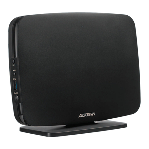
  9. ADTRAN jobAid+ Total Access 324 User manual

ADTRAN jobAid+ Total Access 324 User manual

1
jobAid
DESCRIPTION
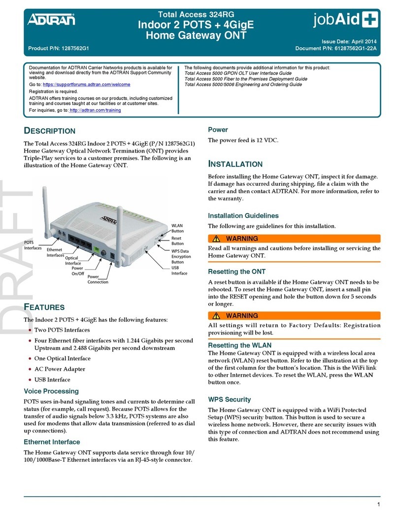
This Job Aid supports the Total Access 324 Indoor 3rd Generation
Single Family Unit (SFU) Optical Network Termination (ONT). The
illustration above displays the rear of the SFU ONT and a cut-away of
the top depicting status LEDs.
Ports/Connectors
■2 POTS Ports
■4 Gigabit Ethernet Ports
■DC Power Plug
■UPS Connector
■SC Fiber Connector (located behind the protector panel labeled
“Fiber Port”. Refer to “Installing Fiber” on page 2 for installation
information.)
Resetting the ONT
A reset button is available if the SFU ONT needs to be rebooted. To
reset the SFU ONT, press the RESET button for 5 seconds or longer.
WARNING
!
All settings will return to Factory Defaults: Registration provisioning
will be lost.
Voice Processing
POTS uses in-band signaling tones and currents to determine call
status (for example, call request). Because POTS allows for the
transfer of audio signals below 3.3 kHz, POTS systems are also used
for modems that allow data transmission (referred to as dial up
connections).
Total Access 324
Indoor 3rd Generation SFU ONT
Ethernet Interface
The SFU ONT supports data service through four 10/100/1000Base-T
Ethernet interfaces via an RJ-45-style connector.
Power
The power feed is 12 VDC. The total power consumption with 4
Ethernet Ports running and both POTS lines off-hook is approxi-
mately 7.2 Watts.
The SFU ONT uses a standard DC barrel-type connector as a primary
power source. A connection for an optional un-interruptible power
supply (UPS) is provided.
Fiber
Fiber is supplied to the SFU ONT using an SC Fiber connection
located behind a removable protective panel.
UPS
The SFU ONT provides an optional connection for a UPS. An UPS is a
battery backup system designed to continue providing power when
the primary power source is lost. Power is supplied to the SFU ONT
by a local power source with battery backup that utilizes the AC
power at the customer premises.
INSTALLATION
After unpacking the SFU ONT, inspect it for damage. If damage is
noted, file a claim with the carrier and then contact ADTRAN. For
more information, refer to the warranty.
Installation consists of positioning the SFU ONT either on a desktop
or wall mount, connecting POTS, Ethernet and Fiber, and connecting
power.
CLEI: BVMBN10F_ _
Product P/N: 1287735G3
Issue Date: April 2015
Document P/N: 61287735G3-22B
The following related online documents and resources provide additional information for this product:
Total Access 5000 Series Fiber to the Premises Deployment Guide
Total Access 5000/5006 Engineering Guide
ON/OFF PWR UPS
CLASS ONE
LASER
PRODUCT
POTS2 POTS1
LAN1 LAN2 LAN3 LAN4
RESET
PWR BAT LINK1 LINK2 LINK3 LINK4 POTS2 POTS1 LOS PON
PWR BAT POTS1 POTS2LAN2 LAN3 LAN4LAN1 LOS PON
Fiber Port
Documentation for ADTRAN Carrier Networks products is
available for viewing and download directly from the
ADTRAN Support Community website.
Go to:https://supportforums.adtran.com/welcome
Registration is required.
ADTRAN offers training courses on our products, including
customized training and courses taught at our facilities or at
customer sites.
For inquiries, go to: http://adtran.com/training
261287735G3-22B
2. Refer to the illustration below and connect the twisted-pair Tip
(green) and Ring (Red) to the RJ-11 connector using an RJ-11
crimper.
3. Insert the RJ-11 connector in the appropriate POTS 1 or POTS 2
jack.
Connecting Ethernet
The SFU ONT supports four 1 Gigabit (10/100/1000Base-T) connec-
tions (LAN 1 to LAN 4).
If Ethernet cables are not available, use the following procedure and
table to create the Ethernet cables:
1. Trim the insulation for the subscriber Ethernet cable.
2. Connect the wires per the following table using an RJ-45
Crimper.
3. Insert the CAT 6 rated cable in the appropriate LAN 1 through
LAN 4 ports.
Installing Fiber
CAUTION
!
LASER RADIATION
1300 nm to 1500 nm
Do not view directly with optical instruments.
This product contains a Class 1M Laser module that complies with 21
CFR 1040.10 and 1040.11 and IEC 60825-1 and -2.
Fiber is installed in an SC connecter located behind a removable
protector panel on the right-rear of the SFU ONT. Refer to the figure
below when installing fiber:
1. Remove the phillips-head screw from the right side of the fiber
protector panel.
2. Slide the protector cover back to expose the SC connector.
Ethernet RJ-45 Pin-out
Pin Name Description Color Code
1 TRD0+ Transmit/Receive Positive White/
Orange
2 TRD0- Transmit/Receive Negative Orange
3 TRD1+ Transmit/Receive Positive White/Green
4 TRD2+ Transmit/Receive Positive Blue
5 TRD2- Transmit/Receive Negative White/Blue
6 TRD1- Transmit/Receive Negative Green
7 TRD3+ Transmit/Receive Positive White/Brown
8 TRD3- Transmit/Receive Negative Brown
1 2 3 4
1 = Not Connected
2 = Tip
3 = Ring
4 = Not connected
Required tools
Standard technician tools and those listed below are required for
installing the SFU ONT:
■Carpenter’s level
■RJ-45/RJ-11 crimper
■A telephony/data communication test set
■PON power meter with wavelength filtering
■Fiberscope or videoscope
■Two #8 Pan Head screws (1 inch or greater in length)
■Assorted tie wraps for securing cabling and wiring
For fiber optic connections, the following are required:
■Fiber optical fusion splice tools
■ODC Fiber cleaning tool
■SC Fiber connector
Desk Top Installation
The SFU ONT can sit on a desktop or be wall mounted. With a desk
mount, ensure the SFU ONT is not located in direct sunlight and is
not located next to any thermal obstructions.
Wall Mount Installation
The SFU ONT can be wall-mounted.
NOTE
Refer to the illustration below when installing the SFU ONT on a wall
mount.
To wall mount the SFU ONT, perform the following steps:
1. Decide on a location for the SFU ONT.
2. Attach a 1/4 inch mounting board (typically plywood) to the
wall. If the wall is drywall construction, ensure the mounting
board is supported by the wall studs.
3. Install two #8 Pan Head screws (1 inch or greater in length)
using the key holes on the back of the SFU ONT as location
markers. Leave approximately 1/4 inch protruding from the
mounting surface.
4. Slide the SFU ONT over the Pan Head screws and exert a small
amount of downward pressure to ensure that the top of the
slots are resting on the shafts of the Pan Head screws.
Connecting POTS
If POTS cables are not available, use the following procedure to create
the POTS cables:
1. Trim the insulation for the subscriber POTS cables.
Rear of SFU ONT
61287735G3-22B 3
3. Clean the ends of the incoming fiber and the SC connection.
4. Connect the incoming fiber cable to the SC connection.
5. Route the fiber cable through the slot in the protective cover
and slide the it back in place.
6. Replace and secure the panel using the phillips-head screw.
Installing Power
Plug the supplied 12V AC/DC Power Converter into the PWR
connection on the rear of the chassis. Connect the power plug to a
standard 120 VAC outlet.
Using a UPS
The SFU ONT can typically use an un-interruptible power supply
(UPS) if desired. Power is supplied to the SFU ONT by a local power
source with battery backup that utilizes the AC power at the
customer premises. The UPS powers the SFU ONT and functions as a
BBU supplying continuous 12 VDC. Refer to the installation material
that is provided with the UPS when installing the BBU.
Connecting UPS
Connect the UPS to the 8-pin MOLEX connector labeled “UPS”
located on the rear of the SFU ONT chassis. The illustration below
represents the MOLEX connector on the rear of the ONT.
The UPS Power/Alarm Connections Table at the top on the next
column defines each pin on the connector.
NOTE
ADTRAN offers a UPS Cable assembly (P/N 1287402G1) for this
connector.
Protective
Cover
SC Connector
87 6 5
43
4321
UPS Power/Alarm Table
The following table indicates which pin is associated with each alarm
provided through a UPS connection.
ON/OFF Button
An On/Off button is located on the far-left side of the rear of the SFU
ONT. User functionality is limited to this button.
NOTE
If a BBU is being used and is disconnected, the SFU ONT is not
protected from power outages, and will send a “Battery Missing”
alarm to the OLT.
LED STATUS
The LEDs are located beneath the plastic housing and are only visible
after power has been applied. The following table provides the LED
status during normal operations.
Pin-Out Description Alarm
1 Power Input (+12 VDC) -
2UPSStatus-OnBattery1
3 UPS Status - Battery Missing 2
4 Signal Return -
5Power12VReturn-
6 UPS Status - Replace Battery 3
7 UPS Status - Low Battery 4
8 No Connection -
Label Status Indication
PWR 

Off
Green
AC or battery off
No Failure
BAT 

2
2
Off
Green
Green Flashing
Slow
Green Flashing Fast
ONT boot or battery missing/
not equipped
Battery equipped and no bat-
tery alarms present
Loss of AC, on battery
Battery low
LAN 1-4 

2
Off
Green
Green Flashing Fast
Link is down or not equipped
Link is up
Data is being sent or received
POTS 1-2 

2
Off
Green
Green Flashing
Slow
Unequipped or on-hook and
not ringing
Line is off-hook
Line in ringing state
LOS 

2
2
Off
Red
Red Flashing Slow
Red Flashing Fast
DS signal detected and is
within margins
No DS signal detected
DS signal is present but mar-
ginal
Software Upgrade failed
Warranty: ADTRAN will replace or repair this product within the warranty period if it does not
meet its published specifications or fails while in service. Warranty information can
be found online at www.adtran.com/warranty.
©2015 ADTRAN, Inc. All Rights Reserved. *61287735G3-22B*
REGISTRATION ID
There are two methods where the OLT will register the ONT:
■Serial Number Activation (performed by the OLT when the ONT
is “Discovered”)
■Set Registration ID Activation using Lineman’s handset (see
below)
Set Registration ID Activation
To set the Registration ID using a DTMF Keypad on a standard telco
Lineman’s handset, complete the following steps:
1. Verify the PON fiber-feed is disconnected from the ONT.
2. Press the RESET button on a previously powered-up ONT, or
perform an initial power-up on a new ONT.
3. Wait approximately one minute for the start-up to complete,
(PWR LED is ON and solid; LOS LED is ON and solid).
4. Attach the handset to the POTS Port 1 and go off-hook.
5. Observe that the reorder tone (fast busy) is generated.
NOTE
The Reorder tone is continuously played after going off-hook until
the valid Registration ID password is dialed. See Step 6.
6. On the keypad, dial the registration ID password: *123#.
7. Observe that the special information tone is generated.
NOTE
This is a fast “Hi-Mid--Low” tone that repeats.
8. On the keypad, press *to initiate the Registration ID input
sequence.
9. Observe that the special information tone stops.
10. Dial the remainder of the Registration ID sequence: 10digit
plus #.
NOTE
If the Registration ID entered is not valid, the Special Information
tone will be re-played. An incorrect Registration ID can be changed
by re-entering the Registration ID password (*123#) and then re-
entering a correct Registration ID sequence.
11. Wait 2 seconds. A confirmation tone is generated by the
handset. This indicates a valid Registration ID was entered.
12. Hang-up the handset.
13. Push the RESET button, or power-cycle the ONT.
14. Connect the fiber between the PON and ONT.
15. The ONT should begin Ranging with the new Registration ID.
The NET LED will be solid and the LOS LED will blink during
ranging. The NET and MGT LEDs will become solid and the
PON 

2
2
Off
Green
Green Flashing
Slow
Green Flashing Fast
ONT is not ranged
ONT is ranged
Ranging in progress
Software download in progress
Label Status Indication LOS LED will extinguish once the ONT has successfully
activated. This will take approximately 10-20 seconds.
16. Once the ONT has Ranged on the PON, the handset
Registration ID process is disabled.
NOTE
If AOE Auto Upgrade is active, a new ONT installation will be
detected and a fast blinking PON LED will indicate a new software
download has commenced. This may take 5 - 10 minutes to complete.
SPECIFICATIONS
Refer to the following for a list of all specifications for the Indoor SFU
ONT.
■Electrical
♦Voltage: 12 Volts typical
♦Minimum Voltage: 10 Volts
♦Maximum Voltage: 13.9 Volts
♦Power Consumption: Typical 7.2 watts
■Physical
♦10.0 inches wide (25.5 centimeters)
♦5.9 inches deep ((15.0 centimeters)
♦1.5 inches high (3.7 centimeters)
♦Weight: 1 pounds (0.45 kilograms)
■Environmental
♦Operational Temperature: 23°F to +113°F (–5°C to +45°C)
♦Storage Temperature: –40°F to 185°F (–40°C to +85°C)
♦Relative Humidity: 90%, noncondensing
■Optical
♦TX min power: 0.5 dBm
♦TX max power: 5.0 dBm
♦RSSI max sensitivity: -27 dBm
♦RX overload: -8 dBm
♦TX wavelength: 1310 nm typical
♦RX wavelength: 1490 nm typical
MAINTENANCE
The Indoor 3rd Generation SFU ONT does not require routine
hardware maintenance for normal operation. ADTRAN does not
recommend that repairs be attempted in the field. Repair services
may be obtained by returning the defective unit to ADTRAN. Refer to
the warranty for further information. Field support for software is
provided through upgrade facilities.
SAFETY AND REGULATORY COMPLIANCE
Refer to the Total Access 300 Series Indoor 3rd Generation SFU ONT
Safety and Regulatory Compliance Notice (61287735G3-17) for detailed
safety and regulatory information.
C A U T I O N
C A U T I O N
!
SUBJECT TO ELECTROSTATIC DAMAGE
OR DECREASE IN RELIABILITY.
HANDLING PRECAUTIONS REQUIRED.
ADTRAN CUSTOMER CARE:
From within the U.S. 1.800.726.8663
From outside the U.S. +1 256.963.8716
PRICING AND AVAILABILITY 1.800.827.0807
This manual suits for next models

1

Other ADTRAN Gateway manuals

ADTRAN Total Access 916 Manual

ADTRAN

ADTRAN Total Access 916 Manual

ADTRAN BroadCloud User manual

ADTRAN

ADTRAN BroadCloud User manual

ADTRAN SR820ac User manual

ADTRAN

ADTRAN SR820ac User manual

ADTRAN 617600139-13A User manual

ADTRAN

ADTRAN 617600139-13A User manual

ADTRAN TOTAL ACCESS 234 User manual

ADTRAN

ADTRAN TOTAL ACCESS 234 User manual

ADTRAN SmartRG SR400ac User manual

ADTRAN

ADTRAN SmartRG SR400ac User manual

ADTRAN NetVanta 1355 User manual

ADTRAN

ADTRAN NetVanta 1355 User manual

ADTRAN NetVanta 6360 Manual

ADTRAN

ADTRAN NetVanta 6360 Manual

ADTRAN NetVanta 644 User manual

ADTRAN

ADTRAN NetVanta 644 User manual

ADTRAN 841-t6 User manual

ADTRAN

ADTRAN 841-t6 User manual

ADTRAN SMART/RG SR501n User manual

ADTRAN

ADTRAN SMART/RG SR501n User manual

ADTRAN SDX810-RG User manual

ADTRAN

ADTRAN SDX810-RG User manual

ADTRAN NetVanta 644 User manual

ADTRAN

ADTRAN NetVanta 644 User manual

ADTRAN jobAid+ Total Access 311 User manual

ADTRAN

ADTRAN jobAid+ Total Access 311 User manual

ADTRAN NetVanta 644 Manual

ADTRAN

ADTRAN NetVanta 644 Manual

ADTRAN Total Access 908e Manual

ADTRAN

ADTRAN Total Access 908e Manual

ADTRAN SR905acv User manual

ADTRAN

ADTRAN SR905acv User manual

ADTRAN 424RG ONT User manual

ADTRAN

ADTRAN 424RG ONT User manual

ADTRAN Total Access 912 User manual

ADTRAN

ADTRAN Total Access 912 User manual

ADTRAN 834-v6 User manual

ADTRAN

ADTRAN 834-v6 User manual

ADTRAN 617600132F1-13A User manual

ADTRAN

ADTRAN 617600132F1-13A User manual

ADTRAN SR700ac User manual

ADTRAN

ADTRAN SR700ac User manual

ADTRAN jobAid 424RG3 User manual

ADTRAN

ADTRAN jobAid 424RG3 User manual

ADTRAN NetVanta 6355 Owner's manual

ADTRAN

ADTRAN NetVanta 6355 Owner's manual

Popular Gateway manuals by other brands

RTA 460ETCBMS-N700 Product user guide

RTA

RTA 460ETCBMS-N700 Product user guide

SMSEagle NXS-9750-3G user manual

SMSEagle

SMSEagle NXS-9750-3G user manual

B+B SmartWorx SmartSwarm 342 Quick start guides

B+B SmartWorx

B+B SmartWorx SmartSwarm 342 Quick start guides

Vimar Eikon quick start guide

Vimar

Vimar Eikon quick start guide

Allied Telesis AT-RG600 series Software reference manual

Allied Telesis

Allied Telesis AT-RG600 series Software reference manual

Lantronix FOX3-2G Series quick start

Lantronix

Lantronix FOX3-2G Series quick start

Sierra Wireless oMG 2000 installation guide

Sierra Wireless

Sierra Wireless oMG 2000 installation guide

ZyXEL Communications P-661HNU Series brochure

ZyXEL Communications

ZyXEL Communications P-661HNU Series brochure

MaxLong MG8322 user manual

MaxLong

MaxLong MG8322 user manual

NETGEAR D2200D-1FRNAS user manual

NETGEAR

NETGEAR D2200D-1FRNAS user manual

Teltonika TRB245 quick start guide

Teltonika

Teltonika TRB245 quick start guide

ZIGBEE BEGA CONTROL 70588 quick start guide

ZIGBEE

ZIGBEE BEGA CONTROL 70588 quick start guide

AudioCodes Mediant 1000B user manual

AudioCodes

AudioCodes Mediant 1000B user manual

aconno RootMeBaby user guide

aconno

aconno RootMeBaby user guide

ETC Net3 Four Port Gateway Setup guide

ETC

ETC Net3 Four Port Gateway Setup guide

ICP DAS USA DGW-521 quick start guide

ICP DAS USA

ICP DAS USA DGW-521 quick start guide

Riverside Hydronics ProtoNode manual

Riverside Hydronics

Riverside Hydronics ProtoNode manual

Cisco Linksys WAG200G user guide

Cisco

Cisco Linksys WAG200G user guide

manuals.online logo
manuals.online logoBrands
  • About & Mission
  • Contact us
  • Privacy Policy
  • Terms and Conditions

Copyright 2025 Manuals.Online. All Rights Reserved.