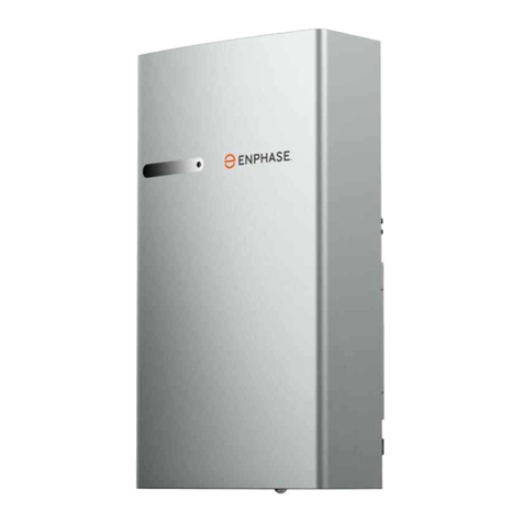
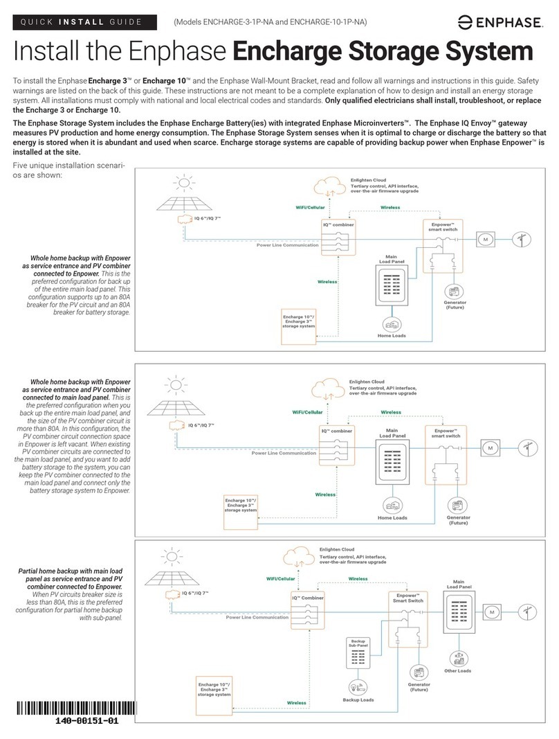
enphase IQBattery 5 User manual

QUICK INSTALL GUIDE (Model IQBATTERY-5P-1P-ROW)
Installing the IQ Battery 5
To install the Enphase IQ Battery 5 and the wall-mount bracket, read and follow all warnings and instructions in this guide. Safety warnings are listed at the
end of this guide. These instructions are not meant to be a complete explanation of how to design and install an energy storage system. All installations must
comply with national and local electrical codes and standards.
The IQ Battery system includes the battery cellpack with integrated IQ Microinverters and battery management system (BMS). The system requires
IQ System Controller for grid-tied and backup operations. The IQ Gateway inside IQ System Controller measures PV production, IQ Battery charge/discharge
power and home energy consumption, and it senses when it is optimal to charge or discharge the battery so that energy is stored when it is abundant and
used when it is scarce.
© 2023 Enphase Energy. All rights reserved. Enphase, the e and CC logos, IQ, and certain other marks listed at
https://enphase.com/trademark-usage-guidelines are trademarks of Enphase Energy, Inc. in the US and other countries.
Data subject to change. Rev 02
A. PREPARATION
A ) Make sure you have the following required Enphase items:
• One or more Enphase IQ Battery 5 and one IQ System Controller with
microgrid interconnect device (MID) functionality.
• The Enphase IQ Battery system requires an Internet connection
through the IQ Gateway in the IQ System Controller. Failure to maintain
an Internet connection may have an impact on the warranty.
See enphase.com/warranty for full terms.
• The IQ Battery and IQ System Controller are all connected to IQ
Gateway and communicate using communication control cables. The
Enphase PV system communicates to IQ Gateway using PLC.
B ) Make sure you also have the following required items:
• Mounting location that is structurally suited to bear the weight of the
IQ Battery. Total weight for the IQ Battery 5, including the IQ Battery
unit, cover, and wall-mount bracket, is 78.9 kg (174 lbs).
✓ NOTE: The wall must contain blocked studs that can bear the
battery weight or can be of masonry or other suitable structure.
• Tools: Conduit (with ttings and tting tools), drill, 4 mm pilot bit,
screwdriver, socket wrench, torque wrench, level, wire stripper, and
stud nder if installing on studs.
• Fasteners for wall-mount bracket and pedestal. Slots are 9.2 mm (0.36
in) for wall mount and 11.2 mm (inclined slots) for pedestal. Check with
a structural engineer and local standards for requirements.
• M8 lag bolts or screws: A minimum of three for single stud mounting and
four for dual stud mounting are required to mount the bracket on the wall.
• M6 screws: A minimum of two for single stud mounting and four for
dual stud mounting to fasten the top shield to the wall.
• Washers for use between fastener heads and wall-mount bracket.
• Copper conductors: 6 mm² to 30 mm² (11 mm (7/16 in) strip length)
copper conductors (rated at 90°C) for terminals.
• Control communications cables: Use Enphase recommended
cables, headers and also refer to local codes for any specic local
requirements.
• Conduit ttings: 20 mm, 25 mm or 32 mm (left and/or right side)
terminators are required for all installations, and IP55 conduit ttings
(terminators/raceway adapters) are needed when installing outdoors.
Enphase provides raceway adapters (sold separately) of varied lengths
as mentioned in later sections.
• Over current protection:The overcurrent protection in IQ Battery is not
branch circuit overcurrent protection and cannot be relied upon for
that purpose. The branch circuit overcurrent protection is located in IQ
System Controller or, when combining, in a separate combiner. See the
Enphase IQ System Controller Quick Install Guide for more information.
• Personal protective equipment (PPE) for handling lithium batteries as
required by local safety standards.
• Protective gloves for protection against sharp edges.
C ) Verify that main service is 230 V L-N.
✓ NOTE: The rated energy capacity of the battery is 4.96 kWh.
D ) Install the PV system and storage circuits into the IQ System Controller
as directed by the Enphase installation manuals.
B. UNBOXING THE IQ BATTERY 5
A ) Before you unbox the IQ Battery, check the “Energize By” label on the
shipping box to verify that the IQ Battery(ies) will be installed by the date
shown. If the date has passed, contact your distributor for next steps.
B ) Remove the upper packaging cover and follow the steps as shown in the
following image:
C ) Inspect the packaging and the IQ Battery(ies) for any signs of damage,
such as cracks, dents, or electrolyte leaks. Do not install or use the IQ
Battery(ies) if it has been dropped or damaged in any way. If damaged,
contact your distributor for replacement.
D ) Make sure your kit includes the following IQ Battery components:
• One IQ Battery 5
• One ID cover, two conduit covers
• One mounting bracket
• One top shield
*WARNING: Risk of injury. Take care when lifting. The IQ Battery unit is
heavy (66.25 kg/146.05 lbs) and requires two people to lift it.
1
2
34
5
67
8
9
10
11
12
Scheduled for Q2 2023 release

Plan a location for the IQ Batteries
The IQ Battery housing is IP55 rated and can be installed indoors or outdoors. The
terminal blocks accept copper conductors of 6 mm² to 30 mm².
A ) Following local standards: Choose a well-ventilated location where the
ambient temperature and humidity are within −20°C to 55°C (−4°F to 131°F)
and 5% to 95% RH, non-condensing, preferably out of direct sunlight. The
optimum ambient temperature range for installation location is 0ºC to
30ºC (32ºF to 86ºF). Provide smoke alarms in the residence in accordance
with building, re, and installation codes.
✓ NOTE: The IQ Battery location must be compliant to local standards
and regulations (AS/NZ5139).
B ) Make sure the mounting location can sustain the total weight of the IQ
Batteries and mounting bracket. Total weight for the IQ Battery 5, including
the IQ Battery unit, cover and wall-mount bracket, is 78.9 kg (174 lbs).
C ) Plan the mounting location to be at least 15 cm (6 in) off the ground and
from the ceiling. Keep the IQ Battery away from falling or moving objects,
including motor vehicles.
*WARNING: If mounted in the path of a motor vehicle, we recommend
a mounting height that is minimum 91 cm (36 in) above the oor.
✓ NOTE: Wherever local codes allow a smaller separation distance for
Energy Storage installations, the minimum spacing around
IQBattery 5 MUST be at least 15 cm (6 in) from the top, bottom, left,
and right side of the product.
D ) Select a location where the tilt from vertical is less than 5° as shown in the
following image:
E ) Make sure the mounting surface atness is within 2 mm between boundary
lines as shown in following image:
✓ NOTE: If the variation of the atness is more than 2 mm, the battery
might not properly sit on the wall-mount bracket through key holes.
Use spacers if the variation is more than 2 mm.
F ) Make sure there are no pipes or electrical wires where you plan to drill.
G ) Plan to maintain at least 914 mm (36 in) of clearance in front of each IQ
Battery.
H ) Consider the dimensions of the IQ Batteries, easy access, height, and
length of cable when selecting the location.
I ) Select a location where you can interconnect IQ Battery to the
IQ System Controller.
J ) Follow all local standards and regulations set forth by Distributed
Network Service Provider (DNSP).
K ) Up to four IQ Battery 5 units can be daisy chained on a single branch
circuit. IQ System Controller supports up to a maximum of
80 A breaker for IQ Battery connection circuit.
L ) The maximum conductor size for IQ Battery 5 is 30 mm² and the
maximum breaker rating with this conductor size is 80 A.
Prepare to install the wall-mount bracket
A ) Starting at installation position closest to the power source, mark a level
line on the wall as a guide.
* WARNING: Multiple risks. Make sure not to drill or attach into
electric wiring or pipes that are in the wall.
B ) The wall-mount bracket comes in two parts- bottom bracket that carries
the weight of the IQ Battery and the top shield that covers the back of the
IQ Battery.
Top shield
(28.8)
Side view
(49.86)
513.38 mm (20.21 in)
534 mm (21 in)
9.2 mm
Mounting slots
Base unit mounting
key holes
Inclined slots for
pedestal assembly
Locating features for
pedestal leg marked ‘L’
Ground contact flanges for top
shield
4x
Φ
11.2
L4
L3
L2
L1
Approximate weight: 4.75 kg/10.47 lbs
The key slots highlighted are to mount the
base unit of IQ Battery 5 to the wall-mount
bracket and should not be used to mount the
wall-mount bracket to the wall
2
C. INSTALLATION
1
VERTICAL +5°INCLINATION -5°INCLINATION
IQ Battery5
Mounting surface should stay within indicated 2 mm gap between the boundary lines
Mounting surface flatness (across the unit installation height) shall be within 2 mm
IQ Battery 5
Mounting Surface
2
522mm (20.5 in)
461 mm (18.15 in)
2x groundcontact flangestoconnectwithbottom
wall-mount bracket
10xwallmountingholes marked ‘F’
2x embosseswithindentationmarks
to provideflexibilitytothe installers to
fixtop shield to thewooden wall
Side view
(15.7)
F1 F2 F3 F4
F5 F6
F9
F7 F8
F10
2

C ) Position the mounting bracket on the wall and fasten it using the
mounting slots:
D ) Position the ground contact ange of the top shield on that of the
mounting bracket and align the screw slot/hole.
E ) Fasten the top shield to the wall using the mounting holes shown below.
F ) Fasten top shield to the mounting bracket at the ground contact ange
using two M4 screws (torque to 1.5 N m) to complete the assembly.
G ) Use M8 screws/lag bolts (or masonry attachments for masonry wall)
to attach the bracket using one screw/lag bolt and washer for each slot
(9.2 mm/0.36 in). Use minimum of three screws/lag bolts for single stud
mounting and four screws/lag bolts for dual stud mounting. Tighten all
screws to manufacturer’s specied torque values.
H ) Make sure the wall-mount bracket is solidly attached to the wall.
I ) Use minimum two M6 screws for single stud mounting and four M6
screws for dual stud mounting to fasten the top shield to the wall.
* WARNING: Risk of injury and equipment damage. Do not mount an
IQ Battery 5 on a bracket that is not properly mounted.
Prepare to install IQ Battery on mounting bracket
A) Remove the ID cover from the packaging and keep it aside.
B ) Use the lifting handles (sold separately) and check that the plungers are
extended and ready to engage into the IQ Battery 5 slots.
C ) Align left handle on left side of the IQ Battery 5 and insert it into the slots
and slide towards the top of the IQ Battery 5 enclosure until it clicks into
place. Check that the handle is secure.
D ) Repeat on the other side with the right handle.
* WARNING:
• Risk of injury and equipment damage. Two persons are required to lift
the IQ Battery 5.
• Lift the IQ Battery from the packaging using the handles and make sure
the battery’s front side is facing towards you.
3
E ) Two persons together must lift the IQ Battery 5 unit from the packaging
using the handles and place it in upright position on a at surface.
F ) The IQ Battery 5 can have the eld cable entry from back, left, or right side.
Finalize the side from where the eld cable enters and leaves the IQ Battery 5.
Use the following conguration image to decide the cut-out for all the units.
+ DANGER Risk of electric shock. The DC control switch must be in the
OFF position before performing this step.
✓ NOTE: The rear entry can support the conduit with diameter of 1/2 in
(13 mm) to 3/4 in (19 mm) while side entry can support the conduit with
diameter of 1/2 in (13 mm) to 1-1/4 in (32 mm). Follow manufacturer
recommended instructions for conduit installation.
* One side conduit conguration is supported only if system has only one
IQ Battery or for the unit last in the daisy chain farthest from the
IQ System Controller.
3
450 mm stud spacing Single stud
1. Insert
Position theHandleTubebolt
concentrictothe keyholeslots in the
backplate and insert the handle
2. Slide
Slidetillplunger locks
to holeinbackplate
LH RH
HandleTubebolt
Wall-mount sub assembly
(Wall-mount bracket + top shield)
Ground contact flange
of top shield
Ground contact flange
of wall-mount bracket
Tightening
direction
2x M4 grounding screws
(Torque to 1.5 N m)
3

G ) Open the front wiring cover by unfastening the 11 captive screws (torque
to 1.5 N m) from the wiring cover. Use electric drive; do not use impact
drives/impact drills.
H ) Drill the appropriate cutout on either the back or side of the unit or on
both based on congurations. The rear entry can support the conduit
with diameter of 1/2 in (13 mm) to 3/4 in (19 mm) while side entry can
support the conduit with diameter of 1/2 in (13 mm) to 1-1/4 in (32
mm). Use the table to decide the cutout diameter and the conductor size
required for line, neutral, and ground.
IQ Battery installa-
Recommended
wire mm2
> 60 cm (24 in)
L & N GND W/CTRL* W/CTRL*
Single unit 6 mm210 mm220 mm conduit 20 mm conduit
2 units daisy chaining 10 mm210 mm220 mm conduit 20 mm conduit
3 units daisy chaining 25 mm210 mm225 mm conduit 20 mm conduit
4 units daisy chaining 25 mm210 mm225 mm conduit 25 mm conduit
* Calculations based on Enphase recommended control communication cables (CTRL)
with outside diameter ≤ 10 mm
* WARNING: Ensure that drilling machine do not touch any internal
components or wall.
* WARNING: Ensure to clean the debris from inside the battery unit after
drilling.
I ) Bring the IQ Battery 5 unit to the already mounted wall-mount bracket.
J ) Hold the IQ Battery straight, align, and insert 4 mount bolts on the battery
unit into the mounting bracket key holes and slide it down.
K ) Remove installation handles.
L ) Secure the battery unit on the wall-mount bracket using two seismic screws
(torque to 5.6 N m).
Prepare for eld wiring
A ) Connect the following connectors to the BMS board in following sequence:
i. B3: Temperature sense connector termination
ii. B4: Battery Voltage sense connector termination
iii. B1: Battery DC +ve connector termination
iv. B2: Battery DC -ve connector termination
v. CS1: Control switch intermediate connector termination*
* The control switch cable is secured to wiring cover using cable ties. Cut the cable ties
on the wiring cover to access the control switch cable.
✓ NOTE: Ensure that all the connectors are latched properly and clicking
sound is observed.
B ) Fasten (torque to 1.5 N m) the 11 captive screws at the wiring cover as
shown. Use electric drive; do not use impact drives/impact drills.
3. Pull
Pull thehandleaway
from theunitto
remove it
1. Pull
Pull theplunger
outwardstounlockthe
handle
2. Slide
Slidethe
handle down
4
4
4
2x Seismic screws
* WARNING: The vent or drain holes
provided at the back of the unit
serves the dual purpose of natural
ventilation and condensation
drainage. Blocking these holes
can affect the functionality of the
product.

Install conduit/raceway adapters and eld wiring
A ) When installing a single IQ Battery unit, insert the conduit in the cutouts
drilled in previous step.
✓ NOTE: Use a “chase nipple” & “rigid coupling” as spacer for
connecting 90° tting to the battery. This avoids interference
between the 90° tting and battery ID cover. Make sure the joints
are properly fastened and are watertight.
B ) If installing more than one IQ Battery, insert the conduit on the side of the
unit closest to AC disconnect. If an IQ System Controller is in line-of-sight,
the breaker on IQ System Controller can service as AC disconnect.
C ) Use either raceway adapter or conduit in between the IQ Battery units
based on following:
• Use conduit between units if distance between units is > 165 mm (6.5
in).
• Use raceway adapter between units only if the distance between units
is ≤ 165 mm (6.5 in) and are at the same level. Raceway adapters
can be provided by Enphase (sold separately) and has the following
conguration:
Corrected raceway
165 mm (6.5 in) 220 mm (8.6 in) 181.1 mm (7.13 in)
152 mm (6.0 in) 220 mm (8.6 in) 168.4 mm (6.63 in)
146 mm (5.75 in) 220 mm (8.6 in) 162.05 mm (6.38 in)
D ) Starting from the unit closest to IQ System Controller, pass the power
and control communication conductors through the conduit and make
the ends of conductors available on the unit and IQ System Controller
side.
E ) Connect the power conductors and control communication cables on the
terminal blocks (L, N, and Ground) and control communication connector
respectively. Each terminal block accepts 6 mm² to 30 mm² conductors.
Tighten L and N terminals to 2.5 N m (27 lb-in) and small Ground terminal
to 1.5 N m (13.2 lb-in).
✓ NOTE: Do not disturb the factory termination connections on
terminal blocks during eld wiring.
F ) If connecting more than one IQ Battery, connect power conductors be-
tween terminal blocks and control communication cables between CTRL
connectors of these units such that conductors connect on right side
of one unit and left side of another unit after passing through conduit or
raceway adapters. Repeat these steps until you arrive at the unit that is
farthest from the IQ System Controller.
✓ NOTE: Power and control communication cables will run in parallel
through conduits and raceway adapters.
G ) Follow jacket stripping length and connect the control communication
wires to 4-pin connectors as shown in the following image. Remove the
resistor from control connectors from all the units except the one farthest
from IQ System Controller in the daisy chain.
H) Route the conductors between conduit and terminal blocks using anchor-
ing points as shown in the following gure:
* WARNING: Make sure the drain wires do not come in contact with any live
connection.
I ) After all wires in the eld wiring compartment are connected and secured,
make sure there are no exposed conductors.
J ) Make sure the IQ Battery unit that is farthest from IQ System Controller has
a cutout only on one side and all other sides are covered.
K ) Apply AC power to the IQ Battery circuits. Using a voltmeter, make sure
voltage between L and N on the terminal blocks of each
IQ Battery unit measures 230 VAC (208-253 V).
L ) If the voltage is within the range as required by local codes, turn off the AC
power supply.
5
Ground
N
L
CTRL (shown in a different
color for distinction)
B
A
C
Ground
L
N
CTRL
5
From IQ System
Controller or IQ
To IQ Battery
Controller
Terminated with
resistor for last
chain
Termination resistor
on control connector
5
✓ NOTE: Drain wire should be terminat-
ed only at one SHIELD connector while
the other SHIELD connector shall remain
unconnected within each IQ Battery.

Cover and energize the system
*WARNING: Before energizing, make sure that ALL IQ Batteries in the
system are properly installed and conductors terminated.
* WARNING: Risk of equipment damage. Make sure no wires are
pinched before replacing the cover.
A ) Make sure the wiring cover(s) for all IQ Batteries in the system are closed
and secured.
✓ NOTE: Ensure the serial number label on the ID cover matches with
that on the heatsink before assembling ID cover.
B ) Slide on the IQ Battery cover in the indicated direction such that the tab
of the cover in the highlighted region rests and slides on feature in the
IQ Battery 5 chassis.
C ) Before releasing, pull out the lower edges while sliding in the cover and
make sure the tabs are locked to the back plate as shown in the following
gure:
D ) Push in the top portion of the cover as shown and make sure that the
cover is locked in place as indicated.
E ) Fasten cover to the extension backplate using two M5 Phillips hex head
screws (Torque to 3.1 N m)
F ) If the spacing ‘A’ between the units is < 165 mm (6.5 in), screwdriver
of maximum length 150 mm should be used to fasten cover to the
extension backplate.
✓ NOTE:The screw is accessible at 40° to the wall.
G ) After installing the cover,
• If the conduit terminator is installed, the conduit cover is not necessary.
• If the conduit terminator is not installed, then the conduit cover should
be installed to cover the opening in the IQ Battery cover on the other
side.
H ) Apply AC power to the IQ Battery circuits.
I ) Turn ON the DC control switch. A green LED will glow around the control
switch. The IQ Battery is ready for commissioning.
*WARNING: Do not leave the DC control Switch in ON position without
AC power supply available. This will deplete the battery and may lead to
a condition where battery cannot be turned ON and cannot be commis-
sioned.
6
Before step DAfterstepD
2x (M5x 10),Phillips hex head
A
40°
6
6
Battery serial

7Disassembly of the IQ Battery cover
A ) Remove the conduit covers from both sides of the IQ Battery cover.
Conduitcovers
B ) Remove the two M5 Phillips hex head screws (torque to 3.1 N m) which
are used to afx the cover to the extension backplate.
C ) Using the hand access slot, pull the top plastic grill slightly in the direction
shown below.
D ) Unlock the top plastic cover from the ribs highlighted in yellow.
E ) Make sure the cover reaches the position shown in the side view image
after the completion of this step.
F ) Pull out the lower portion of the cover (in order to unlock the highlighted
angular tabs) and move it away from the wall slightly as per the directions
shown the following gure. (back view).
Hand access slot
7
Before Step CAfterStepC
After step EBefore step E
Hand access slot
Before step 2Afterstep2
After step CBefore step C
7

G ) Make sure the cover reaches the position shown in the front view.
H ) Pull the cover off in the indicated direction.
State Description
Uncommissioned
Flashing blue After booting up, IQ Battery has paired with an
IQ Gateway but has not passed the commissioning three-
way handshake to conrm that it is an Enphase device.
Flashing green After passing the three-way handshake with the
IQ Gateway.
Rapidly ashing yellow Starting up/establishing communications
Red double ash Error. See “Troubleshooting”.
Solid yellow Not operating due to high temperature. See “Troubleshoot-
ing”.
Solid blue or green Idle. Color transitions from blue to green as state of charge
increases. Check Enphase Installer Platform for charge
status.
Soft pulse blue Discharging
Soft pulse green Charging
Soft pulse yellow Sleep mode
Red triple ash DC switch OFF
Red one-second ash Rapid Shutdown mode
Off Not operating. See “Troubleshooting”.
Operating mode and set points
IQ Battery supports multiple storage interactive system modes based on
usage.
A ) Using Enphase App, select “Menu” > “Settings” > “Battery Storage”.
B ) Select one of three battery modes:
• Self-consumption mode (default, no setting change required)
• Savings mode
• Full backup
For more information on Operation modes, refer to the Storage System Own-
er’s guide at https://enphase.com/en-au.
Troubleshooting
If the IQ Battery(ies) are not operating correctly, do the following. If the issue
persists, contact Enphase at https://enphase.com/en-au/support/contact.
A ) If the IQ Battery(ies) do not operate, check the temperature in the room and
increase cooling and/or ventilation as required. Check that the bottom, top
and sides of the IQ Battery 5 have at least 15 cm (6 in) clearance from
the wall.
B ) If the IQ Battery LED is off, turn off the breaker for the branch circuit, wait for
at least one minute, and turn it back on.
✓ NOTE: IQ Battery has multiple eld replaceable parts. These must be
replaced by trained service personnel. Contact Enphase Customer Support
before replacing any part.
✓ NOTE: During a brownout or blackout, the IQ Battery powers down auto
matically. This is normal. When power is restored, it automatically starts up
again.
C ) If you do not see IQ Battery information in Enphase App, check that the
IQ Gateway and the Internet connection are working. If the issue persists,
contact Enphase Customer Support at
https://enphase.com/en-au/support.
8
b
c
A ) Use the Enphase Installer App to commission the IQ Battery(ies). Once
connected to the IQ Gateway Metered, refer to the Enphase Installer App
help topics for more information.
B ) After the IQ Gateway Metered has detected the IQ Battery(ies), the IQ
Battery LEDs operate as described in the following section.
D. CONFIGURE AND ACTIVATE
8
E. OPERATION
aLED overview
After being commissioned, the LED ashes yellow while each IQ Battery
boots up. If the LED rapidly ashes green for more than two minutes,
the battery is in trickle charge mode and will remain so until it reaches a
minimum state of charge (up to 30 minutes). After the IQ Battery is booted
up, the LED becomes blue or green depending on the charge level. If the
LED ashes yellow after one hour or changes to a ashing red state, contact
Enphase Customer Support at https://enphase.com/contact/support
Limitation of Use:
Your IQ Battery unit is not intended for use as a primary or backup power
source for life-support systems, other medical equipment, or any other use
where product failure could lead to injury, loss of life, or catastrophic prop-
erty damage. Enphase disclaims any and all liability arising out of any such
use of your IQ Battery unit. Further, Enphase reserves the right to refuse to
provide support in connection with any such use and disclaims any and all
liability arising out of Enphase’s provision of, or refusal to provide, support
for your IQ Battery device in such circumstances.
A ) Isolate the AC power by de-energizing the AC power supply to the IQ Batteries.
B ) Using a multimeter, conrm that there is no AC power present.
C) Ensure the DC switch is in the OFF position using the following steps:
• If the IQ Battery LED is OFF, the DC switch is in OFF position and the
IQ Battery is in shutdown mode.
• If the IQ Battery LED (any color) is ON, press the DC switch once to
turn it OFF and place the IQ Battery in shutdown mode.
F. SHUTDOWN PROCEDURE

Enphase Customer Support: https://enphase.com/contact/support
Safety and Advisory Symbols
+DANGER: This indicates a hazardous situation, which if not avoided, will result in
death or serious injury.
*WARNING: This indicates a situation where failure to follow instructions may be a
safety hazard or cause equipment malfunction. Use extreme caution and follow
instructions carefully.
✓NOTE: This indicates information particularly important for optimal system operation.
Follow instructions carefully.
Safety Instructions
+DANGER: Risk of electric shock. Risk of re. Only qualied electricians should install,
troubleshoot, or replace the IQ Battery(ies).
+DANGER: Risk of re or explosion. Only qualied personnel, using personal protective
equipment (PPE) should transport or handle the IQ Battery(ies).
+DANGER: Risk of explosion. Do not dispose of IQ Battery(ies) in a re or by burning.
The IQ Battery(ies) can explode.
+DANGER: Risk of re or explosion. This product is designed for stationary installation
only and should be used accordingly. It is not designed for mobile applications
such as installation and on vehicles and trailers and should not be used in such
applications.
+DANGER: Risk of re. During use, when stored, or during transport, keep the IQ
Battery(ies) in an area that is well ventilated and protected from the elements, where
the ambient temperature and humidity are within -20° C to 55° C (-4° F to 131° F) and
5% to 95% RH, non-condensing, preferably out of direct sunlight. Do not install the IQ
Battery(ies) at elevations over 2,000 m (6,562 feet) above sea level.
+DANGER: Risk of re. If the IQ Battery(ies) generate smoke, remove AC power from
the Enphase System and turn the DC connect switch to the off position so that charg-
ing/discharging stops.
+DANGER: Risk of electric shock. Do not use Enphase equipment in a manner not
specied by the manufacturer. Doing so may cause death or injury to persons, or
damage to equipment.
+DANGER: Risk of electric shock. Do not install the IQ Battery(ies) without rst remov-
ing AC power from the photovoltaic system. Disconnect the power coming from the
photovoltaics before servicing or installing.
+DANGER: Risk of electric shock. Always de-energize the AC branch circuit during an
emergency and/or before servicing the IQ Battery(ies).
+DANGER: Risk of electric shock. Risk of high short-circuit current. Observe the follow-
ing precautions when working on batteries:
• Remove watches, rings, or other metal objects.
• Use tools with insulated handles.
• Wear insulating gloves and boots.
• Do not lay tools or metal parts on top of batteries.
+DANGER: Risk of electric shock. Risk of re. Do not work alone. Someone should be
in the range of your voice or close enough to come to your aid when you work with or
near electrical equipment.
+DANGER: Risk of re. Do not allow or place ammable, sparking, or explosive items
near the IQ Battery(ies).
+DANGER: Risk of electric shock. In areas where ooding is possible, install the IQ
Battery(ies) at a height that prevents water ingress.
+DANGER: Risk of electric shock. AC voltage is present at the output when the DC
switch is on.
+DANGER: Risk of electric shock. Branch circuit protection must be off before switch-
ing DC power on or off.
+DANGER: Risk of electric shock. The DC switch must be in the OFF position for
shipping and service.
*WARNING: Risks of electric shock, energy hazard, and chemical hazard. Do not
disassemble.
*WARNING: Risk of equipment damage. During use, storage, transport, or installation,
always keep the IQ Battery(ies) in an upright position.
*WARNING: You must install the IQ Battery(ies) only on a suitable wall using an
Enphase wall-mount bracket.
*WARNING: Before installing or using the IQ Battery(ies), read all instructions and
cautionary markings in this guide and on the equipment.
*WARNING: Do not install or use the IQ Battery(ies) if it has been damaged in any way.
*WARNING: Do not exceed the maximum number (1) of IQ Batteries in a 20 A AC
branch circuit.
*WARNING: Do not sit on, step on, place objects on, or insert objects into the IQ
Battery(ies).
*WARNING: Do not place beverages or liquid containers on top of the IQ Battery(ies). Do
not expose the IQ Battery(ies) to liquids or ooding.
*WARNING: When placing the IQ Battery(ies) in storage, ensure to follow the shut-
down procedure and conrm that AC power is not present and the DC switch is in the
OFF position. While in storage, damage to the battery can occur from over-discharge.
If the battery state of charge falls to 0%, the IQ Battery(ies) can be damaged or de-
stroyed. Because of this, the IQ Battery(ies) must only be stored for a limited amount
of time.
• The IQ Battery(ies) must be installed and energized by the “Must
Energize By” date on the shipping box label.
• The IQ Battery(ies) must have a charge state of no more than 30%
when placed in storage. To do this, the IQ Battery(ies) must be placed
in Sleep Mode.
• If the IQ Battery(ies) is already been installed, it must be placed
into Sleep Mode prior to uninstalling. A battery in Sleep Mode can be
stored a maximum of two months after being placed into Sleep Mode.
✓NOTE: Perform installation and wiring, including protection against lightning and
resulting voltage surge, in accordance with all applicable local electrical codes and
standards.
✓NOTE: Using unapproved attachments or accessories could result in damage or
injury.
✓NOTE: Install properly rated over current protection as part of the system installation.
✓NOTE: To ensure optimal reliability and to meet warranty requirements, the IQ Bat-
tery(ies) must be installed and/or stored according to the instructions in this guide.
✓NOTE: The Enphase IQ Battery(ies) are intended to operate with an Internet connec-
tion. Failure to maintain an Internet connection may have an impact on the warranty.
See Limited Warranty for full terms and services (enphase.com/warranty).
✓NOTE: When replacing Enphase IQ Battery(ies), you must replace with an IQ Bat-
tery(ies) of the same type, with the same AC current rating.
✓NOTE: When disconnected and stored, no automatic charge of the battery is
possible.
✓NOTE: Properly mount the IQ Battery(ies). Ensure that the mounting location is struc-
turally suited to bearing the weight of the IQ Battery(ies).
✓NOTE: During use, storage, and transport, keep the IQ Battery(ies):
• Properly ventilated
• Away from water, other liquids, heat, sparks, and direct sunlight
• Away from excessive dust, corrosive and explosive gases like ammonia,
and oil smoke
• Away from direct exposure to gas exhaust, such as from motor vehicles
• Free of vibrations
• Away from falling or moving objects, including motor vehicles. If mounted
in the path of a motor vehicle, we recommend a 91 cm (36 in)
minimum mounting height
• At an elevation of lower than 2,000 m (6,562 feet) above sea-level
• In a location compliant with re safety regulations
• In a location compliant with local building codes and standards
✓NOTE: Conditions for the IQ Battery installation site apply also to storage conditions.
SAFETY
IMPORTANT SAFETY INSTRUCTIONS. SAVE THESE INSTRUCTIONS. This guide contains important instructions that you must follow during installation
and maintenance of the Enphase IQ Battery(ies). Failing to follow any of these instructions may void the warranty (enphase.com/warranty). Refer to
MSDS document and Safety Datasheet at https://enphase.com/en-au
In Case of Fire or Other Emergency
In all cases:
• If safe to do so, switch off the AC breaker for the IQ Battery circuit, and if an isolator
switch is present, switch off the AC isolator for the IQ Battery circuit.
• Contact the re department or other required emergency response team.
• Evacuate the area.
•
When safe, use a re extinguisher. Suitable types are A, B, and C dry chemical re
extinguishers. Additional extinguishing media include carbon dioxide, or alcohol-resis-
tant foams.
• Stay out of the water if any part of the IQ Battery(ies) or wiring is submerged.
• If possible, protect the system by nding and stopping the source of the water, and
pumping it away.
• If water has contacted the battery, call your installer to arrange a inspection. If you are
sure that water has never contacted the battery, let the area dry completely before use.
• Ensure nothing is in contact with the IQ Battery(ies) or in the venting area of the IQ
Battery(ies).
• Ventilate the room.
• Contact Enphase Customer Support at https://enphase.com/contact/support
The Enphase IQ Battery has a lithium iron phosphate (LFP) battery that contains organic
electrolyte and is sealed in a protective case. Leaked electrolyte is toxic and highly
ammable. Leaked electrolyte is colorless and has a sweet odor. Electrolyte uid tends to
evaporate quickly, leaving behind a white grainy substance. If an odor is obvious, proceed
to the following steps:
• DO NOT TOUCH OR INGEST ANY LIQUID SUSPECTED TO BE BATTERY ELECROLYTE.
• Evacuate personnel to a safe area and keep unauthorized personnel away.
• Isolate spill area to a minimum distance of 75 feet (25 meters).
• Eliminate all ignition sources (no smoking, sparks, ames, hot equipment) in the
immediate area around the spill.
• Do not touch or walk through spilled material.
• Avoid breathing vapors. Ensure adequate ventilation.
• Use personal protective equipment.
•
Contact Enphase Customer Support at
https://enphase.com/contact/support
or 1800 006 374
Safety Instructions, continued
Environmental Protection
ELECTRONIC DEVICE: DO NOT THROW AWAY. Waste electrical products
should not be disposed of with household waste.
Proper disposal of batteries is required. Refer to your local codes for
disposal requirements.
9
Assembled in China
Enphase Energy Inc.,
47281 Bayside Pkwy.,
FREMONT, CA, 94538,
THE UNITED STATES OF AMERICA
PH: +1 707-763-4784
Importer:
Enphase Energy Aust.
Pty/Ltd., 88 Market St.,
South Melbourne VIC 3205.
PH: +61 3 86691679
This manual suits for next models
1
Table of contents
Other enphase Storage manuals
