manuals.online logo
Brands
  1. Home
  2. •
  3. Brands
  4. •
  5. ENSA
  6. •
  7. Accessories
  8. •
  9. ENSA ENSA-MS1 User manual

ENSA ENSA-MS1 User manual

ENSA-MS1
SENSOR SWITCH
INSTRUCTION MANUAL
www.ensalife.com
Thanks for choosing the ENSA-MS1 Sensor Switch.
This product is an energy saving switch; it is based around
a 5.8GHz microwave motion sensor, light sensor and
control electronics. The ENSA-MS1 sensor switch will
switch on the load when it detects movement inside the
detection field. The sensor switch will only switch the load
on if the measured lux level is below a set threshold. An
adjustable timer then controls the time the light remains on after the last detected motion.
As this sensor switch uses microwave motion detection, it features a wide detection range
and unlike PIR sensors, it may detect occupants through doors, windows or thin walls.
For installation only by a qualified Electrician
SPECIFICATIONS
AC Input Voltage 220 ~ 240VAC HF System 5.8GHz CW radar ISM band
AC Input Frequency 50/60Hz Motion Detect Shape wall 180° / ceiling 360°
Light Sensing <5 ~ 2000lx (adjust.) Motion Detect Range wall 5~15m / ceiling 2~8m
On-time Delay 5s ~ 10min (adjust.) Motion Detect Speed 0.6 ~ 1.5m/s
Rated Load 1200W (R) / 300W (I) Transmission Power <0.2mW
Power Consumption 0.9W Rec. Install Height wall 1.5~3.5m / ceiling 2~6m
FUNCTION:
•Adjustable light sensor can be set to 5 to 2000lx via dials. Configure your own dusk to
dawn settings to automatically control light activation.
•Motion sensor can be adjusted according to location; low sensitivity with 4m for detection
distance; High sensitivity with 16m for large room.
•Time delay before load switch off is adjustable between 5 seconds and 10 minutes.
•Time delay before switch off is automatically reset when the sensor detects movement,
even if the light is still on. This means that intermittent movement will keep the light on.
•Lux sensing is disabled while the load is on to prevent false trigger of the light sensor.
Radio Frequency Emission: The RF output of the
microwave sensor inside this product is less than
0.2mW - this equates to 1/5000th of the
transmission power of a mobile phone or leakage
output of a microwave oven.
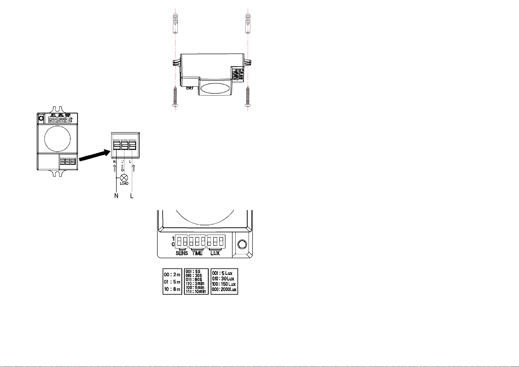
INSTALLATION: (see the diagram)
•Ensure all AC power is switched off.
•Fix the bottom on the selected position with the screw
through the screw holes in the side of the sensor.
•Connecting the power and the load to sensor as per the
connection-wire sketch diagram.
•Switch on the power to test.
CONNECTION-WIRE DIAGRAM:
TESTING THE SENSOR SWITCH:
•Slide the SENS knob: The first knob on “1”
position, the second knob on “0” position. Slide
the TIME knob: The first knob and second knob
on “0” position, the third knob on “1” position.
Slide the LUX knob: first knob on “0” position,
second and third knob on “0” position.
•When you switch on the power, the light will turn
on immediately. 5 seconds later the light should
turn off automatically. If motion is detected after
this the light should turn on. This indicates normal operation.
•If the motion sensor detects movement while the light is still on, it will reset the on-timer
delay from that moment.
•Slide LUX knob, first and second knob on “0” position,the third knob on “1” position. If the
ambient light is < 5LUX (darkness), the sensor switch will go into motion sensing mode.
Note: When testing in daylight, you must slide LUX knob to (000) 2000lux to allow the
sensor to work.
INSTALLATION NOTES
:
•This product must be installed & maintained only by a qualified, licensed electrician.
•Install the product in a secure location that does not sway or vibrate.
•Obstructive objects placed in front of the sensor may affect the sensing range.
•Avoid installation near metal or glass surfaces as this may affect reception range.
•For your safety, do not open case after installation (qualified electricians only).
•Install a 6A switch or circuit breaker in-line with the switched load to prevent sensor damage
due to overloading.
TROUBLESHOOTING:
•The connected load does not turn on:
a. Check the input power to the sensor. Ensure supplied voltage is between 220~240VAC.
b. Check to see if the indicator light is turned on after triggering – if it is, check the wiring to
the load.
c. If the indicator light does not turn on after triggering, try increasing the value of the LUX
daylight sensor settings.
•Poor motion detection sensitivity:
a. Ensure there are no objects between the sensor and the desired sensing location as
this could reduce the range.
b. Ensure that there are no other devices using the 5.8GHz band in close proximity to the
detector (eg: Wireless LAN, CCTV transmission equipment, etc.)
c. Ensure the installation height is (ceiling) 2~6m / (wall) 1.5~3.5m.
•The sensor does not turn off the load::
a. Check the TIME knob to ensure that the correct on-time delay has been selected
b. Ensure that there are no other devices using the 5.8Ghz band in close proximity to the
detector (e.g. Wireless LAN, CCTV transmission equipment, etc).
c. Ensure that the power drawn by the load is less than 1200W for a resistive load and
300W for an inductive load.

Popular Accessories manuals by other brands

Heitronic 36222 Installation and operating instructions

Heitronic

Heitronic 36222 Installation and operating instructions

NeuLog NUL-231 Guide

NeuLog

NeuLog NUL-231 Guide

BAMO IER MAXIMAT TC4 operating instructions

BAMO IER

BAMO IER MAXIMAT TC4 operating instructions

weinor BiConnect BiSens Agido-3V Operating and adjustment instructions

weinor

weinor BiConnect BiSens Agido-3V Operating and adjustment instructions

Conrad 55 44 04 operating instructions

Conrad

Conrad 55 44 04 operating instructions

Philips DLA66004D brochure

Philips

Philips DLA66004D brochure

Teledyne Detcon IR-700 instruction manual

Teledyne Detcon

Teledyne Detcon IR-700 instruction manual

Wenglor P1MH Series operating instructions

Wenglor

Wenglor P1MH Series operating instructions

Cardinal 220 Quick setup guide

Cardinal

Cardinal 220 Quick setup guide

PCB Piezotronics IMI SENSORS EX641B71D Installation and operating manual

PCB Piezotronics

PCB Piezotronics IMI SENSORS EX641B71D Installation and operating manual

Pepperl+Fuchs UC500-L2-E5-V15 manual

Pepperl+Fuchs

Pepperl+Fuchs UC500-L2-E5-V15 manual

Radica Games M7623 instruction manual

Radica Games

Radica Games M7623 instruction manual

tomado TM-1403 instruction manual

tomado

tomado TM-1403 instruction manual

Thermo Scientific Precision 818 Operating and maintenance manual

Thermo Scientific

Thermo Scientific Precision 818 Operating and maintenance manual

Nera WiLink-I Series System manual

Nera

Nera WiLink-I Series System manual

Emerson Micro Motion H Series installation manual

Emerson

Emerson Micro Motion H Series installation manual

CAME DNF10 manual

CAME

CAME DNF10 manual

Xoro MPB 500 Operation manual

Xoro

Xoro MPB 500 Operation manual

manuals.online logo
manuals.online logoBrands
  • About & Mission
  • Contact us
  • Privacy Policy
  • Terms and Conditions

Copyright 2025 Manuals.Online. All Rights Reserved.