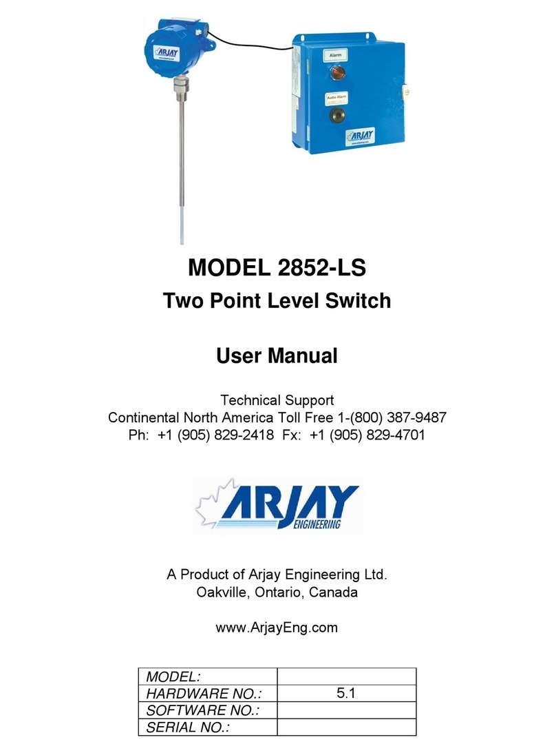
ENSIM SENSORS DX-ELF 101 User manual

OPERATING
MANUEL
ROTARY LEVEL SWITCH
DX-ELF
Model :
Model : 04-2022-008
Information in this manual is reviewed and completely reliable. Responsibility is not assumed due to any typing error.
Products in this manual are available only for information purpose and they may be changed without notice.
1
Models :
DX-ELF 101 , DX-ELF 102 , DX-ELF 103
DX-ELF 103p , DX-ELF 104 , DX-ELF 105
DX-ELF 106 , DX-ELF 106m , DX-ELF 108
DX-ELF 109 1783
Important Notes:
Used Symbols :
: Caution : Note : Disposal
Please read this manual carefully before installation of the rotary level switch. User is responsible for accidents and losses arising
from failure to comply with the warnings in this manual.
In the event that rotary level switch is broken, take measures in order to prevent accidents and losses which can occur in its system.
There is not any fuse and circuit breaker on the instrument; they should have been added to the system by the user.
This manual should be stored in an easily accessible place for subsequent use.
The manufacturer's liability cannot exceed the purchase price of the device according to the law.
Do not make any modification on the instrument and do not try to repair it. Reparation should be made by authorized service staff.
Do not operate the system before making assembly in compliance with the assembly chart related to the instrument.
Products which do not contain label and serial number are considered to be excluded from the warranty scope.
The instrument's useful life, determined and announced by the ministry, is 10 years.
Table of Contents :
General Information...........................................................................................................................................................................2
Installation .........................................................................................................................................................................................6
Failure Detection..............................................................................................................................................................................19
Disassembly of Instrument ............................................................................................................................................................19
Service .............................................................................................................................................................................................19
Recalibration....................................................................................................................................................................................19
Repair................................................................................................................................................................................................19
Disposal ...........................................................................................................................................................................................19
Terms of Warranty ..........................................................................................................................................................................19
Terms of Return ................................................19
1.
2.
3.
4.
5.
6.
7.
8.
9.
10.

2
For Dust ll 1/2D Ex ta/tb IIIC T*°C IP66
For Gas ll 1/2G Ex d IIC T*°C IP66
Loot at temperature class table
Certification
*
1. General Information :
1.1. Material Acceptance
Check that there is no damage on the packages during the transportation immediately after the material acceptance. If packages are
damaged, open the packages immediately and check whether products are affected or not, if there is any damage, send your
complaint report to the transporter company and its photocopy to the address of our company.
1.2. 1.2. Information about Areas of Use
Level Switch is designed for industrial facilities. It must not be used in mines. If its used in mines, resposibilty of manufacturer will be abolished.
Plastic Industry ; PVC, PVDF, PP granular etc..
Food Industry ; Grain Dust, Ground Corn, Sugar-Granulated,Cacao,
Malt-Graoung Dry, Sunflower Corn, Whead, Peanuts-Shelled,
Clays- Kaoline, Talcum Powder, Ground-Paprika, Coffee-Roasted vb..
Build Industry ; Rocks-Limestone Crushed, Lime, Cement Powder,
Rubber Ground, Lime Hydrate Dust, Calsium Dust, Iron Chips,
Silica Sand, Moulding Sand, Styrofaam etc..
Wood Industry ; Wooden Fiberst, Saw Dust etc..
Other Chemistry Industry ; Coal Lump, Ash-Coal Dry etc..
Ambient Conditions : Relative Humidity: 0-95 %RH Ambient Temperature: 60C (It is not used under -20 C)
Advantages
* Fast delivery period
* Reverse-rotation safety
* Adjustable precision
* Perfect mechanical durability
1.3. Working Princible
A palette selected according to the material is installed on the tip of the motorized level switch which can be installed on the tank wall. It revolves
idly with the revolution speed of the probe motor. Material to be detected reaches to the level of the palette and covers its circumference and
creates a counter-force according to the revolution force. Firstly, level information alarm contact is activated. Then, the other contact is
triggered and stops the motor. Adjustment of the spring in four different torque values according to specific weight of the material can be realized
by the user. When the material level at the end of the palette is decreased the created force is released and the motor starts to revolve, consequently,
changing the alarm position.
1.4. Technical Specifications and
Material Information
Certification and Approvals CE Declaration , EMC , LVD , ATEX
Working Temperature (Tp) (-) 20 .....(+) 90°C , (-) 20 .....(+) 60°C (With plastic connection type)
Opt. Max.150°C With High Temperature Type , Max.200°C With High Temperature Type
Working Pressure (-) 0,6 ... (+) 0,6 bar
LED Power LED: Green , Alarm LED: Red
Connection Aluminium , Opt. 304 / 316 Stainless Steel, PTFE, PVC, Delrin
304 Stainless Steel
Housing Aluminium Injection - AlSi12Fe (Std)
304 Stainless Steel ( Std) Opt. 316 Stainless Steel
Malzeme
Max. 4W
24 VDC +/- %10 , 24/48/110/220 VAC 50/60 Hz +/- %10
5 d/d (Std) (Clockwise - When Looking Paddle Side)
Opt. 1,5-1,8 d/d
1 BSP (Std) , Opt. 1 ¼ BSP , 1 1/2 BSP Male Thread
Cable and Stopper Input M20x1,5 (Std)
Relay Switching Capacity 10A/250 VAC - 4A/30VDC 2xNONC (SPDT) 5E4
Max. Grain Structure 50mm
Min. Density 0,04 g/cm3 (According to paddle type)
Torque Rating 4 Stages, adjustable
Protection Class IP 66 (EN60529)
Load on Probe Max. 500 N (Extention Pipe)
304 Stainless Steel ( Std) Opt. 316 Stainless Steel
Ambient Temperature (Ta) (-) 20 ... (+) 60°C
Ambient Humidity 0-98 %Rh (Non Condensate)
Black (RAL:9005)
NBR (Std) Opt. FPM (Viton) 150°C, PTFE 200°C
Elastomer Thermoplastic 120°C (Std) Opt. FPM (Viton) 150°C
Double ball bearing (With Dust-protected) (120°C) Opt. 280°C
Grounding Apparatus
Paddle And Rode
O-Ring for Cover
Bearing
Extension Pipe
Dust Protected Felting
Power Consumption
Revolutions Per Minute
Connection
Power Supply

LONCA A.Þ.
Ferhatpaþa Mah.Gazipaþa Cad. No:104A
34888 Ataþehir - ÝSTANBUL / TÜRKÝYE
Type B20x
www.ensim.com.tr
16A 240 VAC 50 / 60 Hz IE18030095-0014
S.No:
TSE 18ATEX0099
ll 1/2 G Ex d llC Tx*1 Ga/Gb
ll 1/2 D Ex (ta/tb)*3 lllC Tx*2
3
1.5. Label Information :
260 x 160 x 125 mm
Std.Kutu
1.7. Target Group
This operating manual has been prepared for qualified technical staff
1.8. Certifications and Approvals
:It shows that, product meets required conditions of EU with CE stamp
and stipulate that product passed quality assessment stages
TS EN 60079 - 0 : 2013
TS EN 60079 - 1 : 2014
TS EN 60079 - 31 : 2014
ATEX (2014 / 34 / AB) :
LVD (2014 / 35 / AB) : TS EN 61010 - 1 : 2012
TS 3033 EN 60529 : 1397
TS EN 61326 - 1 : 2013EMC (2014 / 108 / AT) :
1.6. Package and package contents :
Please check whether you have taken delivery of below listed
content completely or not and check its conformity with criterions
in your order:
*Rotary Level switch
*This operating manual
LONCA A.Þ. , who is the manufacturer company, applied all features and test, that stated in this document, to the all products,
that produced as DX-ELF model.
Note :
Box
Label
Type
Rotary Level Switch
S.N.
Quantity
DX-ELF 101-1-006-31-1-1-81-1-02-00/0
160999-004
:
:
1 pc.:
Serial Number
Type
Quantity
Patlayýcý
Ortam Korumasý
Ürün Ýsmi
Barcode
Manual must be read before installation
Supply 24VDC %10:
IE18030011-0014
Power Supply
Insulation
Label
Approved
institution Sign
Caution Symbols
Web Adress
In conditions that product label become damaged in ATEX certificated
products, application is possible to the manufacturer with serial number
on metal label within products body
Type Serial
Number
Properties
Explosive Environment
Protection
Note :
ATEX Classes
Metal
Label
Type
Serial
Number
Explosive Environment
Protection
Product
Name
Working
Condition
Manufacturer
Name
Product
Label
Type
Power Supply
Contact Output
Process Temp. / Press.
T (Ambient)
Serial Number
Rotary Level Switch
:
:
:
:
:
:
DX-ELF 101-1-006-31-1-1-81-1-02-00/0
24VDC +/- %10
2A/250 VAC 2xNO-NC (SPDT)
-20...+90°C / -0,6 ... +0,6 bar
-20...+60°C
IE18030011-0014
www.ensim.com.tr
MADE IN TURKIYE
1783
IE 18 03 0095 - 0014
Product Number
System Number
Month
Year
Production Order
Manufacturer
Adress
Web Adress
Manufacturer
Name

4
1.9. Safety Instructions ( ATEX )
All safety instructions must be read and fullfilled.
- All notes below must be paid attention to avoid dangers that might occur near operator and his environment.
- Installation of this device , usage and service must be done by people who read manual and have knowledge about work safety.
-Products must be controlled, if its mounted properly according to zone map of products by user
-Work safety, accident prevention regulations and universal installation standards must be complied.
- Product must be used only within stated specifications.
- Device can be mounted only when there is no pressure.
-This safety instructions are only for products that coded as DX-ELF and protected from in terms of explosion threat, categorized in 1/2 D and 1/2 G.
It is compatible with TSE 18ATEX0099 and CE certificate
- It must be used compatible in order to properties on label.
-Because of environment temperature can be maximum 80*C , cable must be choosen compatible.
- In order to not affect IP protection class , do not tighten cable socket excessively ( Max: 5Nm)
- Ensure that cable input and plug tighten correctly
- Ground connection must be done correctly and controlled before energized.
- Before energized and using the product, cover and setskur screw must be controlled that tighten enough
- DX-ELF models have metal casings and those are compatible with engines that have different supply and voltage shown in catalogue
- Metal casing must be inside 2D or 2G zone. Rode and paddle part must be inside 1D or 1G zone
- Maximum working temperature and maximum surface temperature are variable in order to product model.
Documents must be read carefully before usage.
- Mechanical tension and deformations on tanks surface must be checked in assembly process.
When, a situation occurs like that, sensor must not be energized before taking necessary precautions
- The pressure inside the tank must be controlled that not above from working pressure stated in catalogue
- Assembly of sensor must be compatible with tank loading system. In conditions that are not compatible , inside the tank must be protected with
protection apparatuses
- The sensor has designed as to withstand materials chemical affects that in proper environmental conditions which is stated in this manual.
Other materials compatibility must be controlled.
- Flange surface smoothness must be maintained in flanged connection.
- Flange seating surface should not be scratched, and suitable liquid gasket should be used instead of sealing with gasket in counter flange mounting.
- Flanged connections are welded with the sensor part.
- Sensor must be protected against moisture and dust in proper storage conditions.
- Repairs of device must be done only in LONCA A.Þ which is manufacturer company.
- Device must be protected against friction and cleaning must be done without water.
- In an inappropriate circuit condition, before replacing the temperature circuit breaker with its backup , main power must be turned off completely
and safety precautions must be taken. Changing must be done in a safe area.

5
1.10. ATEX Symbols Explanations
II 1/2 D Ex ta/tb IIIC T4 IP66
II 1/2 G Ex d IIC T4 IP66
Dust
Gas
Explosive
Environment
Proctection
Equipment
Group
Equipment
Category
Proctection
Type
Dust Type
Temperature Class (Max.Surface Temperature)
Housing Protection
Class
Explosive
Atmosphere
Type
Explosive
Proctection
Explosive
Environment
Proctection
Equipment
Group
Equipment
Category
Proctection
Type
Gas Type
Temperature Class (Max.Surface Temperature)
Housing Protection
Class
Explosive
Atmosphere
Type
Explosive
Proctection

6
Mounting
Shape
Double-Bladed Collapsible
Paddle Mounting
For scimitar paddle mounting
2. Installation :
2.1. General Notes
Installation of device must be done by only authorized staff, that has known about 2014/34/EU criterias,
for ensuring safety against explosion and liable against preventing harms to third party
Installation of the instrument should be made only by authorized staff.
Do not apply force to the instrument during the installation!
Do not use the level switch with a greater pressure than recommended pressure.
Do not forget that instrument is precise, carry it carefully and prevent to be damaged.
It should be guaranteed that there are not any magnetic particles.
Max. Working Pressure must not be exceeded.
2.2. General Installation Stages
*Remove level switch from the box carefully
*Check whether gasket is appropriate for fluid or not. If is not appropriate, contact with the manufacturer.
*Then, apply below mentioned explanations according to structure of the design.
2.3. Special Notes
*Please ensure that there is no mechanical stress on the shaft following installation.
Such case will cause slipping in the characteristic curve.
*Level switch should be placed in completely vertical or horizantal position to the tank.
*Allocate valve certainly in the process connection while instrument is used.
*Allocate blowdown valve under bottom flange for blowdown.
*If instrument is mounted outside and if there is any danger of lightning or excessive pressure,please take precawtions to prevent any harm.
*In the operating conditions, level switch may be hot according to situation of fluid, in this case, do not touch the switch, otherwise your
skin can be harmed.
*Insulation of product must be done properly (It can be done externally or inside the housing.)
2.4. Installation For Mechanical Connections
*Use appropriate O-Ring or gasket for tightness.
*Ensure that its surface is clean and smooth.
*Assemble the instrument manually.
*Connect the contacts as shown in the figure. (Max.20 Nm for G1", Max.30 Nm for G1 1/4" and G1 1/2" )
It closes on
clockwise turn

7
2.5. Torque calibration mechanism :
Torque spring should be used for recalibration of shaft's output torque which is set as low and weak in factory settings.
Calibration of torque spring can be adjust to material's weight and density which is specified by customer.
If the density of measured material is high, please set the spring to strong position until to get optimal working conditions.
High torque setting must be choosen in materials that has adhesion tendency and moist properties.
Low torque setting must be choosen for materials that has low density and dry properties
2.5. Example Mounting Types:
Normaly Working
During an Alarm
Supply Motor Position Output Position Alarm LED Position
Yes
Yes
Yes
Yes
Stop
Stop
Stop
-
-
Full
Full
Full
On light
On light
On light
Uninspiring
Working Position
h
Factory Area
(Safe)
ZONE 21 / 1
or
ZONE 22 / 2
Process Side
ZONE 20 / 0
or
ZONE 21 / 1
or
ZONE 22 / 2
Process Side
ZONE 20 / 0
or
ZONE 21 / 1
or
ZONE 22 / 2
Full
Empty
Protection
Barier-Tank
Input
Extention
Shaft
Mini Shaft
Long
Shaft
Std. Shaft
Std. Shaft
h: The Mounted according
by paddle
Should not be connected
to the corner
Extention Shaft
Without Protection
Pipe
Should not
connect to exit
In tank
No Protection
Barier
Input
Should not be connected
to the entrance
2.6. Switching Logic :
NO
NC C
+
+
NO
NC C
NO
NC C
+
+
NO
NC C
Contact
Terminal
Contact
Terminal
Contact
Terminal
Contact
Terminal
On Off
Empty Tank Full Tank
Off
On

MODULAR STRUCTURE:
8
2.8. Mecahanical Parts and Connection Apparatus:
2.7. Electrical Installation
Make the electrical connection of the instrument according to details on its label, table and cable figures in this manual.
L
(+) N
(-)
Signal Power
NO
NC C
L+
N-
1234
AC
DC
Min.
Low
Medium
High
220 VAC
110 VAC
24 VAC
24 VDC
Note : It has been produced according to IPC A 600 class 2 conditions and tested with 100 % E-test. Moreover,
HASL (non-lead) surface test has been applied.
24 VDC
Power Supply
Table
Alarm
Switch Engine
Apparatus Engine
Switch Electronic
Card
Power
LED
Contact
LED
External
LED Spring
Supply
Terminal
Recommended Cable (5x1,5 mm2)
Protective Conductor (Max.1,5 mm2)
Contact
Terminal
ELF-Dx
SIGNAL
PWR
Thermal Fuse
PWR
SIGNAL
ELF-Dx
Insulation Terminal
(Max.1,5 mm2)
Recommended Cable (5x1,5 mm2)
Bund Stops
Aluminium Housing
Factory Section
(Safe)
ZONE 21 / 1
or
ZONE 22 / 2
Process Side
(Explosive
environment)
ZONE 20 / 0
or
ZONE 21 / 1
or
ZONE 22 / 2
Metal Label
Ta Tp
Cover Chain Screw
Cable Plug
(Suitable Cable Diameter : Ø 6-12mm)
DO NOT OPEN WHEN ENERGIZED
KEEP TIGHT WHEN CIRCUIT ALIVE
M3
Cover Body Label Thread Rode PaddleO-Ring Fixing pin
Paddle Mechanics
Body Mechanics
Engine Mechanics
Metal Label
Product Label

9
2.9. Connection Accessories :
You can consult our company for the Ex-proof models.
Flange :
Note : 1BSP With 1 Nut-Aluminium
33,5
k
D1
D
d
33,5
Order
Code
/ F1
/ F2
/ F3
/ F4
D1 Material
110
110
200
200
304 St.St.
Dkd Number of
Hole
316 St.St.
304 St.St.
316 St.St.
4
4
6
6
2
2
2
2
8
8
8
8
90
90
180
180
Muff :
D
L
R
Order
Code
R
/ M1
/ M2
/ M3
/ M4
L
mm
Material
304 St.St.
D
mm
/ M5
/ M6
/ M7
/ M8
/ M9
1BSP
1 1/4BSP
1 1/2BSP
1BSP
1 1/4BSP
2BSP
1BSP
1 1/4BSP
1 1/2BSP
304 St.St.
304 St.St.
316 St.St.
316 St.St.
316 St.St.
ST 37 Steel
ST 37 Steel
ST 37 Steel
Ø 37
Ø 47,5
Ø 54,4
Ø 37,6
Ø 47,8
Ø 52,6
41
40,2
46,5
47
48,1
46,5
41
46,5
48,1
Ø 37
Ø 47,5
Ø 54,4
Reduction :
R
L
Hex r
Order
Code
R
/ R1
/ R2
/ R3
/ R4
r L
mm
Material
1BSP
1BSP
1BSP
1BSP
1 1/4 BSP
1 1/2 BSP
1 1/4 BSP
1 1/2 BSP
304 St.St.
21
19
19
304 St.St.
316 St.St.
316 St.St.
21
/ R5
/ R6
1BSP
1BSP
1 1/4 BSP
1 1/2 BSP 22,5
ST 37 Steel
ST 37 Steel
22
Hex
44
50
50
44
50
45
/ R7 1BSP 2 BSP 25 304 St.St.60
Protection Case:
Material : 304 St. St.
Welded Production
Open - Close hinged
For Protection of switch from external conditions

10
** Tolerance -/+ 5 mm .
2.10. Sample Models :
102 mm
DX-ELF 101
51Hex 1BSP
90°C Opt. 150°C
Vertical / Horizontal Mounting
Weight
2,1 kg
Ø9
129 mm
150 mm**157 mm
102 mm
DX-ELF 102
51Hex 1BSP Ø9
Max. 2 m**
102 mm
157 mm
DX-ELF 103
90°C Opt. 150°C
Vertical Mounting
Weight
2,2 kg
69 mm
51Hex 1BSP
Ø9
115 mm**
157 mm
Direction of rotation
150 mm**157 mm
102 mm
51Hex 1BSP Ø9
92 mm
90°C Opt. 150°C
Vertical / Horizontal Mounting
Weight
2,1 kg
DX-ELF 104
102 mm
51Hex 1BSP
(St.St.) Ø27 Ø9
Max. 2 m**
157 mm
Std.250 mm
90°C Opt. 150°C
Vertical / Horizontal Mounting
Weight
2,6 kg
Ø9
540 mm**
250 mm**157 mm
102 mm
51Hex 1BSP
DX-
ELF 103p
(For EPS-XPS)
Direction of rotation
Direction of rotation
129 mm
Direction of rotation
Direction of rotation
129 mm
Direction of rotation
DX-ELF 105
(-20)...+60°C
Vertical / Horizontal Mounting
Weight
2,2 kg
90°C Opt. 150°C
Vertical / Horizontal Mounting
Weight
2,1 kg

11
Sample Models :
** Tolerance -/+ 5 mm .
DX-ELF 106
132 mmMax. 2mt*
102 mm
Std 250mm
Ø34
Ø34
Ø9
129 mm
Direction of rotation
Opt.200°C
Vertical / Horizontal Mounting
Weight
2,8 kg
100 mm.
150°C
Vertical / Horizontal Mounting
Weight
2,4 kg
132 mm100 mm.Max. 500mm.**
102 mm
Ø34
51Hex
Ø9
129 mm
Direction of rotation
1BSP
(St.St.)
DX-ELF 106m
Opt.200°C
Vertical / Horizontal Mounting
Weight
2,4 kg
132 mmMax. 2m**
102 mm
Std 250mm
Ø34
Ø27
Ø9
129 mm
Direction of rotation
150°C
Vertical / Horizontal Mounting
Weight
2,8 kg
100 mm.
51Hex 51Hex
1 14 BSP
(St.St.) 1 14 BSP
(St.St.)
132 mm100 mm.Max. 500mm.**
102 mm
Ø34
51Hex
Ø9
129 mm
Direction of rotation
1 14 BSP
(St.St.)

12
Sample Models :
** Tolerance -/+ 5 mm .
DX-ELF 108 DX-ELF 109
102 mm
265 mm
Max. 2 m** 157 mm
Ø4 Rope
1BSP
Max. 10 m**
Ø8 Rope
102 mm
157 mm
51Hex
Direction of rotation
90°C Opt. 150°C
Vertical Mounting
Weight
2,7 kg
Direction of rotation
90°C Opt. 150°C
Vertical Mounting
Weight
3,4 kg
265 mm
51Hex
1BSP

13
2.12. Maximum surface temperature
STD.
MODEL
DX-ELF 108
DX-ELF 109
DX-ELF 106
DX-ELF 106m
DX-ELF 104
DX-ELF 105
DX-ELF 103pDX-ELF 101
DX-ELF 102
DX-ELF 103
Stand by time before
opening the cover dk. dk.
dk.
Working Temperature (-)20...(+)90°C (-)20...(+)60°C (-)20...(+)150°C
Working temperature
in plastic types
Thermal Protection Insurance.............105°C
(-)20...(+)60°C
30° C
40° C
50° C
60° C
200° C
200° C
200° C
200° C
DX-ELF 106 - DX-ELF 106m
30° C
40° C
50° C
60° C
150° C
150° C
150° C
150° C
65° C
70° C
82° C
91° C
T6
T6
T6
T5
DX-ELF 101 - DX-ELF 102 - DX-ELF 103 - DX-ELF 104 - DX- ELF 105 - DX-ELF 106 - DX-ELF 106m - DX-ELF 108 - DX-ELF 109
30° C
40° C
50° C
60° C
60° C
60° C
60° C
60° C
° C
° C
° C
° C
DX-ELF 103p
T Environment
MAX. AMBIENT TEMPERATURE
ZONE 21 / 1
30° C
T Process
MAX. PROCESS TEMPERATURE
ZONE 20 / 0
T Surface
MAX. SURFACE TEMPERATURE
TEMPERATURE CLASS
40° C
50° C
60° C
90° C
90° C
90° C
90° C
58° C
65° C
78° C
88° C
T6
T6
T6
T5
DX-ELF 101 - DX-ELF 102 - DX-ELF 103 - DX-ELF 104 - DX- ELF 105 - DX-ELF 108 - DX-ELF 109
(-) 20° C < T environment < (+) 30° C...(+) 60° C Working temperature :(-) 20...(+) 90°C
(-) 20° C < T environment < (+) 30° C...(+) 60° C Working temperature :(-) 20...(+) 60°C
T Environment
MAX. AMBIENT TEMPERATURE
ZONE 21 / 1
T Process
MAX. PROCESS TEMPERATURE
ZONE 20 / 0
T Surface
MAX. SURFACE TEMPERATURE
TEMPERATURE CLASS
(-) 20° C < T environment < (+) 30° C...(+) 60° C Working temperature :(-) 20...(+) 150°C
T Environment
MAX. AMBIENT TEMPERATURE
ZONE 21 / 1
T Process
MAX. PROCESS TEMPERATURE
ZONE 20 / 0
T Surface
MAX. SURFACE TEMPERATURE
TEMPERATURE CLASS
T Environment
MAX. AMBIENT TEMPERATURE
ZONE 21 / 1
T Process
MAX. PROCESS TEMPERATURE
ZONE 20 / 0
T Surface
MAX. SURFACE TEMPERATURE
TEMPERATURE CLASS
(-) 20° C < T environment < (+) 30° C...(+) 60° C Working temperature :(-) 20...(+) 200°C
50° C
54° C
64° C
80° C
T6
T6
T6
T6
Important Note : Wall thickness of the product is manufactured as 3 mm from stainless stell for he temperature class tests.
Where the isolation is thinner , autorized technical personnel must take precautions.

14
2.12. Paddle Shapes :
Standard
Scimitar Paddle
(258mm)
Mini
Scimitar Paddle
(138mm)
Double-Baded
Collapsible Paddle
(265mm)
Double-Baded
Collapsible Paddle
(540mm)
550
1350-1510
50-160
400-800
195
550-710
730-990
330
480-560
1370-1510
1510
540-575
350-480
Chopped Corn
Crushed limestone
Sawdust
Rubber Floor
Tea Leaves
Shelled Peanut
Dusting Powder
Acrylic Resin
Wheat flour
Cement Dust
Silica Sand
Lumpy Polypropylene
Roasted Coffee
Metals, Iron Chips
Coal Pellet
Dry Malt Floor
Dry Coarse Coal
Grain - Oat
Sugary Granule
Wheat
Breadstuff
Aquaous Lime Powder
Powder PVC
Granule PVC
Sunflower Marsh
Red Pepper
2650
400-800
310
560-725
400-560
880
400-500
600-800
400-500
300-600
300-600
300-500
800-1000
Material Min.Density
(Kg/m3) Material Min.Density
(Kg/m3)
Weigh
75 gr.
Weigh
235 gr.
Weigh
120 gr.
(Plexiglass)
Paddle 11
Weigh
185 gr.
Weigh
515 gr.
Weigh
105 gr.
Paddle 09
Paddle 10
(304 St.St.)
(316 St.St.)
Paddle 07
Paddle 08
(304 St.St.)
(316 St.St.)
Paddle 12
Paddle 13
(304 St.St.)
(316 St.St.)
Paddle 14
Paddle 15
(304 St.St.)
(316 St.St.)
Paddle 01
Paddle 02
(304 St.St.)
(316 St.St.)
Paddle 03
Paddle 04
(304 St.St.)
(316 St.St.)
Paddle 05
Paddle 06
(304 St.St.)
(316 St.St.)
Cross-Wing
Paddle
(105x90mm)
Cross-Wing
Paddle
(148x98mm)
Single Wing
Paddle
(75x35mm)
Single Wing
Paddle
(80x65mm)
Density of examples that can be applicable :

Chain
Cover
Cover Seal
Printed-Circuit Card
Insulation Screw
Insulation Internal Bracket
Insulation External Bracket
Plug
Insulation Screw
Cable Thread
Metal Label
BodySetscrew
Body Seal
Marble
Segment
Body
Setscrew
Product Label
Body
Engine
Cover Setscrew
Insulation Label
Spring
Apparatus
Spring
Paddle
Segment
Rode
Bearing
Bearing
Connection Threah
Felting
Pin
15
2.13. Parts Names :

2.14 . Order Form
Order Form : Please consider sample models when coding
16
PADDLE TYPE
CONNECTION
1" BSP Male Thread (Std)...........................0006
1 1/4" BSP Male Thread ............................0008
1 1/2" BSP Male Thread .....................................0010
Special.......................................................................x
REVOLUTIONS PER MINUTE
5 rpm (Std) .........................................................1
1,5 rpm ...................................................2
8
Special.......................................................................x
4
CONNECTION MATERIAL
6
POWER SUPPLY
7
5
Standart Shaft - L= 150 mm.............................1
Mini Shaft - L= 75 mm......................................2
Long Shaft - L= 500 mm ..................................3
Standart Shaft - L= 250 mm...........................3p
Single Shaft - L= 500 mm ................................4
Cable Extented Shaft - L= 500 mm.................5
SHAFT TYPE - (STEM LENGHT)
Shaft With Extention Tube - L= 2m.(For High Temperature)...........6
Mini-Shaft With Extention Tube - L= 150mm Max.500........6m
Rope Shaft - L= 2000 mm)..............................................................8
Reinforced Rope (28 KN) - L= Max.10 m................................9
Special........................................................................................x
3
Standart.............................................................1
MODEL DX-ELF
1
None.................................................................0
CERTIFICATE
2
(EN10204-3-1) Material Certification............................1
304 Stainless Steel......................................0001
316 Stainless Steel......................................0002
Aluminium (Std).............................................031
Special.......................................................................x
24 VDC..............................................................1
24 VAC 50/60 Hz ± %10 ..................................2
110 VAC 50/60 Hz ± %10.................................3
220 VAC 50/60 Hz ± %10..........................................4
48 VAC 50/60 Hz ± %10............................................5
Special.......................................................................x
*
*
Those can be choosen(applicable)only products
with 90 Celcius working temprature.
Without Paddle (184 mm) .......................................................00
Standart Scimater Paddle (258 mm)..................304 St. St. ....01
Standart Scimater Paddle (258 mm)..................316 St. St. ....02
Mini Paddle (138 mm)........................................304 St. St. ....03
Mini Paddle (138 mm)........................................316 St. St. ....04
Double-Baded Collapsible Paddle (265 mm).....304 St. St. ....05
Double-Baded Collapsible Paddle (265 mm).....316 St. St. ....06
Cross-Wing Paddle (148x98 mm)................304 St. St. ....07
Cross-Wing Paddle (148x98 mm)................316 St. St. ....08
Cross-Wing Paddle (105x90 mm)................304 St. St. ....09
Cross-Wing Paddle (105x90 mm)................316 St. St. ....10
Double-Baded Collapsible Paddle-Plexiglass (540 mm)....11
Single Wing Paddle (75x35 mm)..................304 St. St. ....12
Single Wing Paddle (75x35 mm)..................316 St. St. ....13
Single Wing Paddle (80x65 mm)..................304 St. St. ....14
Single Wing Paddle (80x65 mm)..................316 St. St. ....15
Special..................................................................................x

17
DX-ELF 101 - 001 - 0006 - 031 - 1 - 1 - 0081 - 1 - 703 - 00 / 0
Rotary Level Switch , DX-ELF 101 , Standard Paddle , L=150 mm , 1 BSP, 24VDC
SAMPLE
ROLLER
10
MATERIAL OF POWDER FEELTING
9
Special........................................................................x
OPTIONAL
None................................................................................./ 0
Reduction 1 BSP - 1 1/4" BSP 304 St.St....................../ R1
Reduction 1 BSP - 1 1/2" BSP 304 St.St....................../ R2
Reduction 1 BSP - 1 1/4" BSP 316 St.St....................../ R3
Reduction 1 BSP - 1 1/2" BSP 316 St.St....................../ R4
Reduction 1 BSP - 1 1/4" BSP ST 37 Steel................../ R5
Reduction 1 BSP - 1 1/2" BSP ST 37 Steel................../ R6
Reduction 1 BSP - 2" BSP 304 St.St............................/ R7
Flange with muff 110 mm 304 St.St.............................../ F1
Flange with muff 110 mm 316 St.St.............................../ F2
Flange with muff 200 mm 304 St.St.............................../ F3
Flange with muff 200 mm 316 St.St.............................../ F4
Protection plate 304 St.St............................................../ K1
Shelter - (For the outside of the tank) 304 St.St. ........../ K2
13
Muff 1 BSP 304 St.St........................................../ M1
Muff 1 1/4 BSP 304 St.St..................................../ M2
Muff 1 1/2 BSP 304 St.St.................................../ M3
Muff 1 BSP 316 St.St......................................../ M4
Muff 1 1/4 BSP 316 St.St................................../ M5
Muff 1 1/2 BSP 316 St.St..................................../ M6
Muff 1 St 37 Steel............................................./ M7
Muff 1 1/4 ST 37 Steel......................................../ M8
Muff 1 1/2 ST 37 Steel....................................../ M9
M12 x 5 pin socket (Max. 60 V)............................/ S1
External LED socket............................................./ L1
Change for body - Cover ...................................../ Z1
Special.....................................................................x
HOUSING MATERIALS
Special........................................................................x
11
Aluminum B21x , IP66........................704
ELECTRICAL CONNECTION
Special........................................................................x
12
With Terminal........................................00
Important Note : In hight temprature aplications , felting and protection material
must be selected appropriately.
Metal Ball Bearing 280 °C.........................................3
Metal Ball Bearing 200 °C.........................................4
Metal Ball Bearing 330 °C.........................................5
Special.......................................................................x
Metal Ball Bearing (Std) 120 °C............1
Ceramic Ball Bearing..............................2
PTFE Max. 200 °C............................0066
NBR (Std) Max.90 °C.......................0081
FPM Maxs. 150 °C............................0085

18
2.15. WARNINGS !!!
Please pay attention to following matters in order to operate your level switch properly.
Do not pull the cable strongly,
otherwise the characteristics
might be changed.
Please keep away from magnetic materials
like iron board ; otherwise the
characteristics might be affected.
Please do not drop ,
otherwise the characteristics
might be changed..
Please do not dip cables
potting into liquids,otherwise
instulation problem may cause..
Please keep away from magnetic
field ,otherwise it might
be mis-operated.
Vibration might be
caused instability.
Do not remove the plastic parts
of the bottom of the switch body,
do not loosen.
In case vapour splash cable
potting points,insulation
problem may cause.
Excess current , to be drawn as
a result of direct connection to motor,
may burn relay of switch
Due not use with materials which
may damage the material.
No material shall not drop on the pedal.
Cover the top with guard plate.
Do not connect the switch
with inverted polarity.
It characteristics may change.
iron board

19
Failure
3. Failure Delection
Possible cause Troubleshooting/remedy
If you find an error, try to eliminate it by using this table or send the instrument to our service address for repair.
The instrument should be repaired only by authorized service! Serial number shall be indicated to the authorized service center.
4. Disassembly of Instrument
Instrument should be disassembled while feeding and pressure is not available!
5. Service
6. Re-Calibration
During long period usage of level switch, there might be deviations on measurements. In those cases, recalibration is recomended. Re-calibration could be made by your
technical staff or you could send to manufacturer company. According to IEC 60017, ex proof devices must be go through detailed inspection every 3 year from purchase
date.Respobsibility of inspections are belong to the user ( IEC: International Electrotechnical Commission)
7. Repair Manufacturer Address
If irreparable breakdowns occur, the instrument should be sent to us for repair purpose. Before this, the instrument should be cleaned carefully and packaged
so as not to be broken. Furthermore, you should also add a detailed explanation which describes the breakdown while instrument is sent. If your instrument
contacts with harmful substances, decontamination report should be also sent additionally. In the event that instrument does not have any decontamination
report or our service department has doubts about instrument, repair process will not start until an acceptable report is sent.
8. Disposal
The instrument should be disposed according to 2002/96/EC and 2003/108/EC European Directives (waste electrical and electronic instruments).
Waste electrical and electronic equipment should not be mixed with domestic wastes!
If the instrument has contacted with harmful substances, special attention should be paid for its disposal!
9. Terms of Warranty
The instrument has warranty legally for 24 months after delivery date. Warranty demands are not accepted in case of inappropriate operation, damage on the
instrument or any modification on the instrument.
10. Terms of Return
In the return of materials, user should send an open list related to damage or problem, malfunction of the material to be returned or its operation in the different
modification, with the instrument. If it is required to return the material, used in the dangerous, corrosive or toxic fluid, in this case, used part should be cleaned
very carefully. Security of staff should be ensured. All products to be returned should be sent to our company address, which
we have stated.
The instrument does not require maintenance. If it is desired, residue accumulated inside should be blown according to kind of fluid and instrument can be cleaned
with soft cleaning solutions. Measures should be taken during the disassembly.
If the instrument contacts with hazardous substances, necessary measures should be taken for decontamination!
Service -Manufacturer Company Name and Address:
LONCA MAK. SAN. TÝC. A.Þ. Ferhatpaþa Mah. Gazipaþa Cad. No: 104A Ataþehir - ÝSTANBUL - TÜRKÝYE
Housing is broken Product fell down or suffered external impact Notify the authorized service center.
Noises come from
the product.
-Bearing may be broken.
-Bearing lubrication function may be degraded.
-Spring may be broken.
-Seal may be broken
-Board screws may be loose.
-Notify the authorized service center.
-Check and retighten the screws.
Signals no contact or
always signals contact
-The contact may be burnt-out.
-Installation angle may be wrong.
-Socket may be damaged.
-Product may be exposed to magnetic field
in the environment.
-Values higher than operating current
and/or voltage are used.
-Water has infiltrated in the housing.
-Notify the authorized service center.
-Correct the installation angle.
-Check the socket connections.
-Ensure that the electrical connection points
downward.
-Check the gaskets.
Unstable operation
of the contact
-Product fell down or suffered external impact
-Correct spring position is not selected.
-Correct palette is not selected.
-Notify the authorized service center.
-Contact the manufacturer for palette suitable
for the material.
Motor running but no
signal is being received.
-The pedal may be dislocated.
-The material may not have reached to switch level.
-Palette is not selection is not made according
to the density of the material.
-Check and reinstall the pedal.
-Check if the switch is installed to the right
position.
This manual suits for next models
9
Table of contents
Other ENSIM SENSORS Switch manuals
ENSIM SENSORS
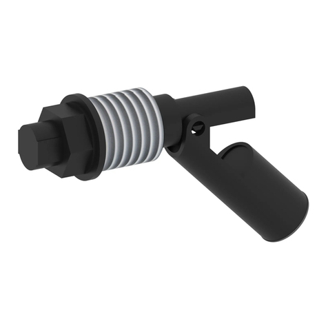
ENSIM SENSORS ELP User manual
ENSIM SENSORS
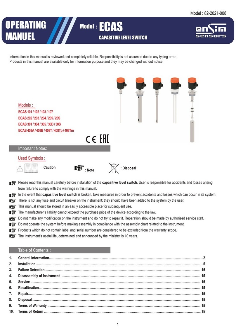
ENSIM SENSORS ECAS 101 User manual
ENSIM SENSORS
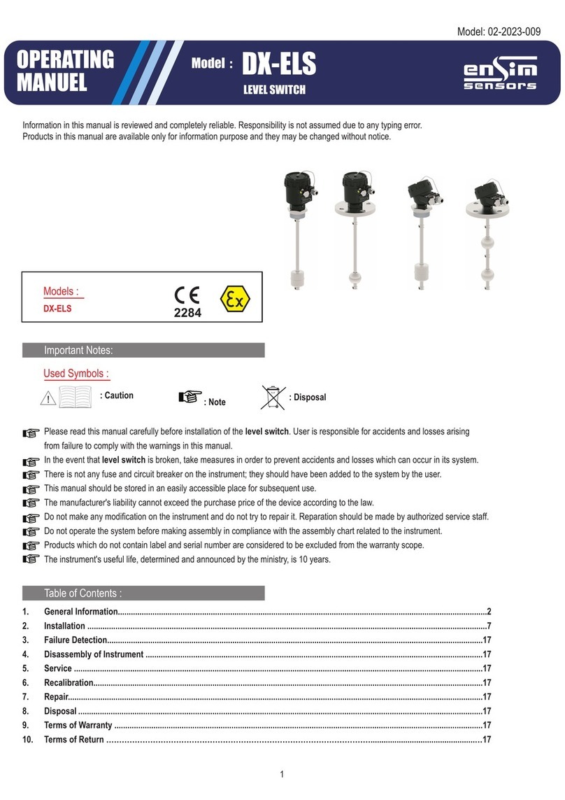
ENSIM SENSORS DX-ELS User manual
ENSIM SENSORS
ENSIM SENSORS ELP Series User manual
ENSIM SENSORS
ENSIM SENSORS EFS User manual
ENSIM SENSORS
ENSIM SENSORS ELC 21d User manual
ENSIM SENSORS
ENSIM SENSORS DX-ELS Series User manual
ENSIM SENSORS
ENSIM SENSORS DX-ELB 11 User manual
ENSIM SENSORS
ENSIM SENSORS ELM Series User manual
ENSIM SENSORS
ENSIM SENSORS ELS User manual
