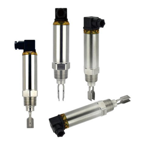
ENSIM SENSORS ELT User manual

OPERATING
MANUEL
VIBRATING TYPE LEVEL SWITCH
ELT
Model :
Model : 51-2021-003
Important Notes:
Used Symbols :
Please read this manual carefully before installation of the level switch. User is responsible for
accidents and losses arising from failure to comply with the warnings in this manual.
In the event that level switch is broken, take measures in order to prevent accidents and losses which
can occur in its system.
There is not any fuse and circuit breaker on the instrument; they should have been added to the system
by the user.
This manual should be stored in an easily accessible place for subsequent use.
Do not operate the system before making assembly in compliance with the assembly chart related
to the instrument.
Do not make any modification on the instrument and do not try to repair it. Reparation should be made
by authorized service personnel.
The instrument's useful life, determined and announced by the ministry, is 10 years.
Products which do not contain label and serial number are considered to be excluded from the warranty scope.
: Caution : Note
Table of Contents :
1. General Information...........................................................................................................................................2
2. Installation ..................................................................................................................................................3
3. Failure Detection..............................................................................................................................................6
4. Disassembly of Instrument ..................................................................................................................................6
5. Service ......................................................................................................................................................6
6. Recalibration...............................................................................................................................6
7. Repair....................................................................................................................................................................6
8. Disposal................................................................................................................................................6
9. Terms of Warranty .....................................................................................................................................6
10.Terms of Return ..............6
1
: Disposal
Modeller :
Information in this manual is reviewed and completely reliable. Responsibility is not assumed due to any typing error.
Products in this manual are available only for information purpose and they may be changed without notice.
ELT 101 , ELT 102 , ELT 103 , ELT 104
ELT 201 , ELT 202 , ELT 204

2
1. General Information :
1.1. Material Acceptance
Check that there is no damage on the packages during the transportation immediately after the material acceptance. If packages are
damaged, open the packages immediately and check whether products are affected or not, if there is any damage, send your
complaint report to the transporter company and its photocopy to the address of our company.
1.2. Information about Areas of Use
ELT series single vibrating material level switch is one of the tuning fork material level switches. It is not afraid of hanging materials, not afraid
of impact, without clamping problems, and has higher sensitivity.Its cylindrical single measuring rod structure determines its wider
adaptability to industrial field.
Areas of Application :
Sugar, Hazelnut, Clay, Sunflower Seed, Coffee, Various Granules, Wheat, Bauxite, Ceramic, Legumes, Cereal, Fish Feed, Sand, Pebble,
Isolation Materials, Corn, Rice ...
Ambient Conditions: Relative Humidity: 5-95 %RH Ambient temperature: 60 °C (It is not used under -5 C)
1.3. Working Principle
Single rod vibrating level switch uses the "resonance" principle of tuning fork to generate vibration
under the driving of piezoelectric elements.
Only when all around the probe rod are surrounded by materials, the vibration amplitude will be
sharply reduced, resulting in switch action.
1.4. Technical Specifications :
(((
(((
Fluid
Wet Parts
Fork Material
Housing Material
Max. Solid Particle Size
Max. Liquid Viscosity
Measurement Density
Vibration Frequency
Delay
Time
Exit
Supply
Power consumption
Connection
Working Pressure
Working Temperature
Ambient Temperature
Ambient Humidity
Protection Class (EN60529)
(For ELT101, 201)
(For ELT103)
(For ELT102,104, 202, 204)
Liquid, Solid, Powder
316 Stainless Steel
316 Stainless Steel
Aluminuim, Stainless Steel (For ELT103)
<10 mm
<1000 mm² / sec
For Solid> 0,1 g / cm³
For Liquid> 0.7 g / cm³
280 KHz (For ELT102,104, 202, 204)
300 ± 50KHz (For ELT101, 201)
0.5 sec (Vibration Stop)
1-2 sec (Vibration Start)
It can be adjusted between 1-60 seconds.
1 x 3A NO / NC Relay 30 VDC / 220 VAC
1 x 5A NO / NC Relay 30 VDC / 220 VAC
2 x 8A NO / NC Relay 24 VDC / 220 VAC
15-80 VDC, 15-260 VAC
2.5 W, 1 W (For ELT103)
1 BSP (Std.) Male Thread
Opt. Flanged
Max. 20 bar (For ELT101, 201)
Max. 40 bar (For ELT102,104, 202, 204)
Max. 30 bar (For ELT103)
(-) 20 °C ... (+) 150 °C (Std.)
Opt. 200 °C
(-) 20 °C ... (+) 80 °C
% 95 RH
IP 66, IP 67 (For ELT103)

3
1.5. Electrical Installation
Make the electrical connection of the instrum ent according to details on its label, table and cable figures in this manual.
For ELT 103
Material : 304 Stainless Steel
Welded manufacturing
Opens - Closes Hinged
To Protect Against external conditions.
Protection Case:
For ELT 101 / 201 For ELT 102 / 104 / 202 / 204
Aluminium
Housing :
B20x
a
b
MATERIAL PROTECTION
CLASS
TEMPERATURE
(oC)
TYPE
B20x Aluminium IP 66 -40...+200
ORDER
CODE
5240
SIZE
a x b (mm)
132 x 104
DO NOT OPEN WHEN ENERGIZED
KEEP TIGHT WHEN CIRCUIT ALIVE
M3
Bund
Stops
Grounding Terminal
(Max.1,5 mm2)
Recommended Cable (5x1,5 mm2)
Cable Plug
(Suitable Cable Diameter : Ø 6-12mm)
Aluminium Housing
NO
A
B
C
D
E
(-)
(+)
NC
COM
E
A
B
C
D
24 VDC
Frequency
L/ + NCCOM NO
Power LED
_N
+
L
220 VAC
Sensitive
N/ -
Location
selection
HL
12-36
VDC
Vibration
Sensitive
Frequency
H
L
AC 220V
LN
DC 24V H
L
H
L
+
1 2 3 4 5 6 7 8 9 10 11
Location
selection Sensitive Delay Reset
HL
State Power 1
0
928
37 46 5
1
0
60
50 5
40 10
30 15
20
1 2 3 4 5 6 7 8 9 10 11
L N +_NC NO NC NO
Location Selection
(Min. or Max.)
COM
COM
H (Max. Location)
220 VAC
24 VDC
Delay
Factory Settings
Sensitive
Power L ED
State L ED
NO NC NO NC
COM
COM
(Min. Location)L
State L ED
NC
NO
COM

4
1.6. Label Information :
1.6.1. Content of Package
Please check whether you have taken delivery of below listed content completely
or not and check its conformity with
criterions in your order:
*Level switch
*This operating manual
Quality
Label
Box
Label
QC
VIBRATING ROD LEVEL SWITCH
MADE IN TURKIYE
www.ensim.com.tr
Type :
Power Supply
Contact Output
Process Temp./ Press
T (Ambient)
S.N.
:
:
:
:
:
ELT101-200-006-02-11-1-378/0
24 VDC / 220 VAC
1 x 3 A NA / NK
-20...+150 °C / 10 bar
-20...+80 °C
IE20070006-0001
!
Ürün
Etiketi
LEVEL SWITCH
www.ensim.com.tr
MADE IN TURKIYE
Model
Type :
Power Supply
Contact Output
Process Temp./ Press
T (Ambient)
S.N.
:
:
:
:
:
ELT101-200-006-02-11-1-378/0
24 VDC / 220 VAC
1 x 3 A NA / NK
-20...+150 °C / 10 bar
-20...+80 °C
IE20070006-0001
Serial Number
Kutu
Etiketi
Model
Serial
Number
Contact
Output
Manufacturer
Website
Product
Name
Manufacturer
Brand Warning
Symbols Approval
Sign
Approval Sign
Warning Symbols
Warning Symbols
Product
Name
Contact
Output
1.7. Dimensions :
ELT 201
R
Ø19
L1L
200
ELT 101
L1L
R
HEX
200
Ø19
ELT 102
L1L
R
19
100
ELT 202
L1L
R
19
100
HEX HEX HEX
Manufacturer
Website

5
1.8. Target Group
This operating manual has been prepared for
qualified technical personnel.
1.9. Security Notes
Following notes should be taken into consideration in order to avoid dangers which can occur on the operator and around
the ambient:
Installation, operation and maintenance of this instrument should be made only by people who have read the operating manual and
who are knowledgeable about work safety!
It should be complied with work safety, accident prevention regulations and national installation standards.
Product should be used only within the scope of stated specifications!
You can assemble the instrument only when pressure is not available!
2. Installation :
2.1. General Notes
Installation of the instrument should be made only by authorized personnel.
Do not apply force to the instrument during the installation!
Do not use the level indicator with a greater pressure than recommended pressure.
Do not forget that instrument is precise, carry it carefully and prevent to be damaged.
It should be guaranteed that there are not any magnetic particles.
2.2. General Installation Stages
*Remove level indicator from the box carefully
*Check whether gasket is appropriate for fluid or not. If is not appropriate, contact with the producer.
*Then, apply below mentioned explanations according to structure of the design.
2.3. Special Notes
*Please ensure that there is no mechanical stress on the shaft following installation.
Such case will cause slipping in thecharacteristic curve.
*Level switch should be mounted vertical on tank's plate
*Allocate valve certainly in the process connection while instrument is used.
*Allocate blowdown valve under bottom flange for blowdown.
*If instrument is mounted outside and if there is any danger of lightning or
excessive pressure, take preventive measures by taking necessary measures.
2.4. Installation For Mechanical Connections
*Use appropriate O-Ring or gasket for tightness.
*Ensure that its surface is clean and smooth.
*Assemble the instrument manually.
Detachable
Housing
ELT 103
LL1
R
19
100
HEX
ELT 104
L1L
19
100
R
HEX
ELT 101
ELT 201
ELT 102
ELT 202
ELT 103
ELT 104
ELT 204
Connection
R (mm) L
(mm) L1
(mm)
1 BSP
1 BSP
1 BSP
1 BSP
1 BSP
1 BSP
1 BSP
220
220
125
125
125
Max.
1500
134
217
134
217
115
134
217
HEX
(mm)
40
40
38
38
38
38
38
Dimensions:

6
Order Form: Please consider sample models when coding!..
2.5.
Order Form :
EXAMPLE
ELT 101 - 200 - 0006 - 002 - 43 - 1 - 5240 / 0
1MODEL
Std. Type....................,................................................1
ELT
4STEM LENGHT (mm) L
6WETTED PART MATERIAL
9HOUSING
8WORKING TEMPERATURE
5CONNECTION
10 OPTIONAL
Std. ..................................................................100
Std. ........................................................................200
316 Stainless Steel.................................................002
(-) 20 °C...(+) 150 °C...................................................1
Aluminium Housing , B20x IP 66..........................
5240
None........................................................................./ 0
Protection Case - for Outside Tank. 304 St. St. ..../ K2
Detachable Housing................................................./ S
Special...................................................................../ x
Special........................................................................x
Special........................................................................x
1 BSP (Std.)........................................................0006
3CONNECTION TYPE
Thread Type................................................................1 Thread Fork Type.......................................................2
Mini Fork Type............................................................3
Long Fork Type...........................................................4
Special........................................................................x
DN 50 - PN 16 (Std.).............................................0505
DN 80 - PN 16.......................................................0507
DN 100 - PN 16.....................................................0508
Special........................................................................x
(-) 20 °C...(+) 200 °C...................................................2
Special........................................................................x
Vibrating Type Level Switch, Model ELT101 , L=250 mm , 1 BSP Male Thread , 1 Contact
7OUTPUT
1 x 5A NO / NC Relay (For ELT103) ....................... 11
2 x 8A NO / NC Relay (For ELT102, 202) .............. 12
1 x 3A NO / NC Relay (For ELT101, 201) ............... 43
Special........................................................................x
High Temperature Type..............................................2
Std. .......................................................................1000
Special........................................................................x
2CERTIFICATE
None.................................................................................0 (EN10204-3-1) Material Certification............................1

7
2.6.
Please do not dip cables
potting into liquids,otherwise
instulation problem may cause.
Do not fasten switch reversely ,
otherwise its characteristics
might be changed.
Please do not drop ,
otherwise the characteristics
might be changed.
Vibration might be
caused instability. In case vapour splash cable
potting points,insulation
problem may cause.
Excess current , to be drawn as
a result of direct connection to motor,
may burn relay of switch
Please avoid using with liquids which
damage materials of parts ,otherwise
quality can not be maintained accurately.
Do not remove the plastic parts
of the bottom of the switch body ,
do not loosen.
Do not remove the float from
connection part. Because its pin
might be damaged.
WARNING !!!
Please pay attention to following matters in order to operate your flow switch properly.
Do not pull the cable strongly,
otherwise the characteristics
might be changed.

8
3. Failure Delection
If you find an error, try to eliminate it by using this table or send the instrument to our service address for repair.
The instrument should be repaired only by authorized service!
4. Disassembly of Instrument
Instrument should be disassembled while feeding and pressure is not available!
5. Service
6. Recalibration
Calibration is not required during long period useful life of a level switch.
7. Repair Manufacturer Address
If irreparable breakdowns occur, the instrument should be sent to us for repair purpose. Before this, the instrument should be
cleaned carefully and packaged so as not to be broken. Furthermore, you should also add a detailed explanation which
describes the breakdown while instrument is sent. If your instrument contacts with harmful substances, decontamination
report should be also sent additionally. In the event that instrument does not have any decontamination report or our service
department has doubts about instrument, repair process will not start until an acceptable report is sent.
If the instrument contacts with hazardous substances, necessary measures should be taken for decontamination!
Service -Manufacturer Company Name and Address:
LONCA MAK. SAN. TÝC. A.Þ.Ferhatpaþa Mahallesi Gazipaþa Caddesi No:104 A 34888 Ataþehir / ÝSTANBUL - TÜRKÝYE
8. Disposal
The instrument should be disposed according to 2002/96/EC and 2003/108/EC European Directives (waste electrical and
electronic instruments). Waste electrical and electronic equipment should not be mixed with domestic wastes!
If the instrument has contacted with harmful substances, special attention should be paid for its disposal!
9. Terms of Warranty
The instrument has warranty legally for 24 months after delivery date. Warranty demands are not accepted in case of
inappropriate operation, damage on the instrument or any modification on the instrument.
10. Terms of Return
In the return of materials, user should send an open list related to damage or problem, malfunction of the material
to be returned or its operation in the different modification, with the instrument. If it is required to return the
material, used in the dangerous, corrosive or toxic fluid, in this case, used part should be cleaned very carefully.
Security of personnel should be ensured. All products to be returned should be sent to our company address, which
we have stated.
The instrument does not require maintenance. If it is desired, residue accumulated inside should be blown according to kind
of fluid and instrument can be cleaned with soft cleaning solutions. Measures should be taken during the disassembly.
No relay output
/ Continous relay output
Probable cause Failure detection\correction
Unstable Switch
Breakdown
-Notify the authorized service.
-Check the swich setting.
-It should be prevented from vibration affecting the product
or it must connected to a place where vibration will not occur.
-Notify the authorized service.
-Adjust the connection angle to the proper position.
-Notify the authorized service.
-Check the swich setting.
Fork broken or bent -The size of the particles are larger than
measurable size
Broken or dissolved housing -Physical damage is received from working
environment.
-Housing damaged from chemical effect.
-Outer physical effects must be prevented.
Change of equipment position is advised.
-Housing type can be changed for more protection against
outer effects, please contact with manufacturer with
determined environment conditions.
-The contact may be burnt out.
-Connection angle is not properly connected.
-Applied values higher than the application
current or voltage.
-Swich setting is not correct.
-Product was dropped or hit from outside
-Swich setting is not correct.
-The product is exposed to excessive vibration
Appropriate products should be used
Please contact the manufacturer for another model selection.
This manual suits for next models
7
Table of contents
Other ENSIM SENSORS Switch manuals
ENSIM SENSORS
ENSIM SENSORS DX-ELF 101 User manual
ENSIM SENSORS
ENSIM SENSORS DX-ELS Series User manual
ENSIM SENSORS
ENSIM SENSORS ECAS 101 User manual
ENSIM SENSORS
ENSIM SENSORS DX-ELB 11 User manual
ENSIM SENSORS
ENSIM SENSORS DX-ECAS Series User manual
ENSIM SENSORS
ENSIM SENSORS ELP Series User manual
ENSIM SENSORS
ENSIM SENSORS ELP User manual
ENSIM SENSORS
ENSIM SENSORS ELC 21d User manual
ENSIM SENSORS
ENSIM SENSORS ELS User manual
ENSIM SENSORS
ENSIM SENSORS DX-ELS User manual
