manuals.online logo
Brands
  1. Home
  2. •
  3. Brands
  4. •
  5. ENSIM SENSORS
  6. •
  7. Switch
  8. •
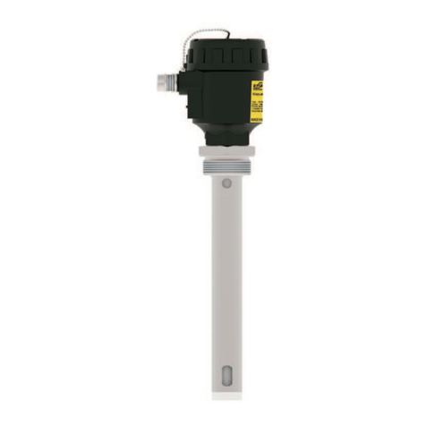
  9. ENSIM SENSORS ECAS 101 User manual

ENSIM SENSORS ECAS 101 User manual

OPERATING
MANUEL
CAPASITIVE LEVEL SWITCH
ECAS
Model :
Model : 82-2021-008
Information in this manual is reviewed and completely reliable. Responsibility is not assumed due to any typing error.
Products in this manual are available only for information purpose and they may be changed without notice.
ECAS 101 / 102 / 103 / 107
ECAS 202 / 203 / 204 / 205 / 20S
ECAS 301 / 304 / 305 / 30D / 30S
ECAS 408A / 408B / 408T / 408Tp / 408Tm
Models :
1
Important Notes:
Used Symbols :
: Caution : Note : Disposal
Please read this manual carefully before installation of the capasitive level switch. User is responsible for accidents and losses arising
from failure to comply with the warnings in this manual.
In the event that capasitive level switch is broken, take measures in order to prevent accidents and losses which can occur in its system.
There is not any fuse and circuit breaker on the instrument; they should have been added to the system by the user.
This manual should be stored in an easily accessible place for subsequent use.
The manufacturer's liability cannot exceed the purchase price of the device according to the law.
Do not make any modification on the instrument and do not try to repair it. Reparation should be made by authorized service staff.
Do not operate the system before making assembly in compliance with the assembly chart related to the instrument.
Products which do not contain label and serial number are considered to be excluded from the warranty scope.
The instrument's useful life, determined and announced by the ministry, is 10 years.
Table of Contents :
General Information...........................................................................................................................................................................2
Installation .........................................................................................................................................................................................5
Failure Detection..............................................................................................................................................................................15
Disassembly of Instrument ............................................................................................................................................................15
Service .............................................................................................................................................................................................15
Recalibration....................................................................................................................................................................................15
Repair................................................................................................................................................................................................15
Disposal ...........................................................................................................................................................................................15
Terms of Warranty ..........................................................................................................................................................................15
Terms of Return ................................................15
1.
2.
3.
4.
5.
6.
7.
8.
9.
10.
2
1. General Information :
1.1. Material Acceptance
Check that there is no damage on the packages during the transportation immediately after the material acceptance. If packages are
damaged, open the packages immediately and check whether products are affected or not, if there is any damage, send your
complaint report to the transporter company and its photocopy to the address of our company.
1.2. Information about Areas of Use
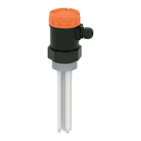
ECAS level switch is a capacitive level sensor for level measurement of conductive liquid, nonconductive liquid, granulated materials with
solid particles, adhesive and acid / base liquids. When a material comes between electrode rod and tank wall, a capacitance change
occurs and when this change exceed adjustment threshold, contact output is delivered.
Designed for difficult process conditions. Models with cooling apparatus can be manufactured for high temperature and pressure conditions.
Calibrations of triggering point and relay operation range can be performed by the user under workplace conditions.
It can be connected horizontally or vertically.
Application Areas
Liquid tanks, food machines, cooling liquid tanks, shipping, glycol tanks, brine, waste water tanks.
Oil tanks, CO2 liquid tanks, high temperature tanks, low-conductive liquids.
Grain silo, cement silo, sand feed, dough, milk powder, organic and plastic granule.
Sticky hot and high viscosity liquid, acid and chemical liquids.
Ambient Conditions: Relative Humidity: 0-98 %RH Ambient temperature: 60C (It is not used under -20 C)
Capacitance definition, assuming two parallel conductive plates are used;
1.3. Working Principle
d
C
R
Isolation
Metal Tank
S
Impedance
Distance
Capacity
Distance
However, there are scarcely any sensor type which this definition
can be pratically utilized. Above Formula can no longer
is reliable especially when residual areas increase due to large
distance (d) (which is usually the case). Thus, measuring
impedance for distance measurements gives more accurate
results than capacitance measurement.
C: capacity , Farad
S: Surface Area , m²
d: Distance , m
eo.er.S
d
C=
e
Excitation applied between 10 KHz250 KHz based on length
for all our models. ( =2 x p x f) Linearity error that may be caused
by conductivity component (R) effect is prevented by electronic
circuit design and mechanical design. Reduced to a level lower than
1ppm, acceptable as zero.
e
Impedance definition Z = R + jL + ( jC )-1
e
R is defined as real component and represent ambient conductivity.
Advantages :
Optionally high temperature-resistant
design.
Easy assembly and sensitivity
adjustment.
No need to clean.
Not affected by foam, liquid splash and
probe coating.
Can be mounted upside down (reverse)
3
2.p.eo.er
In (b/a)
Impedance is calculated by this definition
C=
jLw second component is defined as inductive reactance. This component is present even if we perform capacitive
measurement. However we neglect this. Since we evaluate results based on electrostatic properties of the environment,
no error will occur. Resulting impedance definition is Z= R + (jC )-1.
e
Measurement is made by charge transfer in our capacitive sensors. Total impedance is defined as Z = V / I.
I (current) I = Q/t
Q (Coulomb)
T (sec)
Capacitive reactance we desire to measure is (jC )-1. Meaning that charge and impedance have the same phase.
To summarize, charge transferred to medium is directly proportional with capacitive reactance.
For sensors manufactured as coaxial;
a: Central electrode radius
b: Outer screen radius
L: length
e
e
Excitation applied between 10KHz250KHz based on length for all our models. ( =2xpxf)
Linearity error that may be caused by conductivity component (R) effect is prevented by electronic
circuit design and mechanical design. Reduced to a level lower than 1ppm, acceptable as zero.
-20 40 80 2000
16
20
100
-40 150
Pprocess (bar)
T process (°C)
Process Pressure / Temperature Chart
With Cooling Apparatus
40
80
0-40 100 200150
T ambiance (°C) Ambiance Pressure / Temperature Chart
With Cooling Apparatus
T process (°C)
4
1.4. Technical Specifications and Material Knowledge
1.5. Label Information :
1 NA / NK x5 A / 250 VAC Relay
Opt. Peek, CeramicPTFE, PFA
PBT (Std.)
Ops. Aluminum Injection, Stainless Steel
er
24 VDC
(-) 1 bar...100 bar (Depending on the model.)
304 St.St. Opt. 316 St.St.
1,6
With LED-Power and Contact LED
Max. 1 W
Terminal
EMC, Low Voltage
285 g. for ECAS 101
(-) 20 °C...(+) 60 °C
PBT
- IP 66 , Alüminyum , Pas. Çelik IP 65
Max. 40 Nm
Max. 500 V
(-)40/(+)150°C (Depending on the model)
200°C with cooling apparatus
230°C with PEEK isolation
400°C with ceramic isolation
Supply
Signal Output
Working Pressure
Min.Di-Electric Constant
Measurable Metarial
Connection Material
Display
Power Consumption
Protection Class(EN60529)
Test
Max. Tensile Force
Weight
Isolation Material
Housing Material
Working Temperature
Ambient Temperature
Electrical Connection
Isolation
Conductive liquids, refrigerants
Non-conductive liquids
Solids particulate materials
Adhesive and acid/basic liquids
LEVEL SWITCH
Type
Output
Supply
S.N.
:
:
:
:
ECAS101-Ø10-300mm-0-0006-11- 5239-066-002-00/0
1XNO/NC
24 VDC ± %10
IE20060002-0001
Model
Manufacturer
Website
Serial
Number
www.ensim.com.tr
MADE IN TURKIYE
Warning
Symbols
Warning
Symbols
Approval SignManufacturer Brand Product Name
Product Label :
Protection Case:
Material : 304 Stainless Steel
Welded manufacturing
Opens - Closes Hinged
To Protect Against external conditions.
5
1.6. Target Group
This operating manual has been prepared for qualified technical personnel.
1.7. Security Notes
Please consider below notes for avoiding hazardous cases around operator and its environment.
Only users that authorized in work safety and whom also have read the manual should setup this equipment.
Work safety , accident avoid regulations and national/local setup standards must be meet.
Equipment should only be used in stated specifications.
Equipment must only be mounted while there is no pressure.
1.8. Package and package contents
Please check whether you have taken delivery of below listed content completely or not and check its conformity with criterions in your order:
*Capasitive Level Switch
*This operating manual
2. Installation :
2.1. General Notes :
The device installation is in 2014 / 34 / EU criteria to ensure the safety of atmosphere and people from explosions, must only be done by staff who
knows the safeguards.
Do not apply force to the instrument during the installation!
Do not use the Capacitive Level Switch with a greater pressure than recommended pressure.
Do not forget that instrument is precise, carry it carefully and prevent not to be damaged.
It should be guaranteed that there are not any magnetic particles.
The Max. working pesure should not be exceeded.
2.2. General Installation Stages
*Remove Capacitive Level Switch from the box carefully
*Check whether gasket is appropriate for fluid or not. If is not appropriate, contact with the producer.
*Then, apply below mentioned explanations according to structure of the design.
2.3. Special Notes
*Please ensure that there is no mechanical stress on the shaft following installation. Such case will cause slipping in thecharacteristic curve.
*Capacitive Level Switch must be placed upright or horizontal.
*Allocate valve certainly in the process connection while instrument is used.
*Allocate blowdown valve under bottom flange for blowdown.
*If instrument is mounted outside and if there is any danger of lightning or
excessive pressure, take preventive measures by taking necessary measures.
*In the operating conditions, Capacitive Level Switch may be hot according
to situation of fluid, in this case, do not touch the indicator, otherwise your skin is damaged.
*The grounding product must be done properly. (can be done outside or in housing)
2.4. Installation For Mechanical Connections
*Use appropriate O-Ring or gasket for tightness.
*Ensure that its surface is clean and smooth.
*Assemble the instrument manually.
*Connect the contacts as shown in the figure.
(For stainless steel models max. 30Nm)
6
Trigger Point
Sensation Zone
24 VDC
NA
NK
Com
+-
Sample Model :
Cooling :
27 HEX
1/2 BSP
PFA
L
68
For Max. 200 °C
2.5. Electrical Installation
Make the electrical connection of the instrument according to details on its label, table and cable figures in this manual
RlyLED: Relay active during normal operation; means operation continues during
calibration. Flashes continuously in normal operation mode if relay is
active and blinks in calibration mode. It is red colored.
PwrLED: Means there is no sensor failure during normal operation, and means
desired measurement values are saved in memory during calibration.
Operates by flashing. If light is continuous, it indicates failure. It is gren colored.
CAL - S Button: Used to acquire High Level-span-value during calibration.
CAL - Z Button: Used to acquire Low Level-zero-value during calibration.
TST Button: During normal operation, functions as Relay Test; during calibration,
performs saving to nonvolatile memory of Zero-Span, the values previously acquired
by S and Z button, function.
LVL - C Pot: Adjusts relay triggering point between Zero-Span values.
LVL - F Pot: Performs as fine tuning for triggering point. Adjustment field is equal
to +/- 5% of the point adjusted by C Pot (total 10%).
DIF Pot: Adjusts Release level of the relay activated by C/F Pot.
Highest adjustable value is equal to half (50%) of the operation region specified by
Z and S. Meaning that, when DIF Pot is at 100% and relay is pulled, the level to
release it shall be reduced as half of the total scale.
*
*
*
*
*
*
*
*
Indification and Calibtarion :
Electronic Unit with Cable:
Electronic unit and sensor component can be separated by a cable that protected against
exterior conditions for easy calibration on site. Thanks to the properties of cable, easy assembly
for user is possible without affecting capacitive measurement.
Relay working range
adjustable. (50%)
L
2.6. Mechanical Dimensions
7
CONDUCTIVE LIQUIDS
Sample Models
27 HEX
PFA
L
1/2BSP
(-) 1 bar...(+) 100 bar
(-) 40 °C...(+) 150 °C
Fully Insulated Probe
Conductive Tank
ECAS 101
L= 250 mm. (Std) Max. 4 m.
200
St. St.
St. St.
2BSP
70 HEX
Fully Insulated Rope
Conductive Tank
L= 1 m. (Std) Max. 32 m.
ECAS 107
Ø40
(-) 1 bar...(+) 60 bar
(-) 40 °C...(+) 150 °C
PFA
L
Plastic
ECAS 102
Fully Insulated Coaxial Probe
Insulated Tank
L= 250 mm. (Std) Max. 4 m.
70 HEX
L
2BSP
PFA
(-) 1 bar...(+) 100 bar
(-) 40 °C...(+) 150 °C
St. St.
Plastic
PFA
3/4BSP
32 HEX
L
L= 250 mm. (Std) Max. 1 m.
Fully Insulated Coaxial Probe
Insulated Tank
ECAS 103
(-) 1 bar...(+) 100 bar
(-) 40 °C...(+) 150 °C
St. St.
Plastic
200
St. St.
Ø40
St. St.
1 1/2BSP
60 HEX
PFA
Fully Insulated Rope
Conductive Tank
(-) 1 bar...(+) 60 bar
(-) 40 °C...(+) 150 °C
L= 1 m. (Std) Max. 16 m.
ECAS 107
L
Plastic Plastic
80
80
11
8
ECAS 202
LOW CONDUCTIVE LIQUIDS
70 HEX
L
2BSP
St.St.
32 HEX
L
3/4BSP
ECAS 203
St.St.
St.St.
1 1/2BSP
60 HEX
200
Ø40
St.St.
ECAS 204
St.St.
L
ECAS 204
2BSP
70 HEX
200
Ø40
St.St.
St.St.
St.St.
L
41 HEX
L
1BSP
Ø12
PTFE
ECAS 205
L= 250 mm. (Std) Max. 6 m.
(-) 1 bar...(+) 60 bar
(-) 40 °C...(+) 150 °C
St.St.
ECAS 20S
60 HEX
L
1 1/2BSP
St.St.
Alüminyum
290
Ø38
Plastic Plastic Plastic
L= 250 mm. (Std) Max. 4 m.
(-) 1 bar...(+) 100 bar
(-) 40 °C...(+) 150 °C
L= 250 mm. (Std) Max 1 m.
(-) 1 bar...(+) 100 bar
(-) 40 °C...(+) 150 °C
L= 250 mm. (Std) Max. 4 m.
(-) 1 bar...(+) 25 bar
(-) 40 °C...(+) 400 °C
L= 1 m. (Std) Max. 16 m.
(-) 1 bar...(+) 60 bar
(-) 40 °C...(+) 150 °C
L= 1 m. (Std) Max. 32 m.
(-) 1 bar...(+) 60 bar
(-) 40 °C...(+) 150 °C
Partly Insulated Coaxial Probe
Conductive / Insulating Tank
Partly Insulated Coaxial Probe
Conductive / Insulating Tank
Partly Insulated Probe
Conductive Tank
Partly Insulated Rope
Conductive Tank
Partly Insulated Rope
Conductive Tank
Partly Insulated Coaxial Probe
Conductive / Insulating Tank
Plastic Plastic Plastic
9
PTFE
Ø21
80
L
8050
L
ECAS 301
L= 250 mm. (Std) Max. 1 m.
(-) 1 bar...(+) 25 bar
(-) 40 °C...(+) 150 °C
SOLID PARTICULATE MATERIALS
41 HEX
1BSP 41 HEX
ECAS 305
St.St.
St.St.
Antistatic
For Materials
PTFE
Ø40
50 80
200
L
60 HEX
1 1/2BSP
PTFE
St.St.
St.St.
ECAS 304
L= 1000 mm. (Std) Max. 16 m.
(-) 1 bar...(+) 25 bar
(-) 40 °C...(+) 150 °C
L= 380 mm. (Std) Max. 1 m.
ECAS 30D ECAS 30S
Seramic Insulated Probe
Insulating Tank
41 HEX
Ø21
1BSP
St.St.
St.St.
Ø12
80508050
L
Aluminium
51 HEX
215
High Temperature Version
Seramic
60 HEX
Ø12
L
180
St.St.
L= 300 mm. (Std) Max. 4 m.
Plastic Aluminium
L= 250 mm. (Std) Max. 6 m.
(-) 1 bar...(+) 25 bar
(-) 40 °C...(+) 150 °C
(-) 1 bar...(+) 25 bar
(-) 40 °C...(+) 200 °C
(-) 1 bar...(+) 25 bar
(-) 40 °C...(+) 400 °C
Compled Insulated Probe
Conductive Tank
Partly Insulated Probe
Conductive Tank
Double Partly Insulated Probe
Insulating Tank
Partly Insulated Rope
Conductive Tank
1BSP
1 1/2BSP
10
ADHESIVE AND ACID / BASIC LIQUIDS
70 Hex
2 BSP
L
Aluminium
PFA
St.St.
L
70 Hex
Aluminium
St.St.
St.St.
PTFE
L
70 Hex
Delrin
Plastic
St.St.
St.St.
PFAPFA
2 BSP
Plastic
PTFE
70 Hex
PVC Coaxial
Plastic
PVC
70 Hex
PFAPFA
1 BSP
Plastic
PVDF
46 Hex
L
L
L
L= 250 mm. (Std) Max. 4 m.
(-) 1 bar...(+) 100 bar
(-) 40 °C...(+) 150 °C
L= 250 mm. (Std) Max. 6 m.
(-) 1 bar...(+) 60 bar
(-) 40 °C...(+) 150 °C
L= 250 mm. (Std) Max. 6 m.
(-) 1 bar...(+) 25 bar
(-) 20 °C...(+) 80 °C
L= 250 mm. (Std) Max. 1 m.
(-) 1 bar...(+) 60 bar
(-) 40 °C...(+) 150 °C
L= 250 mm. (Std) Max. 1 m.
(-) 1 bar...(+) 60 bar
(-) 40 °C...(+) 150 °C
L= 250 mm. (Std) Max. 1 m.
(-) 1 bar...(+) 6 bar
(-) 40 °C...(+) 60 °C
2 BSP
ECAS 408A
Double Probe (Single Fully Insulated)
Conductive / Insulating Tank
ECAS 408B
Double Partly Insulated Probe
Conductive / Insulating Tank
ECAS 408B
Double Partly Insulated Probe
Conductive / Insulating Tank
ECAS 408T
Double Partly Insulated Probe
Conductive / Insulating Tank
ECAS 408Tp
Double Partly Insulated
PVC Coaxial Probe
Conductive / Insulating Tank
ECAS 408Tm
Double Partly Insulated Probe
Conductive / Insulating Tank
2 BSP
11
2.7. Parts
Housing
MATERIALS PROTECTION
CLASS
TEMPERATURE
(oC)
TYPE
Plastic (PBT)
Plastic (PVDF)
Plastic (PBT)
Aluminium
Aluminium
Aluminium
Stainless Steel
DIMENSION
a x b x c (mm)
ORDER
CODE
B10p
B11p
B20p
B10x
B20x
B22x
B101x
IP 65
IP 65
IP 65
IP 65
IP 66
IP 66
IP 65
(-) 40...(+) 150
(-) 40...(+) 120
(-) 40...(+) 150
(-) 40...(+) 150
(-) 40...(+) 200
(-) 40...(+) 200
(-) 40...(+) 150
96 x 77
96 x 77
132 x 104
96 x 77
132 x 104
114 x 112
108 x 79
050
053
103
503
603
750
851
96
77
B10p
96
77
B10x
96
77
B11p B101x
108
79
Stainless SteelAluminiumPlastic Plastic
B20p B20x
AlüminyumPlastik
B22x
Alüminyum
104
132
104
132 114
102
Insulated Probe
Cap
Elektronic Unit
Housing
Coaxial Probe
Cable Gland
Connection
12
2.8.
Housing
Mechanical Connection :
Dairy d
d1
D
A
HEX
B
b
Thread
Flanged
b
D1
D
Dimension
B
Hex
(mm)
Thread Lenght
b (mm)
1/2 BSP
3/4 BSP
1 BSP
1 1/4 BSP
1 1/2 BSP
2 BSP
27
32
41
51
60
70
14
14
23
23
23
23
(ISO228-1)
Order
Code
0004
0005
0006
0008
0009
0012
PN 40 D (mm)
DN 25
DN 32
DN 50
DN 80
DN 100
115
140
165
200
235
85
100
125
160
190
(ISO1092-1)
D1 (mm) b (mm)
18
20
20
20
24
Order
Code
0702
0703
0705
0707
0708
150 LBS D (mm)
DN 50
DN 65
DN 80
DN 100
152,4
177,8
190,5
228,6
121
139,7
152,4
157,2
(ANSI B16.5)
D1 (mm) b (mm)
19
22,2
23,8
23,8
Order
Code
1005
1006
1007
1008
PN 16 D (mm)
DN 25
DN 32
DN 50
DN 80
DN 100
165
140
165
200
220
85
100
125
160
180
D1 (mm) b (mm)
16
16
18
20
20
(ISO1092-1)Order
Code
0502
0503
0505
0507
0508
Clamp
b
D
Measurement b
(mm)
DN 32
DN 50
DN 65
50,5
64
91
15
17
17
(ISO2852)
D (mm)
1501
1502
1503
Order
Code
D (mm)
DN 40
DN 50
DN 100
56
68
121
48
61
114
d1 (mm) A (mm)
13
14
20
Measurement
DN 40
DN 50
DN 100
Measurement
1600
1601
1602
Order
Code
13
2.10. Order Form :
OUTPUT
7
ECAS 101 - Ø 10 - 300 mm - 0 - 0006 - 11 - 050 - 066 - 002 - 00 / 0
For conductive liquids , L= 300 mm, 1 BSP , Relay Output, Aluminium Housing , Ø 10 Probe
SAMPLE
Relay Output NA/NK (5A)......................................11
8
Special...........................................................................x
9
INSULATION MATERIAL
10
PBT........................................................................065
PTFE.....................................................................066
PFA........................................................................067
PEEK.....................................................................068
11
13
12
PROCESS TEMPERATURE
6
STEM LENGHT
5
MODEL ECAS
...............................................................................mm
Order Form :
Please consider sample models when coding.
OPTIONAL
None...................................................................../ 0
With By - Pass Tube............................................... / T
Shetter (For the outside of the tank) 304 St. St.../ K6
Seperable Electronic Unit................................................../ S
Wall Apparatus................................................................../ W
Special................................................................................/ x
CONNECTION MATERIAL
304 Stainless Steel ...............................................001
316 Stainless Steel ...............................................002
Brass......................................................................041
PVC........................................................................061
Polypropylene........................................................062
HOUSING
Aluminium
Housing , B20x .............................................603
Aluminium
Housing , B22x .............................................750
Stainless Steel
Housing , B101x.....................................800
Special..................................................................................x
Plastic Housing , B10p .........................................050
Plastic Housing , B11p .....................................053
Plastic Housing , B20p .........................................103
Aluminium
Housing , B10x ...................................503
Conductive Liquids....................................................1
Non-Conductive Liquids ...........................................2
Solids Particulate Materials..................................................3
Adhesive and Acid / Basic Materials...............................4
CERTIFICATE
None...........................................................................0 (EN10204-3-1)Material Certification..................................1
PROBE TYPE (MAX. LENGHT)
Single Probe - Insulated (Max. 4 m.) ..................... 1
Single Probe - Coaxial (Max. 4 m.) Ø 38 ............... 2
Single Probe - Thin Coaxial (Max. 1 m.), Ø 21 ...... 3
Rope - Non-Insolated (Max. 32 m.) ........................ 4
Single Probe - Non-Insolated (Max. 6 m.) .............. 5
Single Probe - High Temperature (Max. 4 m.) ........6
Rope - Insulated (0 ... 32 m.)................................... 7
Double Probe - Single Insulated (Max. 4 m.) ............................. 8A
Double Probe - Non-Isolated (Max. 6 m.) .................................. 8B
Double Probe - Double Insulated (Max. 4 m.) ........................... 8T
Double Probe - Double Insulated, PVC Coaxial (Max. 4 m.) .. 8Tp
Double Probe Thin - Double Insulated (Max. 1 m.) ................. 8Tm
Ceramic Insulated Probe (Max. 4 m.) ...........................................S
Double Probe - Insulated (Max. 4 m.) ............................. D
Special............................................................................................ x
PROBE DIAMETER (Ø)
150 °C (Standard).....................................................0
200 °C with Cooling Apparatus ...............................1
(-) 196 °C For Cyrogenic Tank ..........................................2
230 °C with Peek Insulated .................................................3
400 °C with Seramic Insulated ............................................4
CONNECTION
ELECTRICAL CONNECTION
With Terminal...........................................................00 Special...................................................................................x
Polyamide........................................................................069
Seramic............................................................................070
Rubber..............................................................................081
FKM..................................................................................084
Steel Shielded Cable (Max. 350 °C)...............................048
Special..................................................................................x
Delrin.................................................................................063
PVDF.................................................................................064
PBT...................................................................................065
PTFE.................................................................................066
Special...................................................................................x
Thread (ISO 228-1) Clamp (ISO 2852) ISO Flange(1092-1) ASA Flanged (B16.5)
1/2 BSP..............0004
3/4 BSP ...............0005
1 BSP....................0006
1 1/2 BSP..............0010
2 BSP...................0012
1/2 NPT............0203
3/4 NPT............0204
DN 32 - PN 16...1501
DN 50 - PN 16...1502
DN 65 - PN 16...1503
DN 25 - PN 16...0502
DN 32 - PN 16...0503
DN 50 - PN 16...0505
DN 80 - PN 16...0507
DN 100 - PN 16...0508
DN 50 - 150lb ... 1005
DN 65 - 150lb ... 1006
DN 80 - 150lb ... 1007
DN 100 - 150lb ... 1008
ISO Flange (1092-1)
DN 25 - PN 40...0702
DN 32 - PN 40...0703
DN 50 - PN 40...0705
DN 80 - PN 40...0707
DN 100 - PN 40...0708
Ø 10 mm (Std.).........................................................10 Ø 8 mm ..............................................................................08
Ø 12 mm ............................................................................12
14
2.11. WARNING !!!
Please pay attention to following matters in order to operate your flow switch properly.
Do not remove the plastic parts
of the bottom of the switch body ,
do not loosen.
Do not pull the cable strongly,
otherwise the characteristics
might be changed.
Do not connect the switch in reverse.
Their characteristics may vary.
Vibration might be caused instability. Do not fasten switch reversely ,
otherwise its characteristics
might be changed.
Excess current , to be drawn as
a result of direct connection to motor,
may burn relay of switch
Please do not dip cables
potting into liquids,otherwise
instulation problem may cause.
Do not fasten switch reversely ,
otherwise its characteristics
might be changed.
Please do not drop ,
otherwise the characteristics
might be changed.
When connecting the switch to the tank
Connect with 20 degree angle.
Switch from 30 cm each other
do not connect close
Please keep away from magnetic materials
like iron board ; otherwise the
characteristics might be affected
15
Your device must be repair only at an outhorized serviced.
If you find an error, try to eliminate it by using this table or send the instrument to our service address for repair.
The instrument should be repaired only by authorized service! Serial number shall be indicated to the authorized service center.
4. Disassembly of Instrument
Instrument should be disassembled while feeding and pressure is not available!
5. Service
6. Re-Calibration
During long period usage of capacitive level switch, there might be deviations on measurements. In those cases, recalibration is recomended. Re-calibration could
be made by your technical staff or you could send to manufacturer company. According to IEC 60017, ex proof devices must be go through detailed inspection every
3 yearS from purchase date.Respobsibility of inspections are belong to the user ( IEC: International Electrotechnical Commission)
7. Repair  Manufacturer Address
If irreparable breakdowns occur, the instrument should be sent to us for repair purpose. Before this, the instrument should be cleaned carefully and packaged
so as not to be broken. Furthermore, you should also add a detailed explanation which describes the breakdown while instrument is sent. If your instrument
contacts with harmful substances, decontamination report should be also sent additionally. In the event that instrument does not have any decontamination
report or our service department has doubts about instrument, repair process will not start until an acceptable report is sent.
8. Disposal
The instrument should be disposed according to 2002/96/EC and 2003/108/EC European Directives (waste electrical and electronic instruments).
Waste electrical and electronic equipment should not be mixed with domestic wastes!
If the instrument has contacted with harmful substances, special attention should be paid for its disposal!
9. Terms of Warranty
The instrument has warranty legally for 24 months after delivery date. Warranty demands are not accepted in case of inappropriate operation, damage on the
instrument or any modification on the instrument.
10. Terms of Return
In the return of materials, user should send an open list related to damage or problem, malfunction of the material to be returned or its operation in the different
modification, with the instrument. If it is required to return the material, used in the dangerous, corrosive or toxic fluid, in this case, used part should be cleaned
very carefully. Security of personnel should be ensured. All products to be returned should be sent to our company address, which
we have stated.
The instrument does not require maintenance. If it is desired, residue accumulated inside should be blown according to kind of fluid and instrument can be cleaned
with soft cleaning solutions. Measures should be taken during the disassembly.
If the instrument contacts with hazardous substances, necessary measures should be taken for decontamination!
Service -Manufacturer Company Name and Address:
LONCA MAK. SAN. TÝC. A.Þ. Ferhatpaþa Mah. Gazipaþa Cad. No: 104A Ataþehir - ÝSTANBUL - TÜRKÝYE
Tel:+90 216 50 50 555 Faks:+90 216 515 45 84 E-Mail: [email protected] Web: www.ensim.com.tr
Power Led does not work.
* Supply voltage may not be work.
*Power led might be faulty.
* Electronic card might be faulty due to supply.
* The supply voltage must be checked.
* Please apply to service.
Relay does not output
* The applied process may not be suitable for the probe
* Grounding connection might be poor or disconnected
* The low voltage might be supply.
* Grounding might be done correctly.
* The applied process may not be suitable for the probe.
* The Teflon coating on the product probe might be
damaged.
* Grounding might be done correctly.
Relay provides continuous output.
Non-Calibration
* Trimpot might be deformed.
* The applied process may not be suitable for the probe.
* Grounding might be done correctly.
* Proper probe structure and product detection must be perfomed.
* The grounding connection check.
* Supply must be checked.
* Please check grounding line.
* Proper probe structure and product detection must be perfomed.
* Protection of external coatings of probes.
* Please check grounding line.
* Please apply to service.
* Proper probe structure and product detection must be perfomed.
* Please check grounding line.
Breakdown Probable cause Failure detection\correction
3. Failure Delection

This manual suits for next models

17

Other ENSIM SENSORS Switch manuals

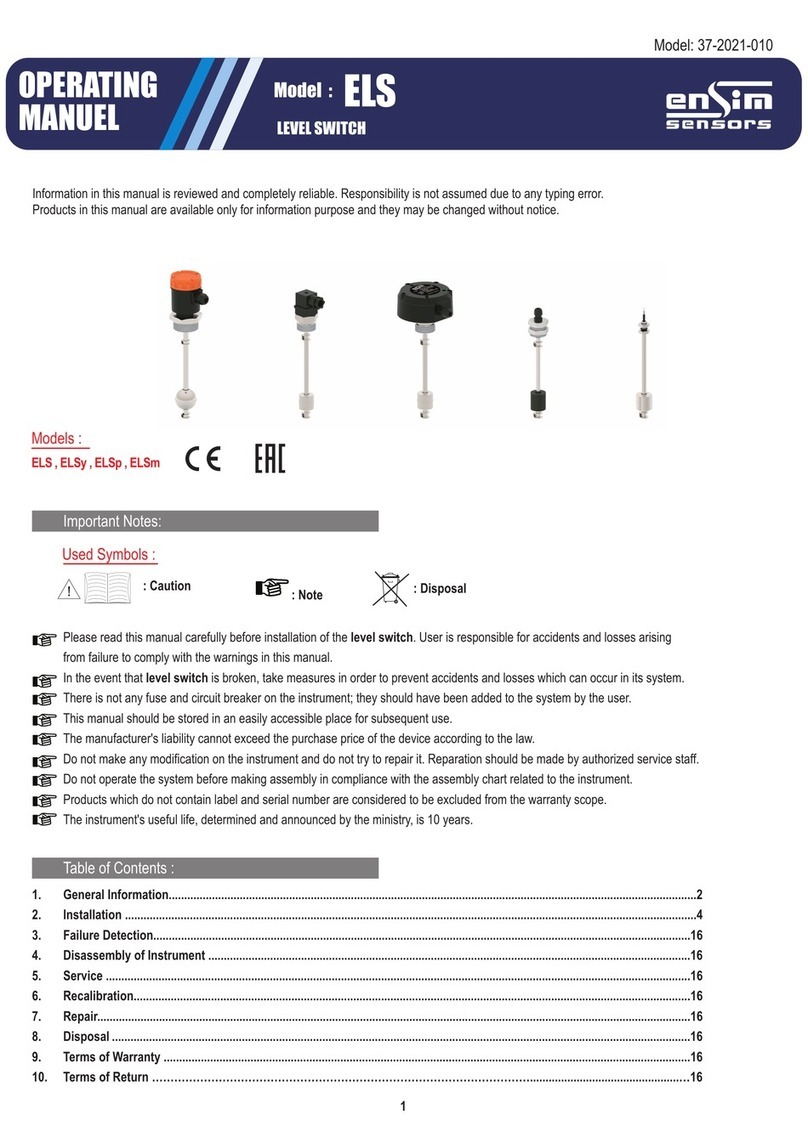
ENSIM SENSORS ELS User manual

ENSIM SENSORS

ENSIM SENSORS ELS User manual

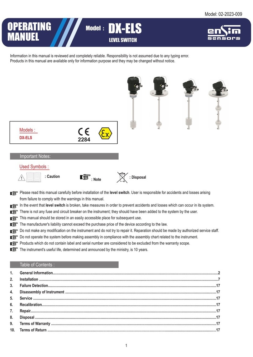
ENSIM SENSORS DX-ELS Series User manual

ENSIM SENSORS

ENSIM SENSORS DX-ELS Series User manual

ENSIM SENSORS DX-ELB 11 User manual

ENSIM SENSORS

ENSIM SENSORS DX-ELB 11 User manual

ENSIM SENSORS DX-ELS User manual

ENSIM SENSORS

ENSIM SENSORS DX-ELS User manual

ENSIM SENSORS ELC 21d User manual

ENSIM SENSORS

ENSIM SENSORS ELC 21d User manual

ENSIM SENSORS ELT User manual

ENSIM SENSORS

ENSIM SENSORS ELT User manual

ENSIM SENSORS ELP User manual

ENSIM SENSORS

ENSIM SENSORS ELP User manual

ENSIM SENSORS DX-ELT User manual

ENSIM SENSORS

ENSIM SENSORS DX-ELT User manual

ENSIM SENSORS ELM Series User manual

ENSIM SENSORS

ENSIM SENSORS ELM Series User manual

ENSIM SENSORS EFS User manual

ENSIM SENSORS

ENSIM SENSORS EFS User manual

ENSIM SENSORS ISS 04 User manual

ENSIM SENSORS

ENSIM SENSORS ISS 04 User manual

ENSIM SENSORS DX-ECAS Series User manual

ENSIM SENSORS

ENSIM SENSORS DX-ECAS Series User manual

ENSIM SENSORS ELP Series User manual

ENSIM SENSORS

ENSIM SENSORS ELP Series User manual

ENSIM SENSORS DX-ELF 101 User manual

ENSIM SENSORS

ENSIM SENSORS DX-ELF 101 User manual

Popular Switch manuals by other brands

Vimar 0K03906 Series manual

Vimar

Vimar 0K03906 Series manual

D-Link Dis-200G Series Cli reference guide

D-Link

D-Link Dis-200G Series Cli reference guide

Tesla smart HKS0801A1U user manual

Tesla smart

Tesla smart HKS0801A1U user manual

OpenVox FD182 user manual
OpenVox

OpenVox FD182 user manual

Cables to Go TRUlink 35566 user guide

Cables to Go

Cables to Go TRUlink 35566 user guide

ANTAIRA Lanolinx LNX-1002GN user manual

ANTAIRA

ANTAIRA Lanolinx LNX-1002GN user manual

Cisco SD208T-NA Administration guide

Cisco

Cisco SD208T-NA Administration guide

D-Link DKVM-4U Quick installation guide

D-Link

D-Link DKVM-4U Quick installation guide

Omega Engineering LVUN-600 user guide

Omega Engineering

Omega Engineering LVUN-600 user guide

IP-COM G3224P user guide

IP-COM

IP-COM G3224P user guide

Draytek VigorSwitch P2500 quick start guide

Draytek

Draytek VigorSwitch P2500 quick start guide

Humminbird 531870-1_A Installation

Humminbird

Humminbird 531870-1_A Installation

Aruba S3500-24P installation guide

Aruba

Aruba S3500-24P installation guide

iNels RFSOU-1 manual

iNels

iNels RFSOU-1 manual

Goobay 51445 user manual

Goobay

Goobay 51445 user manual

Vetra USB-802-IN2D-DE User instructions

Vetra

Vetra USB-802-IN2D-DE User instructions

DIGITAL YACHT NS5 Installation and instruction manual

DIGITAL YACHT

DIGITAL YACHT NS5 Installation and instruction manual

ABB DWTL1 user manual

ABB

ABB DWTL1 user manual

manuals.online logo
manuals.online logoBrands
  • About & Mission
  • Contact us
  • Privacy Policy
  • Terms and Conditions

Copyright 2025 Manuals.Online. All Rights Reserved.