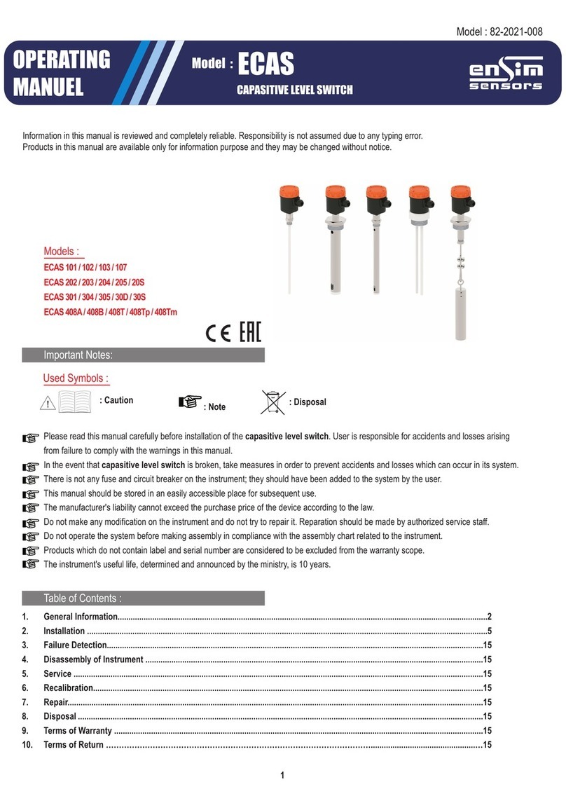
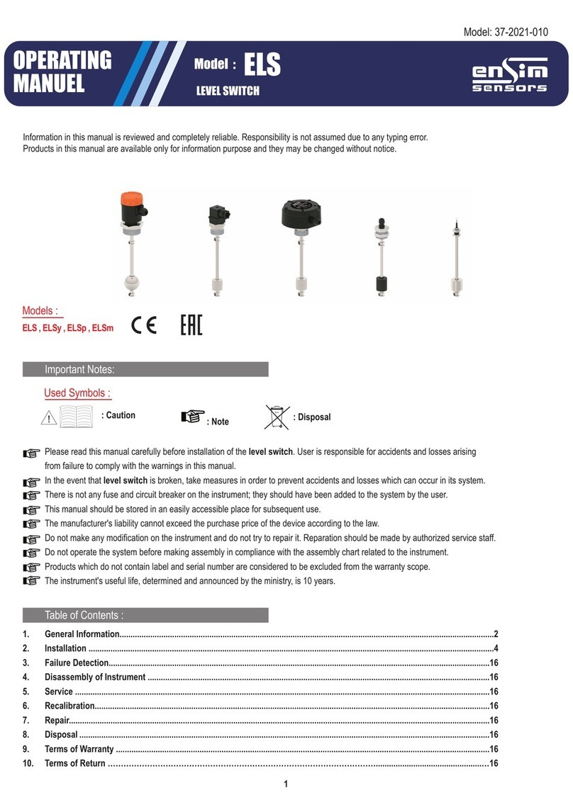
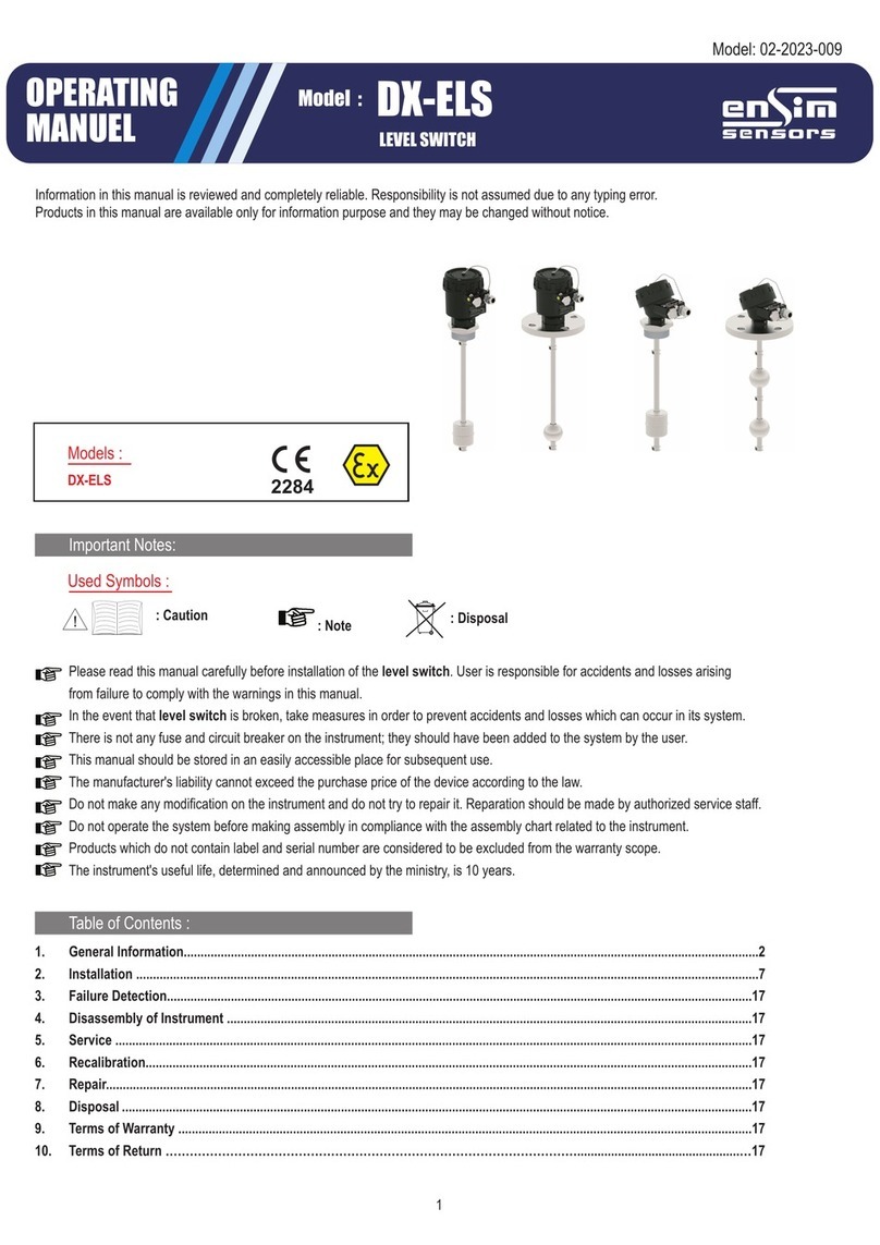
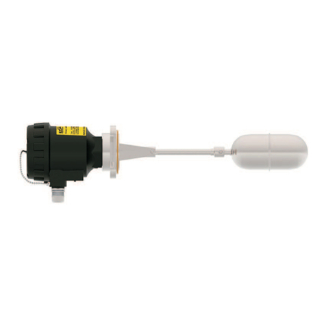
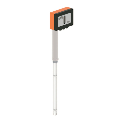
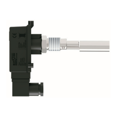
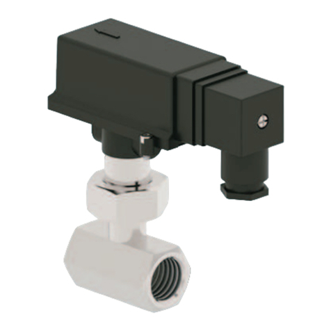
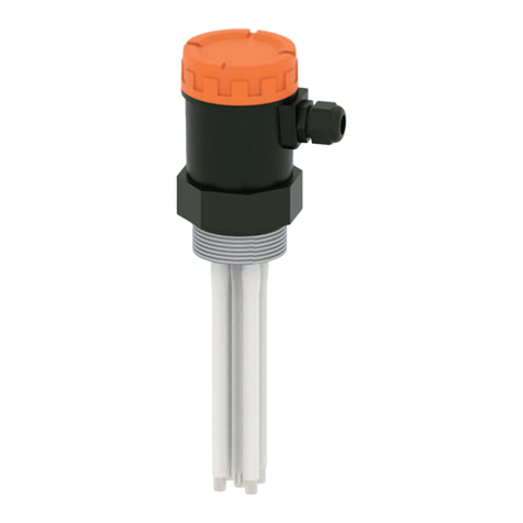
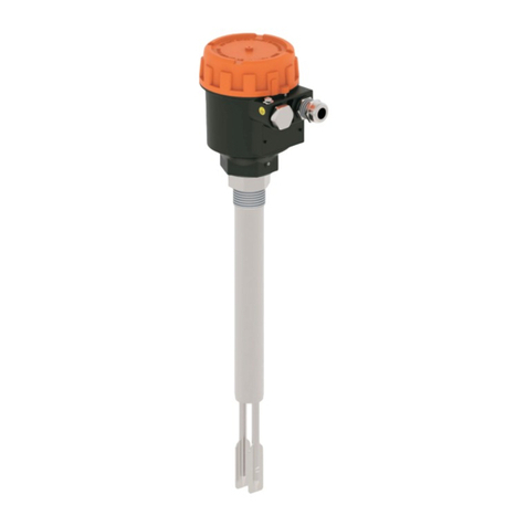
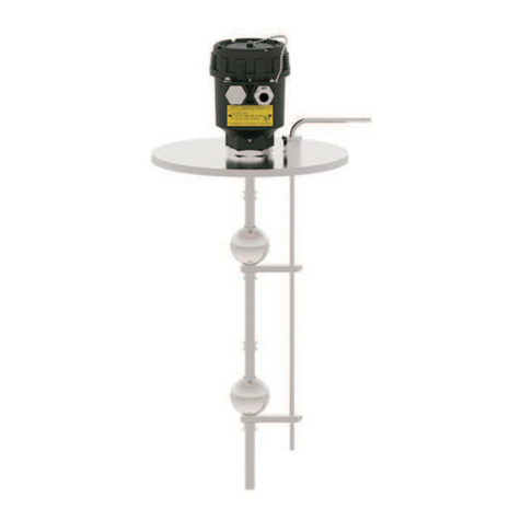
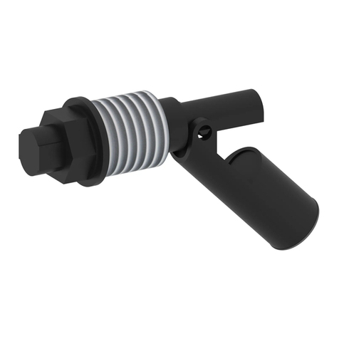
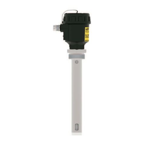
ENSIM SENSORS ELP Series User manual
OPERATING
MANUEL
LEVEL SWITCH
ELP
Model :
Model : 11-2017-004
Information in this manual is reviewed and completely reliable. Responsibility is not assumed due to any typing error.
Products in this manual are available only for information purpose and they may be changed without notice.
Models :
1
ELP 31
ELP 11
ELP 32
ELP 32s
ELP 33
ELP 81p
ELP 11 , ELP 26
ELP 31 , ELP 32 , ELP 32s , ELP 33
ELP 81p , ELP 81 , ELP 82
ELP 02a / 02b / 03a / 03b
ELP 04a / 04b / 08a / 08b
ELP 02a / 02b
ELP 03a / 03b
ELP 04a/ 04b
ELP 08a / 08b
ELP 81 /82
Important Notes:
Used Symbols :
Please read this manual carefully before installation of the level switch. User is responsible for
accidents and losses arising from failure to comply with the warnings in this manual.
In the event that level switch is broken, take measures in order to prevent accidents and losses which
can occur in its system.
There is not any fuse and circuit breaker on the instrument; they should have been added to the system
by the user.
This manual should be stored in an easily accessible place for subsequent use.
Do not operate the system before making assembly in compliance with the assembly chart related
to the instrument.
Do not make any modification on the instrument and do not try to repair it. Reparation should be made
by authorized service personnel.
The instrument's useful life, determined and announced by the ministry, is 10 years.
Products which do not contain label and serial number are considered to be excluded from the warranty scope.
: Caution : Note
Table of Contents :
1. General Information...........................................................................................................................................2
2. Installation ..................................................................................................................................................3
3. Failure Detection..............................................................................................................................................6
4. Disassembly of Instrument ..................................................................................................................................6
5. Service ......................................................................................................................................................6
6. Recalibration...............................................................................................................................6
7. Repair....................................................................................................................................................................6
8. Disposal................................................................................................................................................6
9. Terms of Warranty .....................................................................................................................................6
10.Terms of Return ..............6
: Disposal

2
REED RELAY
..
1. General Information :
1.1. Material Acceptance
Check that there is no damage on the packages during the transportation immediately after the material acceptance. If packages are
damaged, open the packages immediately and check whether products are affected or not, if there is any damage, send your
complaint report to the transporter company and its photocopy to the address of our company.
1.2. Information about Areas of Use
It should be used in allowed using medium and application areas! It is not used in the corrosive mediums,
ambient with explosive and flammable material. Conformity with medium to be measured should be also taken into consideration.
Responsibility is not assumed in case of inappropriate use, modification and injure, and such cases are not covered by warranty.
Ambient Conditions: Relative Humidity: 5-95 %RH Ambient temperature: 70C (It is not used under -5 C)
1.3. Operating Princible
ELP level switches are used for checkin level of tank. It is preferred by machine manufacturers, especially in terms of its ease ofg use and
economy. The ELP level switched can be mounted in litte places because of their mini design. The switches are made by stainless steel
material and so can be used in various liquids.
When magnetic field of magnet in the float is aligned withreed sensor in the tube , it opens or closes
the electric circuit.When float moves away , sensor reverts back ( upon demand , drawn contact may be made).
Level informationcan be assessed with a relay circuit.
CLOSE
OPEN
RING
MAGNET
REED RELAY
CLOSE
OPEN
MAGNET

3
ELP 02a / 02b
ELP 03a / 03b
ELP 04a / 04b
ELP 08a / 08b
Özellikleri :
PP
PP
PP
(-)40/+80C
Atm.
0.7
Cable
1 Std.
SPST-NO
Liquid Level Relay
PP
PP
PP
(-)20/+80C
Atm.
0.7
Cable
1 Std.
SPST-NO
Liquid Level Relay
180 VDC / 130 VAC
0,7 A
10 W / VA
1 A
10 W / VA
180 VDC / 130 VAC
ELP 11
ELP 33ELP 31
PP
PP
P10
(-)20/+80°C
1/2" NPT
4
0.75
Cable
1 Std.
SPST-NO
0,7 A
10 W / VA
180 VDC / 130 VAC
Liquid Level Relay
PVDF
PVDF
P10
(-)30/+120C
1/2" NPT
2
0.85
Cable
1 Std.
SPST-NO
0,7 A
10 W / VA
180 VDC / 130 VAC
Liquid Level Relay
ELP 32s
Liquid Level Relay
ELP 32
PP / PBT
PP / PBT
P10
(-)20/+80C
M16
4
0.75
Cable
1 Std.
SPST-NO
PP
PP
P10
(-)20/+80°C
R1
4
0.75
DIN43650C Socket, P03
1 Std.
SPST-NO
180 VDC / 130 VAC
0,7 A
10 W / VA
1 A
10 W / VA
180 VDC / 130 VAC
Liquid Level Relay
1.4. Technical Specifications :
Float Material
Wetted Parts Material
Pipe Material
Working Temperature
Max. Pressure (Bar)
Min. Density (g/cm3)
Electrical Connection
Number of Float
Number of Contact
Contact Current
Max. Contact Power
Max.Switching Voltage
Optional
Float Material
Wetted Parts Material
Float Type
Working Temperature
Mechanical Connection
Max. Pressure (Bar)
Min. Density (g/cm3)
Electrical Connection
Number of Float
Number of Contact
Contact Current
Max. Contact Power
Max.Switching Voltage
Optional
Float Material
Wetted Parts Material
Float Type
Working Temperature
Mechanical Connection
Max. Pressure (Bar)
Min. Density (g/cm3)
Electrical Connection
Number of Float
Number of Contact
Contact Current
Max. Contact Power
Max.Switching Voltage
Optional

4
ELP 026
PP
PP
P10
(-)20/+80°C
Atm
7
Cable
1 Std.
SPST-NO
Liquid Level Relay
180 VDC / 130 VAC
10 W / VA
0,7 A
ELP 81p
PP
PP
PP
P81
(-)20/+80C
3/4" BSP
10
0.75
DIN43650C Socket
1 Std.
SPSTxNO
Liquid Level Relay
200 VDC / 140 VAC
10 W / VA
1 A
Float Material
Wetted Parts Material
Float Type
Working Temperature
Max. Pressure (Bar)
Min. Density (g/cm3)
Electrical Connection
Number of Float
Number of Contact
Contact Current
Max. Contact Power
Max.Switching Voltage
Optional
Float Material
Wetted Parts Material
Pipe Material
Float Type
Working Temperature
Mechanical Connection
Max. Pressure (Bar)
Min. Density (g/cm3)
Electrical Connection
Number of Float
Number of Contact
Contact Current
Max. Contact Power
Max.Switching Voltage
Optional
LEVEL CONTROL DEVICE
SK-P2
72 x 72 mm
SK-P2
Power Supply
Output
Working Temperature
Dimensions
Input
Isolation
220 VAC, 2.8 VA
2 pcs.5A/250 VAC Relay (Start/Stop)
-20 + 70oC
72 x 72 mm
Contact Information , coming from ELP
Input and output are isolated
1.5. Target Group
This operating manual has been prepared for qualified technical personnel.
1.6. Security Notes
Following notes should be taken into consideration in order to avoid dangers which can occur on the operator and around
the ambient:
Installation, operation and maintenance of this instrument should be made only by people who have read the operating manual and
who are knowledgeable about work safety!
It should be complied with work safety, accident prevention regulations and national installation standards.
Product should be used only within the scope of stated specifications!
You can assemble the instrument only when pressure is not available!
1.7. Content of Package
Please check whether you have taken delivery of below listed content completely or not and check its conformity with
criterions in your order:
*Level switch
* Allen key ( for 81p ELP )
*This operating manual

Max.22mm Max.20mm
Mounting
Direction
Mounting
Direction
Mounting
Direction
Max.20mm Mounting
Direction
Mounting
Direction
3/4BSP Muff
Mounting direction for NO Mounting direction for NC
1BSP Muff
1/2BSP Muff
1.8. Label Information
5
Mark
Serial No
Model Type Type
Max Press.
Max Temp.
Max Current
:
:
:
:
ELp 81s
10 bar
80°C
0,5A SN: 150689-05
Output Serial No
Specifications
Flow Direction
Model Type
2. Installation
2.1. General Notes
Installation of the instrument should be made only by authorized personnel.
Do not apply force to the instrument during the installation!
Do not use the level switch with a greater pressure than recommended pressure.
Do not forget that instrument is precise, carry it carefully and prevent to be damaged.
It should be guaranteed that there are not any magnetic particles.
2.2. General Installation Stages
*Remove level switch from the box carefully
*Check whether gasket is appropriate for fluid or not. If is not appropriate, contact with the producer.
*Then, apply below mentioned explanations according to structure of the design.
2.3. Special Notes
*Please ensure that there is no mechanical stress on the shaft following installation.
Such case will cause slipping in thecharacteristic curve.
*Level switch should be placed in completely vertical or horizantal position on the line.
*Allocate valve certainly in the process connection while instrument is used.
*Allocate blowdown valve under bottom flange for blowdown.
*If instrument is mounted outside and if there is any danger of lightning or
excessive pressure, take preventive measures by taking necessary measures.
*In the operating conditions, level switch may be hot according
to situation of fluid, in this case, do not touch the switch, otherwise your
skin is damaged.
2.4. Installation For Mechanical Connections
*Use appropriate O-Ring or gasket for tightness.
*Ensure that its surface is clean and smooth.
*Assemble the instrument manually.
*Connect the contacts as shown in the figure.
(G1/8" and M8, M10" for max. 15 Nm , G1/2" for or G3/4 max. 10 Nm , G1" for max. 15 Nm)

6
2.7. Mechanical dimensions :
a
b
c
d
e
f
x
y
z
MODEL ELP 02a
ELP 02b
Dimension Cylinder
20
26
8.5
44
55
6
17 Hex
17 Hex
1/8" BSP
ELP 11
Cylinder
Ø18
6
7
20
30
7
12 Hex
13 Hex
M8x1,55
ELP 03a
ELP 03b
Cylinder
Ø19 / Ø24
16
7
31
43
7
13 Hex
13 Hex
M8x1,25
ELP 04a
ELP 04b
Cylinder
Ø24
16
7
41
54
7
13 Hex
13 Hex
M10x1,25
ELP 08a
ELP 08b
Cylinder
Ø24
22
8,4
85
104
8
16 Hex
16 Hex
M10x1,25
Closed
z
y
f
x
d
b
e
c
a
ELP 11 ELP 03a / 03b / 04a / 04b / 08a / 08b
z
y
f
x
d
b
e
c
a
ELP 02a / 02b
z
y
f
x
d
b
e
c
a
Closed
Closed
All dimensions are given in mm.

ELP 31 , ELP 33
97.5
59.5
10 20
21/2 NPT
7
Ø17,5
45O
ELP 32
90
52
Ø17,5
45
O
24 Hex 22 Hex
ELP 32s
Ø17,5
45
O
36 Hex 1 BSP
ELP 81p
150
58
3/4 BSP
125
7
d
c
e
30
a
y
x
y
x
b
ELP 026
c
e
d
a
b
y
x
ELP 81/82
a
b
c
d
e
f
x
y
z
MODEL ELP 026
Ø25
10
8
40
55
6
16 Hex
15 Hex
M10x1,55
a
b
c
d
e
f
x
y
z
MODEL ELP 81 / 82
Ø 44
50
14
152
200
34
Ø44
34 Hex
1/2 BSP
Dimension Cylinder Dimension Cylinder
All dimensions are given in mm.
Closed
Closed

8
Inductive Load
When reed switch is used for loads such as electromagnetic relay ,contactor or solenoid, reed switch may be exposed to very high
voltage depending on value of inductive load. This causes either failure of switch or shortening its service life. Therefore, it is
recommended to be used as follows depending on used voltage, for the purpose of protection of switch.
When reed switch is used with capacitive load, it may cause that high current passes over reed switch, depending on value of
capacity during Charge '96 Discharge of capacity. So this may cause failure of switch. It is recommended to be used as follows
depending on used voltage, for the purpose of protection of switch.
Capacitive Load
Inductive Load Inductive Load Inductive Load
Neon Lamp
2.5. Reed Relay and Protection Circuit
Glass Tube Contact
Inert Gas Magnetic Reed
Wire
SPST-NO
Single Pole-Single Throw
Normally Open
SPST-NC
Single Pole-Single Throw
Normally Closed
SPDT-NO/NC
Single Pole-Double Throw
Open / Closed Contact
2.6. Electrical Installation
Make the electrical connection of the instrument according to details on its label, table and cable figures in this manual.
Blue 1
Black 2
Single Contact NO
With Clemens
1 2
Reed Switch 1
Reed Switch 2
Single Contact NO
Reed Switch 1
Reed Switch 2
Single Contact NO
Normaly Closed Blue 1
Common Black 3
Normaly Open Brown 2
Single Contact NO/NC
With Cable With Socket

9
2.7. WARNINGS !!!
Please pay attention to following matters in order to operate your level switch properly.
Please do not mount
slant way, otherwise
switch do not work correctly
Do not pull the cable strongly,
otherwise the characteristics
might be changed.
Please keep away from magnetic materials
like iron board ; otherwise the
characteristics might be affected.
Please do not dip cables
potting into liquids,otherwise
instulation problem may cause.
Please keep away from magnetic
field ,otherwise it might
be mis-operated.
Please do not drop ,
otherwise the characteristics
might be changed.
Vibration might be
caused instability. In case vapour splash cable
potting points,insulation
problem may cause.
Excess current , to be drawn as
a result of direct connection to motor ,
may burn relay of switch
Do not remove the plastic parts
of the bottom of the switch body ,
do not loosen.
Please avoid using with liquids which
damage materials of parts ,
otherwise quality can not be
maintained accurately.
Do not remove the float from
connection part. Because its pin
might be damaged.
Ø17,5
45O

10
3. Failure Delection
If you find an error, try to eliminate it by using this table or send the instrument to our service address for repair.
The instrument should be repaired only by authorized service!
4. Disassembly of Instrument
Instrument should be disassembled while feeding and pressure is not available!
5. Service
6. Recalibration
Calibration is not required during long period useful life of a level switch.
7. Repair Manufacturer Address
If irreparable breakdowns occur, the instrument should be sent to us for repair purpose. Before this, the instrument should be
cleaned carefully and packaged so as not to be broken. Furthermore, you should also add a detailed explanation which
describes the breakdown while instrument is sent. If your instrument contacts with harmful substances, decontamination
report should be also sent additionally. In the event that instrument does not have any decontamination report or our service
department has doubts about instrument, repair process will not start until an acceptable report is sent.
8. Disposal
The instrument should be disposed according to 2002/96/EC and 2003/108/EC European Directives (waste electrical and
electronic instruments). Waste electrical and electronic equipment should not be mixed with domestic wastes!
If the instrument has contacted with harmful substances, special attention should be paid for its disposal!
9. Terms of Warranty
The instrument has warranty legally for 24 months after delivery date. Warranty demands are not accepted in case of
inappropriate operation, damage on the instrument or any modification on the instrument.
10. Terms of Return
In the return of materials, user should send an open list related to damage or problem, malfunction of the material
to be returned or its operation in the different modification, with the instrument. If it is required to return the
material, used in the dangerous, corrosive or toxic fluid, in this case, used part should be cleaned very carefully.
Security of personnel should be ensured. All products to be returned should be sent to our company address, which
we have stated.
The instrument does not require maintenance. If it is desired, residue accumulated inside should be blown according to kind
of fluid and instrument can be cleaned with soft cleaning solutions. Measures should be taken during the disassembly.
Breakdown
Fluid is leaking
It does not contact
or it contacts
continuously
Body was broken
Unsteady operation
in the contact
Thread is scraped
Probable cause
There is a hole on the body.
-Socket connection is not touched.
-Product was exposed to the magnetic field
in the ambient.
-Connetion angle is not corrrect.
-Contact may have been burned.
-Tightening the screws more than adequate during
the assembly.
-Product falling or taking a blow from outside.
-Product was exposed to the magnetic field in the ambient.
-Product was exposed to vibration.
-Product was exposed to high temperature.
Thread is scraped -Inform authorized service
Failure detection\correction
-Check that is worked under appropriate condition
and then contact with producer company.
-Check for socket connections.
-The factor which constitutes the magnetic field
should be removed or insulated.
-Correct assembly angle.
-Inform authorized service.
-The factor which constitutes the magnetic fieldshould
be removed or insulated.
-Vibration which will effect the product should
be prevented or it should be attached to any place
without vibration.
-Use in the appropriate opearating temperature.
If the instrument contacts with hazardous substances, necessary measures should be taken for decontamination!
Service -Manufacturer Company Name and Address:
LONCA PAZ. MAK. SAN. TÝC. A.Þ.Piyalepaþa Cad. Stad Sokak No: 29/6 Kasýmpaþa - ÝSTANBUL - TÜRKÝYE
This manual suits for next models
17
Table of contents
Other ENSIM SENSORS Switch manuals

ENSIM SENSORS
ENSIM SENSORS DX-ELS Series User manual

ENSIM SENSORS
ENSIM SENSORS ELC 21d User manual

ENSIM SENSORS
ENSIM SENSORS ELM Series User manual

ENSIM SENSORS
ENSIM SENSORS ELP User manual

ENSIM SENSORS
ENSIM SENSORS DX-ELB 11 User manual

ENSIM SENSORS
ENSIM SENSORS ECAS 101 User manual

ENSIM SENSORS
ENSIM SENSORS DX-ELS User manual

ENSIM SENSORS
ENSIM SENSORS DX-ELF 101 User manual

ENSIM SENSORS
ENSIM SENSORS DX-ECAS Series User manual

ENSIM SENSORS
ENSIM SENSORS EFS User manual