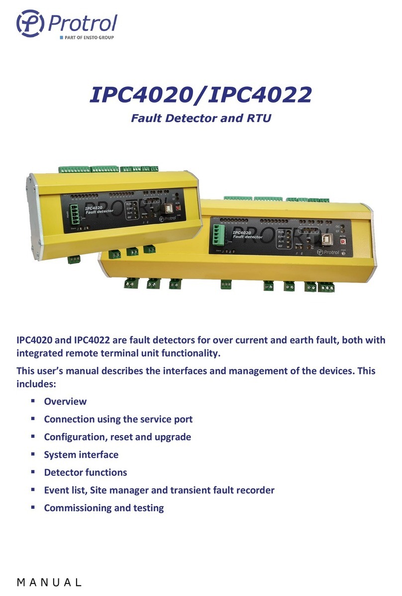
ensto LYNX 4400 User manual

NO. NX2010597/ NO. 72983_C
06/04/2021
1 (35)
Ensto Novexia SAS
210 rue Léon Jouhaux
BP 10446
69656 Villefranche-sur-Saône Cedex,
France
Tel. +33 (0)4 74 65 61 61
Fax +33 (0)4 74 62 96 57
4PR-F14-D
LYNX 4400
Installation and operation manual
for current fault detectors and
directional fault detectors
for MV underground grids

NO. NX2010597/ NO. 72983_C
06/04/2021
2 (35)
4PR-F14-D
General
- Before unpacking
> Verify that the product in its packaging has not been damaged during transport.
> Verify that the product is suitable for the intended installation.
- Before installation
> Carefully read the operation guide before installing or using this product.
> Perform the installation carefully, ensuring that the equipment remains clean throughout the operation.
- After installation
> If you are installing this product for someone else, leave the guide for the end user.
> Clean the work area after installation.
Legal notices
-The product may only be installed by a competent person with adequate training in the installation practices
and with adequate knowledge of proper safety and installation practices for electrical equipment. If local
regulations have requirements relating to this training or adequate knowledge in terms of the installation of
electrical equipment, the aforementioned requirements must be complied with by this person.
-Ensto Novexia declines all liability for any property damage or personal injury caused by poor installation,
mishandling, or failure to comply with safety recommendations.
WARNING
For the operation of this system in complete safety, it is essential that the installers, users and technicians
follow the procedures and precautions described in this guide. Non-compliance with these instructions may
cause damage to the products and/or serious or even fatal injury.
This document is the property of Ensto Novexia. It may not be copied or disclosed to third parties without
written permission. Non-contractual documents, drawings and photos. The information and instructions
provided may change without prior notice.

NO. NX2010597/ NO. 72983_C
06/04/2021
3 (35)
4PR-F14-D
Table of contents
1
Presentation................................................................................................................................................ 4
1.1.
Product purpose.................................................................................................................................. 4
1.2.
General characteristics........................................................................................................................ 4
1.3.
List of equipment required for installation (not supplied by Ensto Novexia)..................................... 4
2
Installation................................................................................................................................................ 10
2.1.
Unpacking and handling instructions................................................................................................ 10
2.2.
Installation operations ...................................................................................................................... 10
2.3.
External connections......................................................................................................................... 10
3
Commissioning.......................................................................................................................................... 17
3.1.
Points to be checked before commissioning .................................................................................... 17
3.2.
List of commissioning operations...................................................................................................... 17
3.3.
Operational tests............................................................................................................................... 17
4
Operation.................................................................................................................................................. 24
4.1.
Function by function description ...................................................................................................... 24
4.2.
Commands, tests, configurations - upgrades with new functions.................................................... 24
5
Maintenance............................................................................................................................................. 29
5.1.
Preventive ......................................................................................................................................... 29
5.2.
Corrective.......................................................................................................................................... 29
6
Technical Assistance................................................................................................................................. 32
7
End of Product Life.................................................................................................................................... 33

NO. NX2010597/ NO. 72983_C
06/04/2021
4 (35)
4PR-F14-D
1
Presentation
1.1.
Product purpose
1.2.
General characteristics
1.3.
List of equipment required for
installation (not supplied by Ensto Novexia)

NO. NX2010597/ NO. 72983_C
06/04/2021
5 (35)
4PR-F14-D
1.1.
Product purpose
LYNX 4400 fault detectors are designed to be installed on the underground sections of MV grids earthed by
means of a limiting resistor or impedance. The detector enables the following aims to be achieved:
•
Improving detection performance
•
Counting faults and changing the operation of auxiliary contacts
•
Standardising cores, PPACS, indicator lights and their connections
•
Standardising and extending the usable lives of batteries and supercapacitors
•
Using plug and coded type connectors for connecting current probes
1.2.
General characteristics
Front panel detail
Error indicator lights Display Calibration indicator light
Test reset and
PPACS calibration button
Display and counter
reset button
Test button
Polycarbonate
case
7 flexible cable
grommets Identification
label

NO. NX2010597/ NO. 72983_C
06/04/2021
6 (35)
4PR-F14-D
Characteristics of LYNX44XX in amperometric configuration
MV grid (in accordance with specification EDF PR-HN-45-S-50 of February 2011)
Voltage Frequency
15 to 20 kV
50 Hz / 60 Hz
Single-phase current thresholds in A
20 - 40 - 80 - 160 - 240
Polyphase current thresholds in A
500, 750, 1200, 1600
Double current thresholds in A
250, 450, 700, 1200
Fault indication duration in Hours
2 hours
Fault response time in ms
100 ms
Fault indication reset after triggering
-Indication locking
-By the return of LV or MV > 5 A
-On expiry of the long-term time delay
-By manual operation
3 s
2 hours
Reset button
Characteristics of LYNX44XX in directional configuration
MV grid (in accordance with specification EDF PR-HN-45-S-51 of February 2011)
Voltage Frequency
15 to 20 kV
50 Hz / 60 Hz
Single-phase phase-earth fault detection
Indication according to the direction of the fault
Red or Green
Thresholds at 20 kV
Preset 1
Preset 2
Residual current
25 A < Ir < 35 A
50 A < Ir < 70 A
Residual voltage
3 kV < Vr < 5 kV
7 kV < Vr < 11 kV
Validation of
detection over 50 ms
1.5 kV < Vr < 2 kV
3 kV < Vr < 4 kV
In 15 kV position, the thresholds are reduced to three quarters of these values
Double phase-earth fault detection
-Trigger threshold
-Fault triggering time delay
-Indication
250 A rms
80 ms
Alternating red-green
Detection of polyphase faults
-Average trigger threshold on balanced fault
-Fault triggering time delay
-Indication
500 A rms
80 ms
Alternating red-green

NO. NX2010597/ NO. 72983_C
06/04/2021
7 (35)
4PR-F14-D
Validation time delay
-From the disappearance of the MV, before triggering of the indicator lamps
(configuration using microswitches)
-From MV presence after MV restoration
10-20-40-70 s
5 s
Fault indication reset after triggering
-By the return of LV or MV > 5 A
-On expiry of the long-term time delay
-By manual operation
3 s or 2 h
Reset button
Common characteristics
Accumulators/Batteries
350-F Lithium supercapacitor
LSH20 batteries
Display
4-digit display
H = 17.8 mm
External indicator light housing
-Number of LEDs
-Total luminous flux
-Flashing frequency
-Standard flashing capacity with lithium batteries
6
7 Ln
1 s
200 h
Environment
-Operating temperature
-Storage temperature
-Humidity level
-Vibration resistance (IEC 68-2-6 & 68-2-29)
-Protection rating
-Overall dimensions
-Device mass (excluding cables)
-15 ° to + 55 °
-25 ° to + 70 °
Up to 100%
2 g (peak value)
IP30 IK07
289 x 200 x 92
1.1 kg

NO. NX2010597/ NO. 72983_C
06/04/2021
8 (35)
4PR-F14-D
Cable routing
External indicator light
Parallel connection
LV power supply Parallel connection of PPACS
LV power supply
Remote indication PPACS voltage
Climatic conditions
Storage
Storage temperature: -25 to +70°C
Relative humidity: 10 to 100%
Operation
Normal operating temperature: -15
to +55°C
200
Cores
289
92.50

NO. NX2010597/ NO. 72983_C
06/04/2021
9 (35)
4PR-F14-D
1.3.
List of equipment required for installation
LADAC detectors:
NAME
Ensto
Novexia no.
DESCRIPTION AND CONTENTS
Lynx 4425
NX2009362
Lynx 3425 low voltage supply+super capa. + cable 7m
Lynx 4425
NX2010140
Lynx 3425 low voltage supply+super capa. 10kV + cable 7m
Composition of a complete unit:
1 Lynx case equipped depending on the version
oWith LV power supply and supercapacitor
oStandalone with two LSH20 batteries
Accessories supplied alone (depending on the option)
1 red and green external indicator light housing connected to the Lynx using a 5, 10, or 15-m
connection cable
1 Lynx connection cable with core connectors 2, 5, 10, or 15-m long
1 Lynx shielded connection cable with PPACS connectors 2, 5, 10, or 15-m long
3 resin-coated cores with 1-metre wired connectors
LSH20 battery
Standard equipment enabling the device to be wall-mounted (screws and wall plugs) is not
supplied by Ensto Novexia.

NO. NX2010597/ NO. 72983_C
06/04/2021
10 (35)
4PR-F14-D
2
Installation
2.1.
Unpacking and handling instructions
2.2.
Installation operations
2.3.
External connections

NO. NX2010597/ NO. 72983_C
06/04/2021
11 (35)
4PR-F14-D
2.1.
Unpacking and handling instructions
Open the box and check in relation to the order.
2.2.
Installation operations
Installing the LYNX 4400 case
The LYNX 4400 case is mounted on a flat wall using the following accessories (not included in the
supply):
4 slotted head screws Ø4.5 X L 35 mm
4 wall plugs Ø6 L 30 mm
To access the 4 case mounting holes, remove the cover.
After inserting the wall plugs in the wall (see
mounting distances opposite), position each of the
four Ø 4.5 screws in its hole.
Installing the external indicator light housing
The indicator light housing is supplied with a 3X1.5² U1000RO2V type cable, 5, 10 or 15 metres long
depending on the order.
Mounting distances for the housing 53 x 38 mm (2 x Ø 4.5 screws).
To connect the indicator light housing to the LYNX case see page 15.
Mounting distances:
215 mm x 175 mm

NO. NX2010597/ NO. 72983_C
06/04/2021
12 (35)
4PR-F14-D
2.3.
External connections
J4 J5 J9 J1 J2
Connecting the CORES (power off)
The current probes used with the LYNX 4400 are split
core current sensors with a lever clasp on a resin-
coated core.
Ratio 1/500.
The assembly uses three identical cores detecting:
-single-phase faults on the earth
-polyphase faults
-double faults
USE OF CORES VERSION 2012
2. Installation

NO. NX2010597/ NO. 72983_C
06/04/2021
13 (35)
4PR-F14-D
Modular MV cell Compact MV cell
Protective shield
Green side
Earth for
cable shields
and the
IP2X connector for the cores cores' S2s
Each core is mounted on a phase of the underground cable, with the green side facing towards the unit's
busbar.
It is centred and attached to the cable using 3 self-centring rubber bosses.
THE SCREENED BRAID FOR EACH PHASE MUST BE CREATED BY AN INSULATED CONDUCTOR AND
PASSED INSIDE THE CORRESPONDING CORE.
The wires for each core are connected using a coded 2-contact MATE-N-LOCK connector.
A 4x1.5mm² U1000RO2V type cable equipped with female MATE-N-LOCK connectors is supplied for
connecting cores to the LYNX 4400's J2 terminal block.
Insert the stripped end with end sleeves into the LYNX's cable grommet.
Connect the J2 terminal block as follows:
l1 l2 l3 C NC
Terminal I1: Brown wire
Terminal I2: Black wire
Terminal I3: Grey wire
Terminal C: Blue wire (common)
NC terminal: Not connected
Green side
Earth for cable
shields and the
cores' S2s
Core IP2X connector

NO. NX2010597/ NO. 72983_C
06/04/2021
14 (35)
4PR-F14-D
Connecting the PPACS VOLTAGE SENSORS (in case of directional detector)
The voltage sensors used with the LYNX 4400 are the capacitive dividers of the separable connectors
(plug-in terminals) located:
-Either on the transformers of the MV/LV stations
-Or on the network cells of the disconnection stations.
These capacitive dividers were previously equipped with removable PPACS voltage connection. See the
installation guide of the PPACS supplier.
An earth connection must also be created.
All of the wiring from the PPACS and from the earth connection must be grouped in a standardised
female Harting socket.
To connect the capacitive dividers to the LYNX 4400, a shielded 4X0.5mm² cable is supplied. This cable is
equipped with a standardised male Harting socket on the capacitive divider side.
Connect the J1 terminal block (removable and screwed in) as follows:
Using the Ensto cable
With Cahors cable
Connection of the Lynx cases in parallel (max. 3 per PPACS):
-Route the end of the cable through the cable grommet provided (refer to page 8)
-Connect to terminal J1 by doubling the wires in the terminal block
Important note! The set-up requires cases of the same type (LYNX 4400). You must always
restart the calibration procedure on all cases (refer to page 22).
Terminal U1: wire No. 1
Terminal U2: wire No. 2
Terminal U3: wire No. 3
Terminal C: wire No. 4
Terminal U1: white wire
Terminal U2: green wire
Terminal U3: red wire
Terminal C: three black wires together

NO. NX2010597/ NO. 72983_C
06/04/2021
15 (35)
4PR-F14-D
Connecting the external indicator light housing
The LYNX 4400's indicator light housing has red and green lights. It is supplied with a 3X1.5mm²
U1000RO2V type cable. Position the indicator light with the cable gland facing downwards.
Connect the J9 terminal block as follows:
Terminal +: Brown wire
Terminal V: Black wire
Terminal R: Grey (or blue) wire
+ V R
Connecting to remote indication
The connection is made using a 4X1.5mm² U1000RO2V type cable - not supplied
An equipment fault may be actuated by the detector in response to:
- A need to replace the battery or batteries when the battery becomes flat after 7.5 years of use
- An anomaly affecting the alternative auxiliary power supply
- An anomaly affecting the electronics
Connect the J5 terminal block (removable and screwed-in) as follows:
Power supplies (depending on the option)
LV power supply + supercapacitor option 350 Farad 2.7 V supercapacitor - Usable life 15 years
Standalone option: 2 x D20 LSH 20 type lithium batteries, not supplied - Usable life: ≥ 7.5 years
Note: the two batteries face in the same direction (+ to the left).
NC NC R V DE C
Terminals NC: Not connected
Terminal R: Red fault
Terminal V: Green fault
Terminal DE: Equipment fault
Terminal C: Common

NO. NX2010597/ NO. 72983_C
06/04/2021
16 (35)
4PR-F14-D
NB: During lengthy storage periods, the lithium battery may be passivated, and therefore unable to
supply the current needed for the LYNX 3400 to operate. To depassivate it:
-Short-circuit its terminals with a 47-ohm 3-W resistor
-Wait for a noticeable rise in the resistor's temperature (10 to 30 seconds depending on the
batteries)
-230-V AC external power supply (LV power supply option)
The LYNX 4400's normal power source is low voltage 230 V, which is available on site. The LV is supplied
to the LYNX 4400 by a 2 x 1.5mm² U1000RO2V type cable –not supplied. LYNX 4400s do not need to be
connected to the neutral earth.
Connecting the J4 connector
Insert the cable via the LYNX 4400's cable grommet.
Connect the cable's neutral and phase wires as follows:
-- Neutral, to the left-hand terminal.
-- Phase, to the right-hand terminal.
Check the condition of fuse F1. A 5X20 F type (250 mA)
spare fuse is available on the lower left-hand side
of the detector.
N PH

NO. NX2010597/ NO. 72983_C
06/04/2021
17 (35)
4PR-F14-D
3
Commissioning
3.1.
Points to be checked before commissioning
3.2.
List of commissioning operations
3.3.
Operational tests

NO. NX2010597/ NO. 72983_C
06/04/2021
18 (35)
4PR-F14-D
3.1.
Points to be checked before commissioning

NO. NX2010597/ NO. 72983_C
06/04/2021
19 (35)
4PR-F14-D
3.2.
List of commissioning operations
Selection of the type of detector: Amperometric or directional (configured as directional on leaving the
factory)
Position the selector
On the DDA side for an overcurrent fault detection configuration
On the DFD side for a directional fault detection configuration
LYNX44XX configured in amperometric fault detection mode
1.
Configuration of the homopolar lo detection threshold (phase to earth)
Ex-factory setting: 80 A
2.
Configuration of the indicator light colour for a homopolar fault
Ex-factory setting: Red homopolar fault
3.
Configuration of polyphase Imax detection thresholds (phase to phase)
Ex-factory setting: 500 A
Rm: The polyphase threshold is always higher than the double threshold.
Switch
240 A
160 A
80 A
40 A
20 A
1
OFF
OFF
ON
OFF
ON
2
OFF
OFF
OFF
ON
ON
3
OFF
ON
ON
ON
ON
Switch
Red homopolar fault
Green homopolar fault
4
OFF
ON
Switch
1600 A
1200 A
750 A
500 A
5
OFF
ON
OFF
ON
6
OFF
OFF
ON
ON

NO. NX2010597/ NO. 72983_C
06/04/2021
20 (35)
4PR-F14-D
4.
Configuration of detection thresholds I Double
Ex-factory setting: 450 A
5.
‘Power on’ condition
Ex-factory setting: Power on via LV restoration or I > 5 A
6.
Indication reset condition configuration
Ex-factory setting: Indication reset by LV restoration
LYNX44XX configured in directional fault detection mode
1.
Selection Preset 1 / Preset 2
LYNX 4400 units have two detection levels, called Preset 1 and Preset 2.
Preset 1 corresponds to the greatest earth fault detection sensitivity. This position is used
preferentially.
The Preset 2 position is intended for special cases, such as when most of the detectors used
for the outputs are older-generation detectors (pre-2009).
Switch
1200 A
700 A
450 A
250 A
1
OFF
ON
OFF
ON
2
OFF
OFF
ON
ON
Switch
Power on via LV restoration
Power on via LV restoration or I = 5 A
3
OFF
ON
Switch
Indication reset by restoration of
power
Indication reset by 2-h time delay
4
OFF
ON
Table of contents
Other ensto Security Sensor manuals
Popular Security Sensor manuals by other brands
Honeywell Home
Honeywell Home PROSiXCT installation instructions

PCB
PCB 4115K-08A Installation and operating manual
Ziton
Ziton ZR432-2P installation guide
RLE Technologies
RLE Technologies Falcon WIFI-LD quick start guide
Ingersoll-Rand
Ingersoll-Rand FALCON 1690 Touchbar installation instructions
C-LOGIC
C-LOGIC 615-MD instruction manual
