Ensy AHU-300 HV User manual
User manual and
Installation Guide
AHU-300 HV
AHU-300 HH

393870-2 Rev0: 11.07.2018 BBV
We reserve the right to change technical data without notice. http://www.ensy.no Page 1

393870-2 Rev 0: 11.07.2018 BBV
We reserve the right to change technical data without notice. http://www.ensy.no Page 2
User manual.Page 1 to 13
(Front page and pictures on pages 1-5 shows AHU-300 HV)
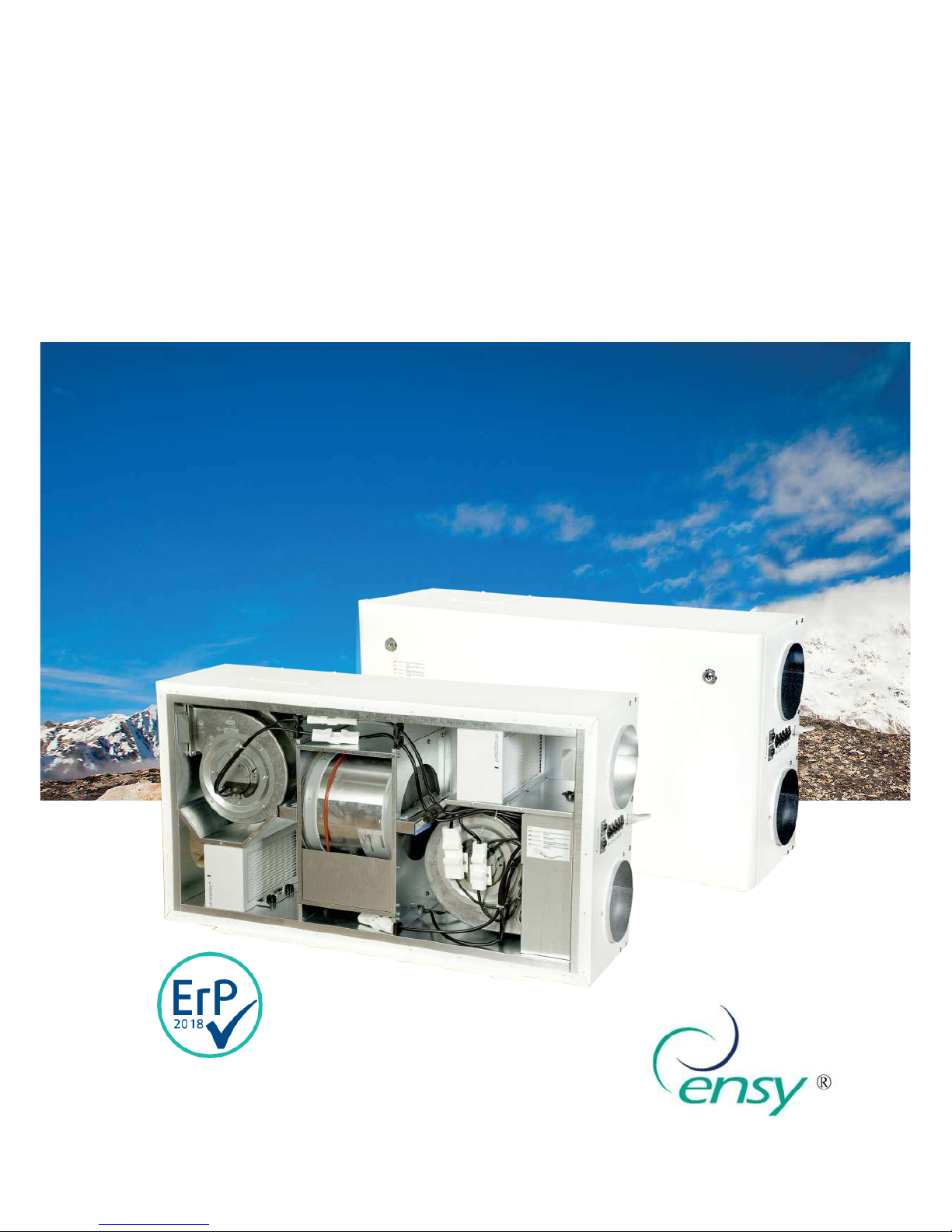
To open the front hatch
you will find a key for the
quarter turn latches in
the folder together with
the following documents.
Keep this key in a place so it is out of reach
for children.
To open the locks, turn the key toward the
center of the unit.
Left latch Right latch
To operate this product
people should have
necessary skills, or under the
supervision of a qualified person.
Children should be told to not play
with the appliance.
Before any access into the electrical connections boxes, power must be
disconnected by pulling out the plug from the socket.
It is only allowed for authorized persons to enter into the electrical connection boxes. (Sketch shows
AHU-300 HH)
If any electrical components are damaged, they must be replaced by the manufacturer, dealer or a
qualified person in order to avoid dangerous situations.

393870-2 Rev 0: 11.07.2018 BBV
We reserve the right to change technical data without notice. http://www.ensy.no Page 3
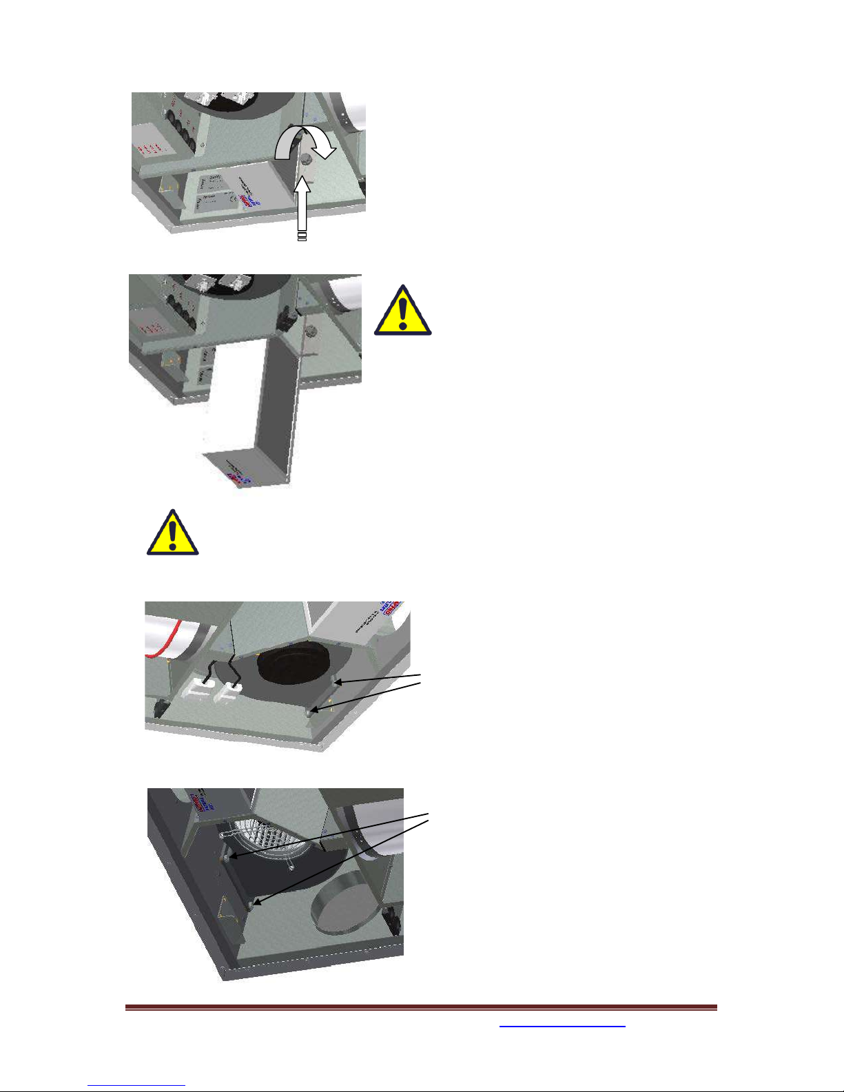
The hatch has three hinger that holds it permanently to the housing. If the unit is placed high under a
ceiling, then is mandatory to get help from another person to take down the hatch. It can be done by
unscrewing 6 pcs of screws from the housing or front hatch.
The safety wire can be removed from inside of the front hatch so that the hatch can be
opened or removed. The safety wire must be reinstalled before the hatch closes.
To close, after putting the hatch back on place, turn the latches the opposite way. You may use some
pressure towards the hatch to close it.

393870-2 Rev 0: 11.07.2018 BBV
We reserve the right to change technical data without notice. http://www.ensy.no Page 4
Adjustment of the unit.
Ahumidity sensor is, from factory, mounted inside the unit. It is set to “0” that
means it is set to not active.
Note!This switch is not used on units produced before february 2015.
After startup, where the unit is placed into a new building with high
humidity, you can let this humidity sensor be turned off for a period
to avoid the full speed of the fan at night. To get the humidity
sensor to operate as intended, you need at one time to put it active.
Than you need to set the switch in position "1".
If the ventilation unit is placed in a house without high humidity,
you should switch to position "1" after you putting ventilation unit
into operation.
This switch will also affect any extra external humidity sensor that is
plugged into the device.
Adjusting the humidity sensor.
If it is necessary to adjust the sensitivity
of the humidity sensor then you just can
remove the black plug and you then can
see the adjusting knob and the RH%
scale.
Note!This black plug is not on
units produced before february
2015.
If bad light condition, it may be easier to
remove the cover so that you easier
seethe RH% scale.
The sensor is set to 80% RH from factory.
If you do adjustments, this only affect
the sensor integated inside the unit.
The sensitivity for the integrated sensor
you can adjusted from 50% (low) to 90%
(high) in accordance to what are the
needs. The arrow points the value
chosen.
If you have a second external sensor that
means you need to adjust that one from
its settings.
Replace the cover and / or plug after
finish adjusting.
393870-2 Rev 0: 11.07.2018 BBV
We reserve the right to change technical data without notice. http://www.ensy.no Page 5
Replacing the filter.
The filters should be replaced every 6. 9. or 12. months.
Before the filters can be removed, you have to unscrew a
little bit two crews for each locking bracket. Push the
bracket away from you to release the filters.
Should than be extracted without use of any tools.
To guarantee optimal properties of the
ventilation unit, use the original filters from
EnSy. The use of spurious filters will limit the
warranty on the product
Ensy art number for filter set is:
011460860-2
FILTERSETT ENSY AHU 300 Himling. F7: 140x240x94.
To insert a new filter you then first have to puch the
bracket away from yourself. Then put the filter in place
and then pull the bracket against yourself and tighten the
skrews on the bracket.
Remember to enter the control panel menu (4.3 Filter) and press Filter OK after the
filters has been replaced.
Cleaning the fans.
This must be done by a qualified person.
Before removing fans the main power must be
disconnected by pulling out the main supply
plug from the socket, or fans to be
programmed to position “AV” or “OFF”
Disconnect the 3-pole and 5-pole plugs.
Before you are able to remove the fans you
first have to unscrew two screws for each fan
that holds the fan in correct position.
The fans can then be pulled out of the
ventilation unit without the need for any tools.
When the fan is placed back into the unit, then
make sure the screws are tightened so that
there is no danger that they loosen during
operation.
Clean with mild soap and water.

393870-2 Rev 0: 11.07.2018 BBV
We reserve the right to change technical data without notice. http://www.ensy.no Page 6
Maintenance and cleaning of rotary heat exchanger
This must be done by a qualified person.
If the unit is placed high under a ceiling, then it might be an advantage to get help from another
person to hold the rotor exchanger in correct position till all four “safety” screws are loosen.
Disconnect the 3-poled plug , and then unscrew those four “safety” screws that holding the rotor
exchanger in place.
(Sketch shows AHU-300 HH, but the
princip is the same for AHU-300 HV)
Can be pulled out of the ventilation
unit without the need for any tools.
Rotor exchanger can easily be removed for
cleaning by unscrewing 12 screws that hold it
together.
Clean parts with mild soap and water.
Do not expose the rotor motor or
connector for moisture.
The exchanger you also can clean
with mild soap and water. Do not use ammonia-
containing detergent, as this will prey on and
discolor aluminum in rotary heat exchanger.
Flushed with hand shower and blow gently clean
with compressed air.
Ensure that all 12 screws are tightened sufficiently so that they do not come loose
during operation.
Preferably use a screwdriver to tight the screws. If use of electrical screwdriver, make
sure that you use low torque to prevent destroying the threads in the sheet metal parts.
To make sure that the drive belt can adjust itself into correct position you must rotate the exchanger
some few turns. Then insert back into the ventilation unit. Be sure that rotor exchanger is properly
inserted in all the guides inside the unit. If not, this can lead to vibration in the system and internal
air leak in the unit. Make sure that all four “safety” screws are tightened so that there is no danger
that they loosen during operation.

393870-2 Rev 0: 11.07.2018 BBV
We reserve the right to change technical data without notice. http://www.ensy.no Page 7
Main menu
1. Control Button indicator for fan.
2.Control Button indicator set point.
3.Control Button indicator information.
4.Control Button indicator settings.
Overview of control panel
The main screen consists of, from top, left:
Time Indication, hour, minute
Timer, Weekly schedule (if programmed)
Reheating coil (if connected)
Temperature readings, Outdoor / Indoor
Status airflow – fan speed setting
OFF MIN NORM or MAX
Temperature set point, 15 - 21 °C
Reheating coil – (here refers active element)
Rotary exchanger Indicator - (here refers
active rotary wheel)
Indicators in the menu screen:
"Sun" indicates that the rotor has
stopped, the air handling unit is in the
summer operation mode.
"Snowflake" low temperature
indicates that the air handling unit is
in defrosting mode.
"Steaming pot" and blinking fan blades
indicates that the kitchen exhaust is
activated.
"Timer" and the countdown of the fan
symbol indicate that the forced
ventilation is enabled.
From 10 up to 240 minutes
"Away" indicates when the feature is
enabled, this feature will override
timer.
"Clock over the fan symbol" indicates
that the timer is activated.
Co2 over the fan symbol" indicates
that the carbon sensor is activated.
"Exclamation point" indicates that
moisture recorded over the sensor is
higher than the set value.
May also indicate that the motion
sensor is activated if connected on D2
signal output.
Control Button 1.
2.
3.
4.

393870-2 Rev 0: 11.07.2018 BBV
We reserve the right to change technical data without notice. http://www.ensy.no Page 8
1.Fan speed
Ventilation unit has three options for choice of
airflow.
Min, Normal and Max.
For programming of values within each step,
see 4.5.1.3 Using the control button 1, and - /
+ buttons can change between the pre-
programmed selections.
1.1 Fan boost
Forced ventilation, fan speed increases to max
speed. (Means to the speed that is set in
menu 4.5.1.3.) The function is for use if high
humidity in bathrooms and laundry room.
Forced ventilation can be activated with
button
then
Interval adjustable from 10 - 240 min with +
and -
This picture shows 10 min forcing time, but
not activated.
To activate the fan boost use
control button 4.
You can see that the fan are running with Max
speed and the clock will start countdown.
You can easy deactivate the fan boost again
before the countdown automatically stops it.
First control buttom 1 and then 4.
This feature can also be operated with an
external pulse switch. The switch is placed in
the bathroom or adjacent rooms. Connected
to contact D1 in top of the ventilation unit.
(Look at page 19 or 20 in this manual.)
If this option via D1 is intended for use against
wood stove or fireplace then it is
recommended that Max speed under Fan
control in menu 4.5.1.3. is set to Supply 100%
and adjust Extract to be 80 to 85%. (Look at
page 10 in this manual)
2. Temperature
Choose from pre-programmed temperature
settings set point between 15 - 21 °C. Setting
is changed by operating the switch buttons
below - / +symbols.
Heating element can here be set ON or OFF
by operating the switch button 4 in this
screen, but only if heater is connected.
(To see if heating coil is connected or
disconnected, see 4.5.1.1 Heater)
Indicator for activated heating coil.
Small picture show not activated.
393870-2 Rev 0: 11.07.2018 BBV
We reserve the right to change technical data without notice. http://www.ensy.no Page 9
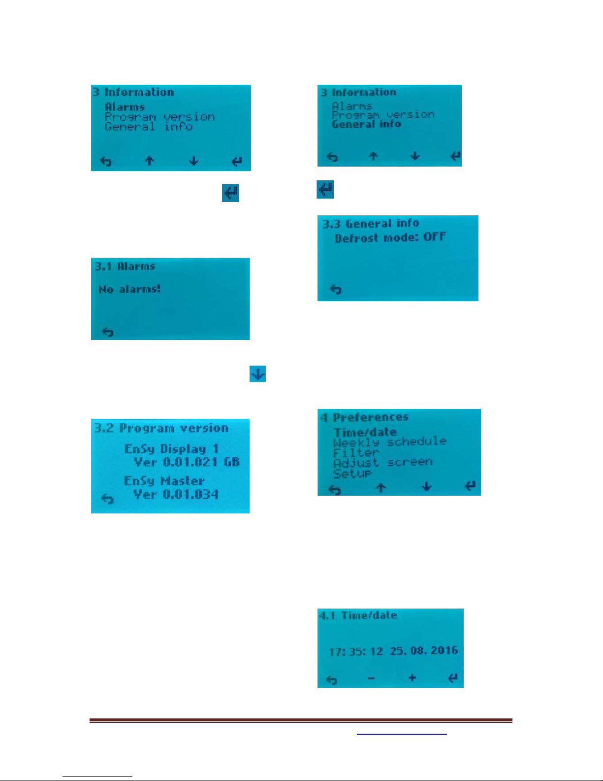
3. Information.
3. Information / 3.1.Alarms
When alarm you can find a source of error
here, as well as info on how the alarm is reset.
(See pages 29 and 30 in this manual)
3. Information / 3.2 Program version
Information about the software
version. This information must be provided to
service personnel at the failure of the unit.
Which display is defined as Display 1 or
Display 2 appears here if the plant has
mounted two displays.
See 4.5.1.10 selection of the displays.
3. Information / 3.3. General info
Here you can see defrost mode that has
been chosen.
(See 4.5.1.9 if you want to change mode.)
4. Preferences
To navigate within the various sub-menus
when using the control buttons below the up /
down cursor key that displays on the display.
4. Preferences / 4.1 Time/date
Setting menu for Time/date. This setting is
important since the information forming the
basis for the weekly schedule function if this is
to be activated. Also for the filter alarm
function it is needed.
393870-2 Rev 0: 11.07.2018 BBV
We reserve the right to change technical data without notice. http://www.ensy.no Page 10
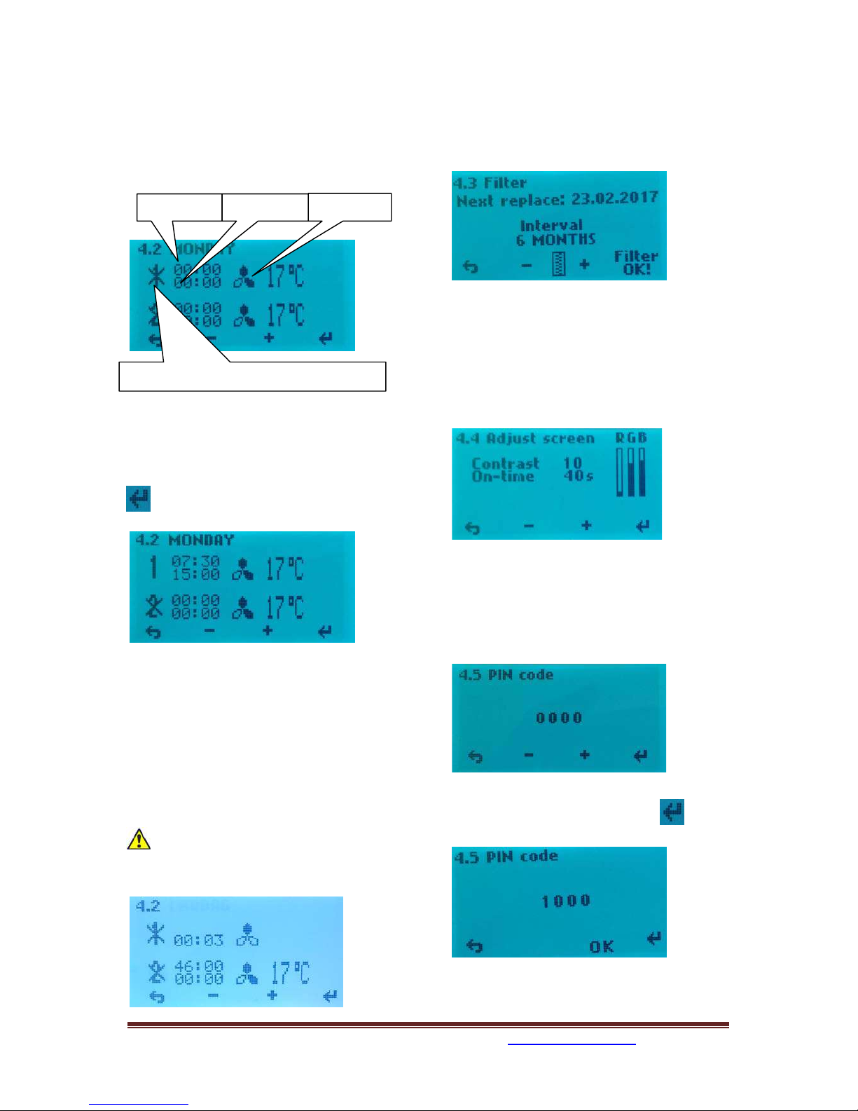
4. Preferences / 4.2 Weekly schedule
Programming of the Weekly schedule, fan
speed and temperature set point. Here it can
be programmed for two periods each day. Ex.
day - night.
Every day must be programmed individually.
Monday - a period of time, select the start
time. To activate the period, X - over period
number is removed, use the -/ +keys.
Use enter to move between the different
fields.
Choose airflow (fan speed) Speed dialing -
MIN when one fan blade on the indicator is
black. NORM = two black fan blades on the
indicator. MAX speed = three black fan blades
on the indicator.
Select the desired supply air temperature you
want during the period. Settings between 15 -
21°C.
If weekly schedule looks something like
this without any reason then you must
punch in all the data again.
It do not help to update software.
4.Preferences / 4.3 Filter
Setting the time interval for filter change,
current choices are 6, 9 or 12 months. Make
your choices by using the cursor keys +/ -.
Alarm reset elapsed period by pressing the
menu button 4, under "Filter OK"
4. Preferences / 4.4 Adjust Screen
Adjusting the contrast and color on the
display.
You can also adjust how long it should be light
in the display after the operation.
4. Preferences / 4.5 Setup
To proceed, use PIN code 1000
Press +once till it shows 1000 in
display. Then press 4 times on
Then press button 3 for OK 4.5.1
Start time
Stop time
Fan speed
Activation of the period. Here not active
393870-2 Rev 0: 11.07.2018 BBV
We reserve the right to change technical data without notice. http://www.ensy.no Page 11
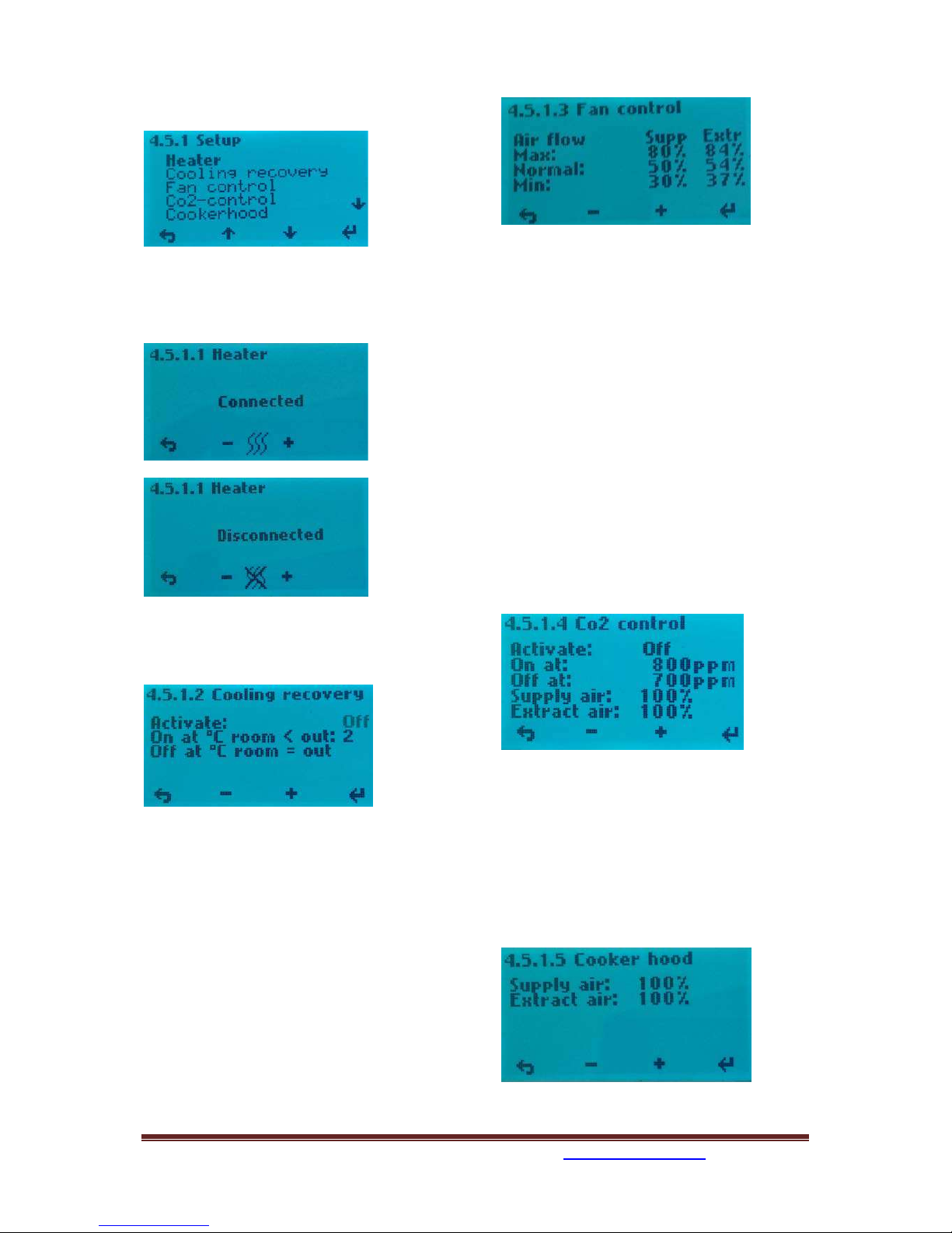
4.5.1 Setup
4.5.1.1 Heater
Turning on/off the reheating coil, use the
minus or plus button to change settings.
4.5.1.2 Cooling recovery
Activation of the cooling recovery:
It is pre-programmed two options for use
when the outside temperature is higher than
the indoor temperature, heat recovery system
will activate the function start and supply air
will be cooled by exhaust air. Engagement
when the outdoor temperature is 2 °C or 3 °C
higher than room temperature. Use button 4
to change setting for Off. Press +to activate
(On). Use button 4 to change setting for 2°C.
Press +to change to to 3°C, if wanted.
4.5.1.3 Fan control
Factory settings for AHU-300 HV and HH you
can see in next picture.
The installer can adjust these settings so that
it is adequately balanced ventilation.
4.5.1.4 Co2 control
If the unit shall be connected CO² control then
connect it to C0² connector on top of the unit.
(See page 19 or 20 in this manual).
Menu for enabling / disabling of CO² control.
Scroll to Off and press +to activate. On
Here you preprogrammed wanted ppm value
and the boost speed for the fans.
Note: To get balanced ventilation is a
prerequisite that Supply and Extract air fan
has the same value as the MAX value under
4.5.1.3
4.5.1.5 Cooker hood
Menu for programming of fan speeds by
activation of the kitchen hood. KV connector
on the top of the unit (see page 19 or 20 in
this manual) should always get signal from the
kitchen hood when this is activated. This to
prevent rotor alarm.
393870-2 Rev 0: 11.07.2018 BBV
We reserve the right to change technical data without notice. http://www.ensy.no Page 12
Supply and Extract air should have the same
value as the MAX value under 4.5.1.3 (Set to
100% from factory.)
Even if it is installed an "active" kitchen
ventilator with piping not connected towards
the unit, the KV plug must get the signal to
see that kitchen ventilator is activated. This
can be done by using a a pressure switch in
the exhaust tube from the ventilator. Then
Extract set down to around 50% or less to
compensate for the extract air in the hood.
Note! If KV signal plug is not in use for
cooker hood then you can use the signal to get
more supply air when to fire up a fireplace.
Then adjust so that supply air delivers more
air than extract air fan. In this case you must
use a switch and not impulse switch.
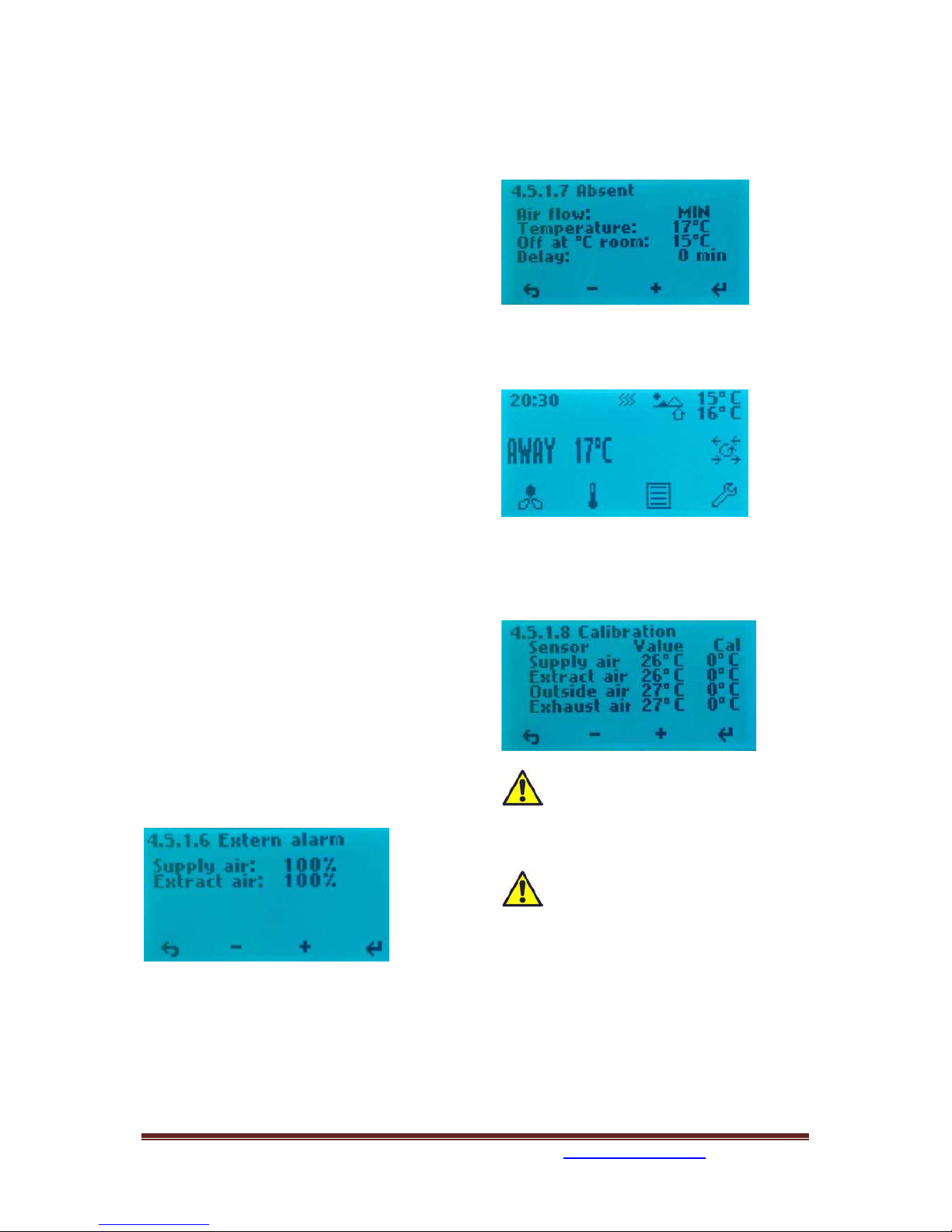
4.5.1.6 Extern alarm
If the unit has been connected to an external
humidity sensor or motion sensor. Use the D2
connector on top of the unit. (See page 19 or
20 in this manual). Note! In order for this
feature to work, you need the one-pole switch
marked RH% ON / OFF inside the unit to be set
in position 1. (See page 3 in this manual for
the location of this switch).
Supply and Extract air should have the same
value as the MAX value under 4.5.1.3 (Set to
100% from factory.)
4.5.1.7 Absent
Menu for setting the desired values by
activating away / home function.
Use the D3 connector on top of the unit. (See
page 19 or 20 in this manual) Function is
operated via an external switch.
Set value of the desired temperature will
show in the display after activating the
function.
4.5.1.8 Calibration
Menu reading of embedded temperature
sensors.
These temperature sensors are
delivered calibrated from the
manufacturer and should not be attempted
change in here.
The «Outside air» sensor normally
shows 3-6°C highter temperaature
then the reel outside temperature. This is due
to heating of the air in the duct network from
the intake grille to the intake of the unit
where the sensor are placed.

393870-2 Rev 0: 11.07.2018 BBV
We reserve the right to change technical data without notice. http://www.ensy.no Page 13
4.5.1.9 Defrost
Menu for how to change defrost mode if
temperature is low and humidity is height.
From the start up menu you can see which
defrost mode the unit is set in.
The unit is set in mode OFF from factory.
If it is needed to change the defrost
mode to another mode then press
button 4 and scroll down to Configuration
with button 3.
Press enter button and follow procedure
as in Menu 4.5 Setup to continue.
Press enter button
Defrost mode OFF from factory.
Modus 1: at low humidity.
Defrosting function start at -20°C.
Modus 2: at normal humidity.
Defrosting function start at -15°C.
Modus 3: at high humidity.
Defrosting function start at -10°C.
The function when defrosting starts is that
each hour the supply air fan stops for 6
minutes. The heater EV turns off. Extract air
fan reduces speed to 30% and the rotary
exchanger will run as normal.
To avoid that the rotary exchanger will stop
when the cycle goes back to normal function,
the supply air fan will start up the last minute
of the defrosting mode cycle.
(Supply air fan reacts delayed relative to the
control signals and rotary exchanger so that
the heater will not engage until the speed of
the supply air fan has passed 250 r/min, in
normal operation).

393870-2 Rev 0: 11.07.2018 BBV
We reserve the right to change technical data without notice. http://www.ensy.no Page 14
4.5.1.10 Display number
If two control panels should be used, then
from this menu it has to be specified that one
of the control panels is «Display 1» and the
other one is «Display 2». This to avoid delay in
the signals between the control panels and
main control board inside the unit.
It does not matter which of the control panels
that are called Display 1 or Display 2.

We reserve the right to change technical data without notice. http://www.ensy.no Page 15
393870-2 Rev 0: 11.07.2018 BBV
Mounting instructions. Page 14 to
30.
1.General
2. Mounting of the unit
2.1 Brackets and gaskets to avoid vibration
2.2 Alternative placement on wall
2.3 Placement under concrete ceiling
3. Connections
3.1 Electrical connections
3.2 Duct connections
4.Setting the airflow
5. Alarms
1.General
This guide is made to provide installation and user instructions regarding the correct installation of AHU-
300 HV and HH.
AHU-300 HV and HH is designed for heat recovery with air volumes of up to 220 m³ / h. The energy from
the exhaust air is transferred to supply air through the rotary heat exchanger where the air streams pass
each other without making contact.
The unit has a built in-heater for supplementary heating of supply air.
Humidity sensor for forced ventilation is integrated into ventilation unit.
For AHU-300 HV and HH the control panel is not integrated in the unit. It is delivered separate together
with the unit, are supplied with 10 meters cable, and plug to fit the socket outside the unit.”STYREPANEL”
Option for a second control panel to be connected is also made outside the unit. “STYREPANEL” (See page
19 and 20)
The unit can also connect additional equipment cooker hood over the stove, pulse switch for controlling
the forced ventilation, for example, wet rooms or bathrooms, sensor for carbon management and switch
management away / home function. Control of these options are integrated into AHU-300 HV and HH.
AHU 300 HV and HH is supplied in painted finish, tested and ready for operation.
Installation, commissioning and tuning must be performed by authorized personnel.
2. Mounting
Together with the unit is delivered the following equipment:
1. Suspension bracket
2. Bracket with vibration dampening gasket for ceiling montage
3. Self-adhesive vibration damping
4. Accessories bag containing the necessary screws
5. 5 pcs. plugs for connecting additional equipment.
6. Key for opening the front hatch.
7. Control panel with 10 meters cable
We reserve the right to change technical data without notice. http://www.ensy.no Page 16
Exhaust air
Fresh air from outside
Supply air to room
Cooker hood
Extract air from room
393870-2 Rev 0: 11.07.2018 BBV
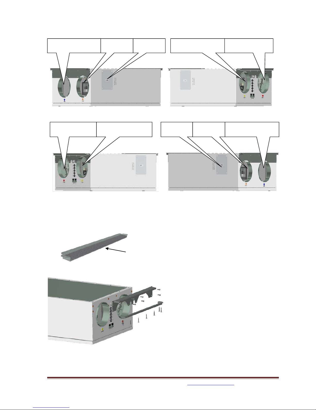
First, select how the unit should bemounted sothat the piping system should beaseasy aspossible
(Sketch shows AHU-300 HH)
(Sketch shows AHU-300 HV)
2.1 Brackets and vibration gasket
Make sure that the gasket is placed on both brackets.
Supply air to room
Exhaust air
Cooker hood
Extract air from room
Fresh air from outside
393870-2 Rev 0: 11.07.2018 BBV
We reserve the right to change technical data without notice. http://www.ensy.no Page 17
Suspension brackets screwed on the unit as shown on both
ends of the unit.
Use 8 pcs M5 x 16mm, supplied with the unit.
Attach one of the ceiling brackets in correct
position in the roof.
Use 7 pcs wood screws 5 x 40mm, supplied with
the unit, for each bracket
Then lift the unit and place the bracket on the
unit between the gasket and roof.
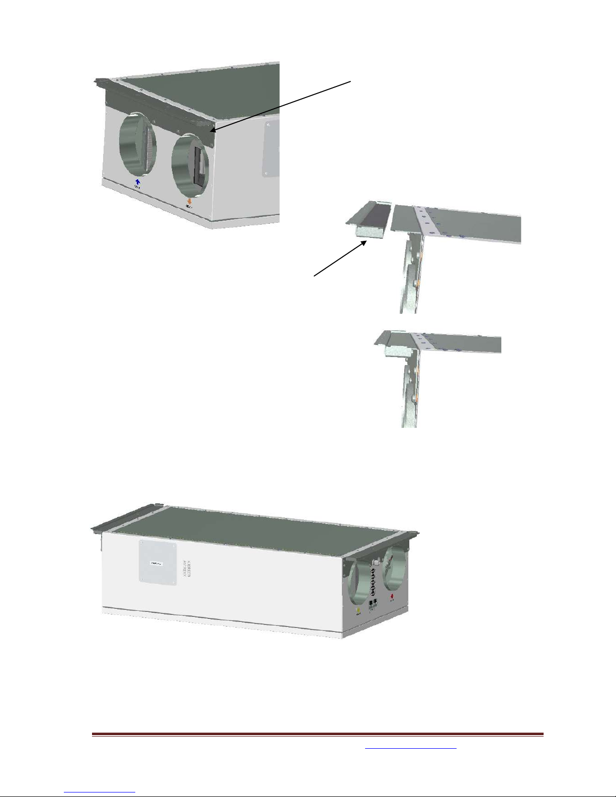
Then lift up the unit in correct position and make sure there are no contact between parts on unit and
building construction.
Then the second bracket
can be placed in the other
end of the unit.

393870-2 Rev 0: 11.07.2018 BBV
We reserve the right to change technical data without notice. http://www.ensy.no Page 18
2.2 Alternative placement on wall
The unit can also be placed on a wall. You then need the use of a separate wall bracket. This do not follow
the unit and has to be ordered separate. (Ensy Art no: 01008045-2)
To avoid vibration from the unit towards building constructions it here is important that there are placed
5 mm vibration damper on the back of the unit.
Two vibration gaskets screws for the extra
bracket follows the extra bracket.
One of the gaskets are placed in top of the
unit.
The other one you place approx. 60 mm
from the button of the unit so that id do not
will come in contact with the wall bracket.
Then first put those two brackets in each end of the unit as
shown on page 16.
Then the wall brackets, with 10 mm gasket, is screwed to the
wall where it is wanted.
Use 8 pcs wood screws 5 x 40mm.
Then you can lift the unit and place it on the wall bracket. Then you use the brackets that follows the unit.
One in each end. Use 7 pcs wood screws 5 x 40mm, supplied with the unit, for each bracket
Wall bracket
393870-2 Rev 0: 11.07.2018 BBV
We reserve the right to change technical data without notice. http://www.ensy.no Page 19
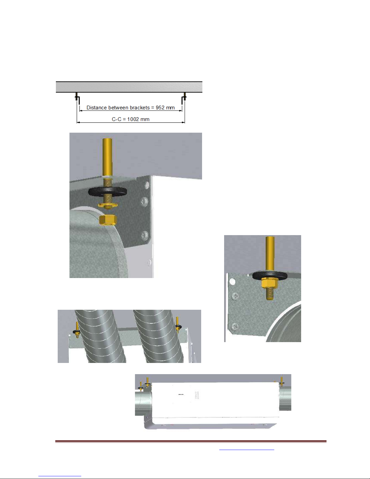
2.3 Placement under concrete ceiling
If the unit is to be mounted directly into concrete ceiling where there may be uneven or not level than it
may be easiest to use expansion bolts fastened into the ceiling. That way, you can adjust with the nuts so
that the unit is in level.
If so, then use the suspension brackets as jigs
for the bolts so that the distance between
brackets will be correct.
Use correct drill for use for the M10 mm
expansion bolts.
Make sure the bolt is turned so hard that it
can not loosen. The bolts are available in
different lengths so select someone suitable
for this purpose. Lift the unit into position.
Use a rubber cushioning, 4-6 mm thick,
between washers and mounting brackets.
Then adjust with the nuts so that the unit is in
level.
This manual suits for next models
1
Table of contents
Other Ensy Fan manuals


