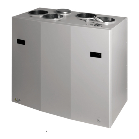
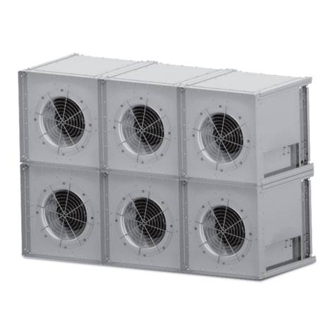
Ensy InoVent AHU-200 Series User manual

User manual and
Installation Guide
InoVent AHU-200-700

393930-2 Rev 0: 01.04.2020
2 | Page

393930-2 Rev 0: 01.04.2020
3 | Page
1
Read this first!
The contents of this manual are subject to change without notice.
ENSY® holds the copyright to this user’s manual. The user shall follow any instructions given in this user
manual entirely and not only partly. Any non-following of this user manual result in exclusion of all
warranties, guarantees, and liabilities.
Copyright© 2020 by ENSY® AS. All Rights Reserved.
Disposing of the parts of the controller:
INFORMATION FOR USERS ON THE CORRECT HANDLING OF WASTE ELECTRICAL AND ELECTRONIC
EQUIPMENT (WEEE)
Disposal must be in accordance with European Union directives and the related national legislation.
1.1 Reading instructions
The following symbols are used to draw the reader’s attention to different warning levels.
Important information
Danger!! General danger
Danger!! High voltage! Danger of electrical current or voltage
1.2 User manual
Before installation the user should be thoroughly familiarized with this user manual, especially with
purposes, installation, settings and operation.
Special care should be taken when installing and connecting external equipment (sensor, high voltage
etc.) and handling the PCB’s correctly according to protection against ESD
Installation of the electronics/parts must be performed by authorized personnel only. All
warranties are excluded in case installation is performed by unauthorized personnel or in
case the spare parts have not been correctly installed.

393930-2 Rev 0: 01.04.2020
4 | Page
2
Functions of the Air Handling Unit C o n tr o l le r
The Air Handling Unit controller is designed for domestic and smaller industrial ventilation systems. Heat
recovery can be either passive or active using a heat pump. Air heater can be added to either pre-heat or
after-heating the inlet air.
The air handling unit can also be extended with hot tap water production using a heat pump taking energy
from the exhaust air.
Depending on the complexity and size of the ventilation system the following functionality is available:
•Ventilation control
•Temperature control
•Heat recovery – via rotor heat exchanger
•Air heater – after-heater
•Defrosting
•User functions
•Week program
•External heat source control
•Filter monitoring via pressure-drop measurement (optional)
2.1 Ventilation control
2.1.1
Start-up
Unit with outputs for air dampers can be configured for a delayed start of the ventilation fans. This gives the air
dampers time to be fully opened before pressure builds up. Via a menu the ventilation start delay can be
adjusted. Inlet starts another 1 minute after the exhaust fan has started.
If low winter ventilation is activated, the unit will always start up at the selected winter low step the first 2
minutes.
2.1.2
Ventilation based on humidity and CO2 level
A humidity sensor (included) and a CO2 level sensor (optional) can be connected to the unit controller. The
controller will adjust ventilation based on the desired settings in the Air quality menu.
The installer configures the humidity levels where ventilation should change speed either up or down.
NOTE! REMOVE THE DUST CAP FROM THE SENSOR AFTER THE UNIT WAS INSTALLED!!!
In the same menu the settings for ensuring a comfortable CO2 level can be configured. There are two CO2 levels,
a normal level and a high level where the ventilation speed will be increased.
Both sensors have 3 minutes settling time after start from ventilation step Off. Average = 24 hours average. RH
(high) = Average + 10%; RH (low) = average + 3%
2.2 Temperature control
2.2.1
Low room temperature alarm
This function ensures the room temperature is not getting too cold. If the room temperature is getting below
the room low-temperature limit, the inlet speed is reduced 1 step. After 5 minutes the speed is reduced
again until temperature can be maintained.
If the room temperature cannot be maintained, the fans are stopped, and a Low Room Temp warning is set.
An external room temperature sensor is mounted.
The function can be disabled by setting the Room low limit to off in the Room control menu.
2.2.2
Summer/Winter operation
The controller can automatically switch between summer and winter operation based on the outdoor
temperature. After each shift, the unit stays here for 15 min before another shift is allowed.
The difference between summer/winter operations is the minimum temperature of the inlet air and that the
bypass damper is normally not opened in wintertime.
2.2.3
Control sensor
The controller can use different controlling sensors. Supply: The inlet temperature sensor is used; there is no
room temperature control. Extract: The extract temperature sensor is used.

393930-2 Rev 0: 01.04.2020
5 | Page
2.3 Air heater (after-heater)
The air heater (or after heater) heats up the air after the air has passed the heat exchanger. It must be enabled
and configured in the Air heater menu.
The heater can be None or Electrical.
The electrical heater has a 0 – 10V analogue output and the heater relay is turned on when the heater is
needed.
2.4 Defrosting
Defrosting is done for 6 minutes every hour. During defrost, the supply fan is stopped, the exhaust fan is
running at MIN speed, the air heater is off and rotor speed is normal.
•Mode 1 is for low humidity and starts at -20⁰C
•Mode 2 is for normal humidity and starts at -15⁰C
•Mode 3 is for high humidity and starts at -10⁰C
After defrosting, the air heater is first started when fans are up and running
2.5 User selection functions
Activating the User function digital input can trigger different functions.
The air handling unit will perform this operation during the selected period and overriding the other user
settings including week program settings.
Function
Duration
Supply air
level
Exhaust fan
level
None
No action
-
-
Fan boost
Input active
MAX
MAX
Supply air (increase
supply air)
15 min – 8h
Off, MIN, NORM,
MAX
NORM
Extract air (increase
extract air)
15 min – 8h
NORM
Off, MIN,
NORM, MAX
Extern alarm
15 min – 8h
Off, MIN, NORM, MAX
2.6 Cooker hood function
There is a separate digital input for the operation together with a turned-on cooker hood extractor.
Function
Duration
Supply air
level
Exhaust fan level
None
No action
-
-
Cooker hood
Input active
0-100%
0-100%
2.7Rotor control
The rotor heat exchanger is always started some minutes before the heater. This ensures the rotor is first
started when the rotor alone is insufficient.
2.8 Party mode
The user can activate a party mode. It is used for increased ventilation with many people in the ventilated
area. Fan speed is set to MAX, the user can set it to MIN or NORM afterwards.
The existing set point is used. The user can change the set point during active party mode.
Party mode is automatically stopped when the party timeout period is over. Default timeout is 4 hours, it can
be changed after the activation. Party timeout menu is hidden when party mode is off.
2.9 Away mode
The away mode is for periods with low ventilation needs like away on holiday etc.
At activation, fan speed is set to MIN and set point to 15°C. Both fan speed and set point can be changed
afterwards. The Away mode must be turned off manually.
Fan speed and set point returns to the settings when the away mode was started.

393930-2 Rev 0: 01.04.2020
6 | Page
3. Menu system
3.1 Overview of the menu system
Pressing the menu button will open several screens and menus. Press to
go back to previous menu.
Press and buttons to scroll up and down in the menus
If the alarm icon, is visible, pressing it will open the alarm menu
Password
Password
Factory settings
Main menu
Unit on/off
Fan speed
User selection
Set Point
Alarm
Unit Information Week program
Settings Main screen
Readings Service settings
Date/time
Screen set.
Language
User
10⁰C...26⁰
Alar
Unit
Week
Air
Normal /
Reading
Servic
Date/tim
Factor
Screen
English / German /
French
/ Danish /
Norwegian
/ Polish
/ l / h /

393930-2 Rev 0: 01.04.2020
7 | Page
3.2 Main menu
The main screen is the default menu. The display returns to this
screen after some minutes without user interaction.
It shows the actual temperature, measured relative humidity and
actual fan speed.
A week program and an alarm are active on this example pressing
the button or the temperature will open the temperature set
point menu
Show the measured humidity
The fan speed can be adjusted by pressing the button or the
speed
The user can select if the main menu should show a house
Touch the inlet arrow to set the desired temperature
3.3 Possible icons in the menu headline
Press the menu button to access the sub-menus
A week-program is active
One or more alarms are active
The air handling unit is turned off
Wi-Fi connection is not connected

393930-2 Rev 0: 01.04.2020
8 | Page
4. User settings menu
This is the user level of the menu system
Show run-mode
Touch to start and stop of the unit, On / Off
Show fan speed.
Touch to adjust fan speed; Off, MIN, NORM, MAX
Sub-menu with setup for different user configurable inputs
Turn Party mode on/off.
Increased fan speed for many people
Range: Off, On; default Off
Time out of Party mode. Only visible if Party mode is On.
Range 1 – 24 hours; default 4 hours
Turn Away mode on/off.
Reduced fan speed, MIN and lower set point 15°C
Range On, Off; default off
Show actual set point
Touch to adjust set point; range 10⁰C – 26⁰C
List, number of active alarms.
Open the alarm sub menu if there is an active alarm Sub-
menu with software versions for the unit

393930-2 Rev 0: 01.04.2020
9 | Page
Sub-menu with more user-settings
Sub-menu with temperatures and other operation data
Show and adjust date and time in a sub-menu
Adjust backlight levels in active and idle mode
Adjust display language.
Select between English, German, French, Danish, Norwegian, Polish, Italian,
Dutch and Lithuanian
Week program sub-menu. Lists if a program is active
Switch between normal main menu and house main menu
Sub-menu with service settings. Password protected. Password is 5
Sub-menu with service settings. Password protected. Password is 50

393930-2 Rev 0: 01.04.2020
10 | Page
,
,
4.1 User selection sub-menu
The unit has a digital input which can trigger a user- configurable function, i.
e. an increased fan speed when guests are coming. The input overrides the
normal operation
Select program: None, Fan boost, Supply air, Extract air, Extern alarm. Default
None
Menu only visible if a duration after activation can be set. Else function is
active when digital input is active.
Range Off: Until input is released; 15 min to 8 hours Menu visible for some
programs.
Set the fan speed to use when digital input is active
Range Off, MIN, NORM, MAX
4.2 Alarm handling menus
Sub-menu with warnings and critical alarms for the air handling unit.
Critical alarms will stop the unit. The unit may continue operation with a
warning.
If the alarm icon is red it is a critical alarm and the air handling unit will
stop.
Touch to open a more detailed description
If the alarm icon is yellow it is a warning and the air handling unit may
continue to operate
Touch to open a more detailed description
If the alarm icon is grey, , it is an inactive warning or critical alarm. The
alarm may have to be acknowledged to start the unit again.
Touch to open a more detailed description
Detailed description of a warning or critical alarm
Date/time the alarm came active
Touch Clear alarm to clear the alarm. If the alarm number starts with small
letters, c/w, the alarm can be cleared Alarm number, severity and description
Trouble shooting information for the alarm/warning

393930-2 Rev 0: 01.04.2020
11 | Page
List the software versions in the controller and display of the air handling
unit
Controller software version
Display software version
MAC address of the Wi-Fi radio
4.3 Settings for the air handling unit
Sub-menu for configuration of the cooker hood function. The air handling
unit will help push the steam towards the cooker hood
Set the temperature were the air handling unit switches to summer mode
Range 5⁰C.. 30⁰C; default 17⁰C
Set the minimum air inlet temperature in summer mode Range 5⁰C.. 50⁰C;
default 10⁰C
Set the minimum air inlet temperature in winter mode
Range 5⁰C .. 50⁰C; default 15⁰C
Set the maximum air inlet temperature in summer mode
Range 5⁰C .. 50⁰C; default 30⁰C
Set the maximum air inlet temperature in winter mode
Range 5⁰C .. 50⁰C; default 40⁰C

393930-2 Rev 0: 01.04.2020
12 | Page
Sub-menu for cooling recovery
Maximum rotor exchange speed Range 0% . 100%; default 100%
4.3.1 Cooker hood function
The air handling unit has a digital input for the cooker hood.
When the signal is active, the Supply and Extract fan speeds are
set to the specified speeds in 0-100%
Duration of the fan speeds after signal has disappeared. Range 00:00 (only
run when active signal);
1 min .. 1 hour 30 min; default 0 min
Supply fan speed during active cooker hood signal Range 0 – 100%; default
100%
Extract fan speed during active cooker hood signal Range 0 – 100%; default
100%
4.3.2 Cooling recovery function
Cooling recovery is used when the intake air temperature is
higher than the room temperature to keep the rooms cool.
Turn the cooling recovery mode On or Off Default
Off
Activate cooling recovery when the intake air temperature is
2⁰C or 3⁰C higher than the room temperature.
Range 2⁰C or 3⁰C

393930-2 Rev 0: 01.04.2020
13 | Page
4.4 Readings sub-menu
The menus contain readings for the sensors and outputs
Measured relative humidity
Supply air temperature
Extract air temperature
Air temperature at the air heater
Fresh air temperature
Exhaust air temperature (after the rotor heat exchanger)
Supply fan speed in percentage
Extract fan speed in percentage
Air heater percentage

393930-2 Rev 0: 01.04.2020
14 | Page
Speed of rotor heat exchanger
Pressure difference over the inlet air filter Used for filter clogging monitoring
(optional)
4.5 Date/time sub-menu
The controller has a built-in real time clock used for alarm
logging
Set the year
Set the month
Set the day of month
Set the hour (24h)
Set the minutes

393930-2 Rev 0: 01.04.2020
15 | Page
4.6 Screen settings
Set the backlight level when the display is active – being used
Set the backlight level in idle mode
Calibrate the touch panel only if the display responds unaligned
with finger touches!
Please note it must be done carefully as the display may else
become impossible to use!
4.7 Week program
The week program is used to program different fan speeds in up to 6 periods
per day and 3 different week programs, i. e. a normal week, holiday, a week
with shift-working hours
Select program 1, 2 or 3
Sub menu with program 1, 2 or 3 to edit
Reset selected program 1, 2, or 3 to default factory settings.
The user will get a warning before applying the reset
Touch Program 1 to edit program 1 in sub-menus
Touch Program 2 to edit program 2 in sub-menus
Touch Program 3 to edit program 3 in sub-menus

393930-2 Rev 0: 01.04.2020
16 | Page
Every weekday can have its own 6 different profiles, typically
weekends are different
Touch to edit settings for Monday
Touch to edit settings for Tuesday
Touch to edit settings for Wednesday
Touch to edit settings for Thursday
Touch to edit settings for Friday
Touch to edit settings for Saturday
Touch to edit settings for Sunday

393930-2 Rev 0: 01.04.2020
17 | Page
Every function or profile has its own 3 settings: Start time, set point and fan
speed. When start time is reached, the set point is set to the entered value
and fan speed to the setting
Overview of function 1 on Monday
Touch to edit this function / profile
Overview of function 2 on Monday
Touch to edit this function / profile
Overview of function 3 on Monday
Touch to edit this function / profile
Overview of function 4 on Monday
Touch to edit this function / profile
Overview of function 5 on Monday
Touch to edit this function / profile Off
means the function is not active
Overview of function 6 on Monday
Touch to edit this function / profile Off
means the function is not active
Touch to copy all 6 functions setting for the day, here Monday,
to the next day. Used if the next day should have the same
settings

393930-2 Rev 0: 01.04.2020
18 | Page
Every function / profile of the day has its own settings
Start time of the profile in 15 minutes interval
Range 00:15 to 23:45. 00:00 equals Off and means no function
Fan speed
Range Off, MIN, NORM, MAX
Level is hidden if Start time is Off
Desired temperature. Overwrites the main menu setting
Range 10°C to 26°C
Temperature is hidden if Start time is Off
Reset a program to default settings
Touch to reset program 1
Touch to reset program 2
Touch to reset program 3
Security question if you want to reset all settings in the
program to default values

393930-2 Rev 0: 01.04.2020
19 | Page
Select if the main screen should be the house or the normal
view with lines
Accept or cancel
4.8 Service settings
Service settings are for the service technician and are password protected.
The default service password is 5
Accept change with or decline with
Sub-menu with air handling settings
Sub-menu with calibration option of temperature sensors
Different counters for the air handling unit

393930-2 Rev 0: 01.04.2020
20 | Page
Sub-menu with air flow filter monitoring via pressure
measurement
Sub-menu to start a software update of the controller and
display in the air handling unit
Sub-menu with Wi-Fi settings
Sub-menu with different handling in case of smoke See below
Configure action if the smoke input becomes active. Range: Full stop, Boost
and Stop Supply fan Default Full stop
Accept change with or decline with
This manual suits for next models
10
Table of contents
Other Ensy Fan manuals
Popular Fan manuals by other brands

elsner elektronik
elsner elektronik WL800 Technical specifications and installation instructions
miseno
miseno COOP MFAN-LP8081L manual
RenewAire
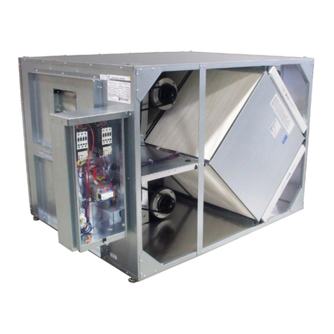
RenewAire HE ERV Series Installation, operation and maintenance manual
Honeywell Home
Honeywell Home Royal Palm user guide

LU-VE
LU-VE ALFA ptigo PF27MC instruction manual
Omega Altise
Omega Altise OT102TW instruction manual
