Ensy AHU-400 BV User manual

User manual and
Installation Guide
AHU-400 BV
AHU-400 BH

393805‐2Rev0:05.05.2017.KJK
Wereservetherighttochangetechnicaldatawithoutnotice.http://www.ensy.noPage1
Usermanual.Page1to13
(Picturesonpages1‐5showsAHU‐400BV)
Toopenthefronthatchyouwillfindakeyfor
thequarterturnlatchesinthefoldertogether
withthefollowingdocuments.Keepthiskey
inaplacesoitisoutofreachforchildren.
Toopenthelocks,turnthe
keytowardthecenterofthe
unit.
Leftlatch Rightlatch
Toclose,afterputtingthehatchbackonplace,turnthelatchestheoppositeway.Youmayusesome
pressuretowardsthehatchtocloseit.
Becarefulthatthedoorcan"bestuck"inthesealingonthehatch.
Foreasierlooseningofthehatch,releaseitfirstinonecorneratthetop.
Tooperatethisproductpeopleshouldhavenecessaryskills,orunderthesupervisionof
aqualifiedperson.
Childrenshouldbetoldtonotplaywiththeappliance.
Whenyouliftoffthefronthatchfromthe
device,makesurethespiralcablethat
connectsthedeviceandthefronthatchisnot
overstretchingforalongperiod.Thiscan
damagethecable
Duringcommisioningoftheappliance,
wheninstalled,thespiralcablehasto
connectedinordertohaveaccessthe
controlpanelinfrontofthehatch.
Whenservicingandcleaning,this
spiralcableshouldbedisconnected.
Makesurethatthespiralcableisdisconnected
andconnectedwithouttheuseofforce.Thisto
preventcontactsoncabletobedamaged.
Ifthespiralcableisoutofposition,thenyouwillgetanalarmcalled"Lowvoltage".Togetthesignal
backintothedisplayyoumustunplugandplugbackinbothhatchandventilationunit.Note!Ifthe
spiralcableisbroken,youhavetoorderneworiginalcablefromsupplier.Standardcablefromstore
wouldnotwork.
Newspiralcablehasart.no:330541‐2fromsupplier.

393805‐2Rev0:05.05.2017.KJK
Wereservetherighttochangetechnicaldatawithoutnotice.http://www.ensy.noPage2
Beforeanyaccessintotheelectrical
connectionsboxes,powermustbe
disconnectedbypullingouttheplug
fromthesocket.
Itisonlyallowedfor
authorizedpersonsto
enterintotheelectrical
connectionboxes.
Ifanyelectricalcomponentsare
damaged,theymustbereplacedbythe
manufacturer,dealeroraqualified
personinordertoavoiddangerous
situations..
Adjustmentoftheunit.
Ahumiditysensoris,fromfactory,mountedinsidetheunit.Itis
setto“0”thatmeansitissettonotactive.
Afterstartup,wheretheunitisplacedintoanewbuildingwithhighhumidity,
youcanletthishumiditysensorbeturnedoffforaperiodtoavoidthefullspeed
ofthefanatnight.Togetthehumiditysensortooperateasintended,youneed
atonetimetoputitactive.Thanyouneedtosettheswitchinposition"1".
Iftheventilationunitisplacedinahousewithouthighhumidity,youshould
switchtoposition"1"afteryouputtingventilationunitintooperation.
Thisswitchwillalsoaffectanyextraexternalhumiditysensorthatis
pluggedintothedevice.
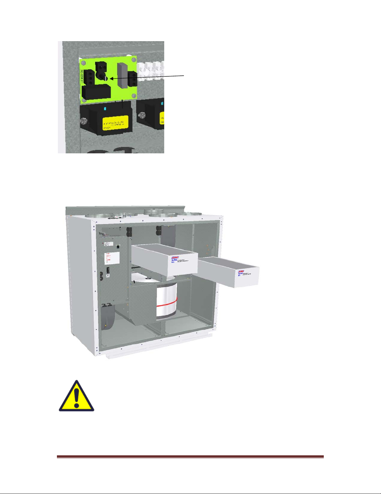
Adjustingthehumiditysensor.
Ifitisnecessarytoadjustthesensitivityofthehumiditysensorthenyou
must,onoldermodels,removethecover,whichisover
thecontrolboardwherethisadjustmentislocated.
Unplugthesupplybeforeremovingthe
cover.
Onnewermodels,youjustcanremovetheblackplug
andyouthencanseetheadjustingknobandtheRH%
scale.
PicturesshowsAHU‐400‐BV
393805‐2Rev0:05.05.2017.KJK
Wereservetherighttochangetechnicaldatawithoutnotice.http://www.ensy.noPage3
Thesensorissetto80%RHfromfactory.
Ifyoudoadjustments,thisonlyaffectthesensor
integatedinsidetheunit.
Thesensitivityfortheintegratedsensoryoucanadjusted
from50%(low)to90%(high)inaccordancetowhatare
theneeds.Thearrowpointsthevaluechosen.
Ifyouhaveasecondexternalsensorthatmeansyouneed
toadjustthatonefromitssettings.
Replacethecoverand/orplugafterfinishadjusting.
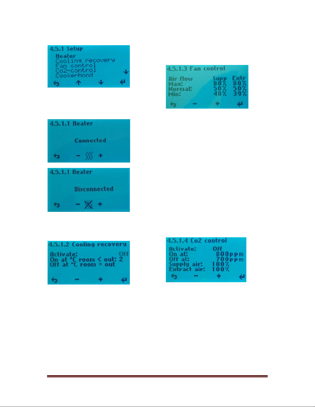
Replacingthefilter.
Thefiltersshouldbe
replacedevery6.9.
or12.months.
Shouldbeextracted
withoutuseofany
tools..
Remembertoenter
thecontrolpanel
menu(4.3Filter)
andpressFilterOK
afterthefiltershas
beenreplaced.
Toguaranteeoptimalpropertiesoftheventilationunit,usetheoriginalfiltersfrom
EnSy.Theuseofspuriousfilterswilllimitthewarrantyontheproduct.
Ensyartnumberforfiltersetis:
011460862‐2
SETFILTREENSYAHU350BV/BH+400_BL/BR_BV/BH.F7:165x370x94

393805‐2Rev0:05.05.2017.KJK
Wereservetherighttochangetechnicaldatawithoutnotice.http://www.ensy.noPage4
Cleaningthefans.
AHU‐400BV
Aqualifiedpersonmustdothis.
Disconnectthe3‐poleand5‐pole
plugs.
Beforeyoucanpulloutthefans,
youhavetoremovethebrackets
thatholdsthefansincorrect
position.
Importantthatthese
bracketsisplaced
backaftercleaning.
Cleanwithmildsoapandwater.
AHU‐400BH
Aqualifiedpersonmustdothis.
Disconnectthe3‐poleand5‐
poleplugs.
Thesupplyairfancanbepulled
outoftheventilationunit
withouttheneedforanytools.
Beforeyoucanpulloutthe
extraxtairfan,youhaveto
removethebracketthatholds
thefanincorrectposition.
Importantthatthis
bracketisplaced
backaftercleaning
Cleanwithmildsoapandwater

393805‐2Rev0:05.05.2017.KJK
Wereservetherighttochangetechnicaldatawithoutnotice.http://www.ensy.noPage5
Maintenanceandcleaningofrotaryheatexchanger
Thismustbedonebyaqualified
person.
Disconnectthe3‐poleplug.
Canbepulledoutofthe
ventilationunitwithouttheneed
foranytools.
Rotorexchangercaneasilybe
removedforcleaningbydissolving
the14screwsthatholdittogether.
Cleanpartswithmildsoapand
water.
Donotexposetherotor
motororconnectorfor
moisture.
Theexchangeryoualsocanclean
withmildsoapandwater.Donot
useammonia‐containingdetergent,
asthiswillpreyonanddiscolor
aluminuminrotaryheatexchanger.
Flushedwithhandshowerandblow
gentlycleanwithcompressedair.
Ensurethatthescrews
aretightenedsufficiently
sothattheydonotcome
looseduringoperation.
Preferablyuseascrewdriverto
tightthescrews.Ifuseofelectrical
screwdriver,makesurethatyou
uselowtorquetoprevent
destroyingthespringsinthesheet
metalparts.
Tomakesurethatthedrivebeltcan
adjustitselfintocorrectposition
youmustrotatetheexchanger
somefewturns.
Theninsertbackintotheventilationunit.Besurethatrotorexchangerisproperlyinsertedinallthe
guidesinsidetheunit.Ifnot,thiscanleadtovibrationinthesystemandinternalairleakintheunit.

393805‐2Rev0:05.05.2017.KJK
Wereservetherighttochangetechnicaldatawithoutnotice.http://www.ensy.noPage6
Mainmenu
1.ControlButtonindicatorforfan.
2.ControlButtonindicatorsetpoint.
3.ControlButtonindicatorinformation.
4.ControlButtonindicatorsettings.
Overviewofcontrolpanel
Themainscreenconsistsof,fromtop,left:
TimeIndication,hour,minute
Timer,Weeklyschedule(ifprogrammed)
Reheatingcoil(ifconnected)
Temperaturereadings,Outdoor/Indoor
Statusairflow–fanspeedsetting
OFFMINNORMorMAX
Temperaturesetpoint,15‐21°C
Reheatingcoil–(hererefersactiveelement)
RotaryexchangerIndicator‐(hererefers
activerotarywheel)
Indicatorsinthemenuscreen:
"Sun"indicatesthattherotorhas
stopped,theairhandlingunitisin
thesummeroperationmode.
"Snowflake"lowtemperature
indicatesthattheairhandlingunit
isindefrostingmode.
"Steamingpot"andblinkingfan
bladesindicatesthatthekitchen
exhaustisactivated.
"Timer"andthecountdownofthe
fansymbolindicatethattheforced
ventilationisenabled.
From10upto240minutes
"Away"indicateswhenthefeature
isenabled,thisfeaturewilloverride
timer.
"Clockoverthefansymbol"
indicatesthatthetimerisactivated.
Co2overthefansymbol"indicates
thatthecarbonsensorisactivated.
"Exclamationpoint"indicatesthat
moisturerecordedoverthesensor
ishigherthanthesetvalue.
Mayalsoindicatethatthemotion
sensorisactivatedifconnectedon
D2signaloutput.
Thissymbolindicatesthatthe
rotaryheatexchangerisactivated
andwillberotated
ControlButton1.2.3. 4.

393805‐2Rev0:05.05.2017.KJK
Wereservetherighttochangetechnicaldatawithoutnotice.http://www.ensy.noPage7
1.Fanspeed
Ventilationunithasthreeoptionsforchoiceof
airflow.
Min,NormalandMax.
Forprogrammingofvalueswithineachstep,
see4.5.1.3Usingthecontrolbutton1,and‐/
+buttonscanchangebetweenthepre‐
programmedselections.
1.1Fanboost
Forcedventilation,fanspeedincreasestomax
speed.(Meanstothespeedthatissetin
menu4.5.1.3.)Thefunctionisforuseifhigh
humidityinbathroomsandlaundryroom.
Forcedventilationcanbeactivatedwith
button
then
Intervaladjustablefrom10‐240minwith+
and‐
Thispictureshows10minforcingtime,but
notactivated.
Toactivatethefanboostuse
controlbutton4.
YoucanseethatthefanarerunningwithMax
speedandtheclockwillstartcountdown.
Youcaneasydeactivatethefanboostagain
beforethecountdownautomaticallystopsit.
Firstcontrolbuttom1 andthen4.
Thisfeaturecanalsobeoperatedwithan
externalpulseswitch.Theswitchisplacedin
thebathroomoradjacentrooms.Connected
tocontactD1intopoftheventilationunit.
(Lookatpage23inthismanual.)
IfthisoptionviaD1isintendedforuseagainst
woodstoveorfireplacethenitis
recommendedthatMaxspeedunderFan
controlinmenu4.5.1.3.issettoSupply100%
andadjustExtracttobe80to85%.(Lookat
page10inthismanual)
2.Temperature
Choosefrompre‐programmedtemperature
settingssetpointbetween15‐21°C.Setting
ischangedbyoperatingtheswitchbuttons
below‐/+symbols.
HeatingelementcanherebesetONorOFF
byoperatingtheswitchbutton4inthis
screen,butonlyifheaterisconnected.
(Toseeifheatingcoilisconnectedor
disconnected,see4.5.1.1Heater)
Indicatorforactivatedheatingcoil.
Smallpictureshownotactivated.

393805‐2Rev0:05.05.2017.KJK
Wereservetherighttochangetechnicaldatawithoutnotice.http://www.ensy.noPage8
3.Information.
3.Information/3.1.Alarms
Whenalarmyoucanfindasourceoferror
here,aswellasinfoonhowthealarmisreset.
(Seepages28and29inthismanual)
3.Information/3.2Programversion
Informationaboutthesoftware
version.Thisinformationmustbeprovidedto
servicepersonnelatthefailureoftheunit.
WhichdisplayisdefinedasDisplay1or
Display2appearshereiftheplanthas
mountedtwodisplays.
See4.5.1.10selectionofthedisplays.
3.Information/3.3.Generalinfo
Hereyoucanseedefrostmodethathas
beenchosen.
(See4.5.1.9ifyouwanttochangemode.)
4.Preferences
Tonavigatewithinthevarioussub‐menus
whenusingthecontrolbuttonsbelowtheup/
downcursorkeythatdisplaysonthedisplay.
4.Preferences/4.1Time/date
SettingmenuforTime/date.Thissettingis
importantsincetheinformationformingthe
basisfortheweeklyschedulefunctionifthisis
tobeactivated.Alsoforthefilteralarm
functionitisneeded.

393805‐2Rev0:05.05.2017.KJK
Wereservetherighttochangetechnicaldatawithoutnotice.http://www.ensy.noPage9
4.Preferences/4.2Weeklyschedule
ProgrammingoftheWeeklyschedule,fan
speedandtemperaturesetpoint.Hereitcan
beprogrammedfortwoperiodseachday.Ex.
day‐night.
Everydaymustbeprogrammedindividually.
Monday‐aperiodoftime,selectthestart
time.Toactivatetheperiod,X‐overperiod
numberisremoved,usethe‐/+keys.
Useentertomovebetweenthedifferent
fields.
Chooseairflow(fanspeed)Speeddialing‐
MINwhenonefanbladeontheindicatoris
black.NORM=twoblackfanbladesonthe
indicator.MAXspeed=threeblackfanblades
ontheindicator.
Selectthedesiredsupplyairtemperatureyou
wantduringtheperiod.Settingsbetween15‐
21°C.
Ifweeklyschedulelookssomethinglike
thiswithoutanyreasonthenyoumust
punchinallthedataagain.
Itdonothelptoupdatesoftware.
4.Preferences/4.3Filter
Settingthetimeintervalforfilterchange,
currentchoicesare6,9or12months.Make
yourchoicesbyusingthecursorkeys+/‐.
Alarmresetelapsedperiodbypressingthe
menubutton4,under"FilterOK"
4.Preferences/4.4AdjustScreen
Adjustingthecontrastandcoloronthe
display.
Youcanalsoadjusthowlongitshouldbelight
inthedisplayaftertheoperation.
4.Preferences/4.5Setup
Toproceed,usePINcode1000
Press+oncetillitshows1000in
display.Thenpress4timeson
Thenpressbutton3forOK..
StarttimeStoptimeFanspeed
Activationoftheperiod.Herenotactive
393805‐2Rev0:05.05.2017.KJK
Wereservetherighttochangetechnicaldatawithoutnotice.http://www.ensy.noPage10
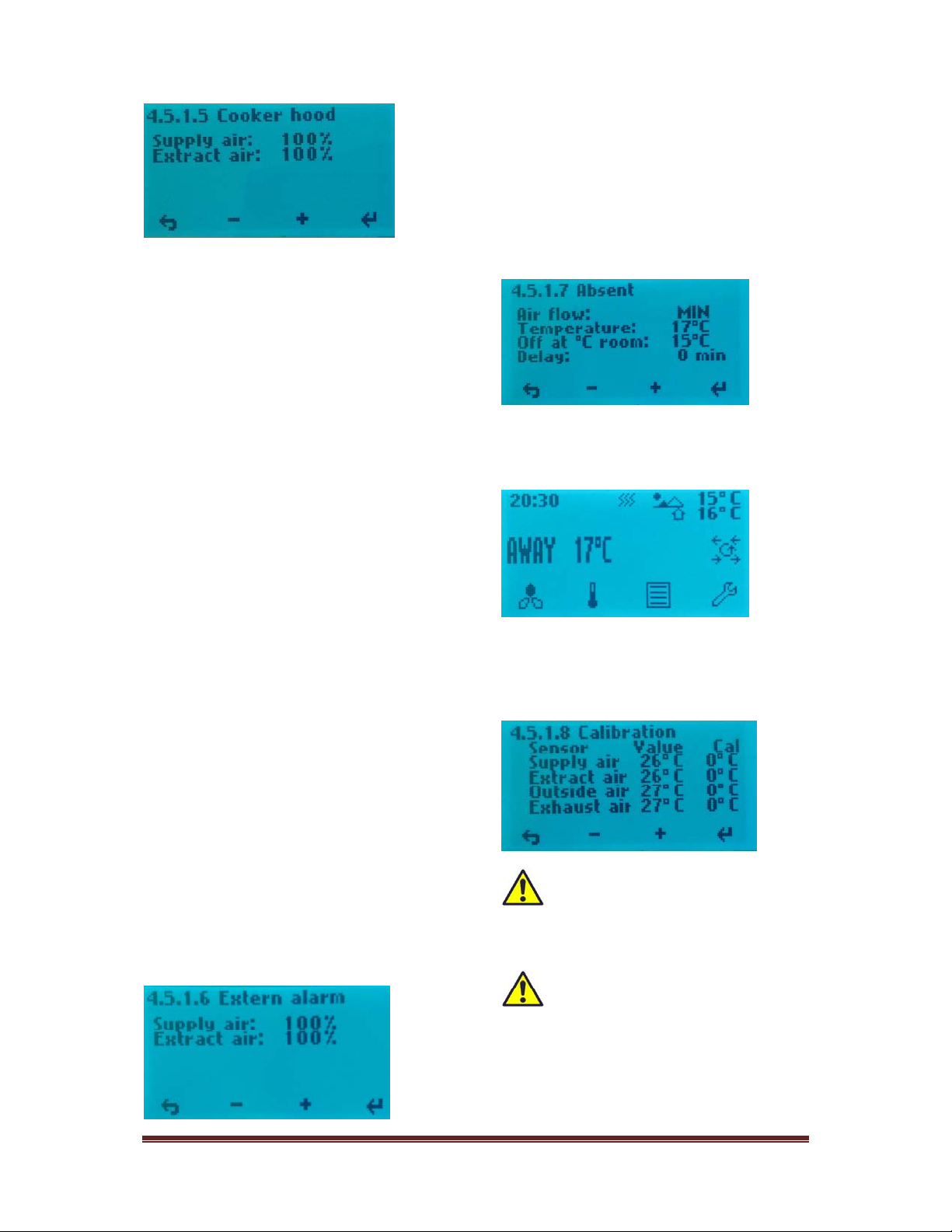
4.5.1Setup
4.5.1.1Heater
Turningon/offthereheatingcoil,usethe
minusorplusbuttontochangesettings.
4.5.1.2Coolingrecovery
Activationofthecoolingrecovery:
Itispre‐programmedtwooptionsforuse
whentheoutsidetemperatureishigherthan
theindoortemperature,heatrecoverysystem
willactivatethefunctionstartandsupplyair
willbecooledbyexhaustair.Engagement
whentheoutdoortemperatureis2°Cor3°C
higherthanroomtemperature.Usebutton4
tochangesettingforOff.Press+toactivate
(On).Usebutton4tochangesettingfor2°C.
Press+tochangetoto3°C,ifwanted.
4.5.1.3Fancontrol
FactorysettingsforAHU‐400BVandBHyou
canseeinnextpicture.
Theinstallercanadjustthesesettingssothat
itisadequatelybalancedventilation.
4.5.1.4Co2control
IftheunitshallbeconnectedCO²controlthen
connectittoC0²connectorontopoftheunit.
(Seepage23inthismanual).
Menuforenabling/disablingofCO²control.
ScrolltoOffandpress+toactivate.On
Hereyoupreprogrammedwantedppmvalue
andtheboostspeedforthefans.
Note:Togetbalancedventilationisa
prerequisitethatSupplyandExtractairfan
hasthesamevalueastheMAXvalueunder
4.5.1.3
4.5.1.5Cookerhood
Menuforprogrammingoffanspeedsby
activationofthekitchenhood.KVconnector
onthetopoftheunit(seepage23inthis
manual)shouldalwaysgetsignalfromthe
kitchenhoodwhenthisisactivated.Thisto
preventrotoralarm.
393805‐2Rev0:05.05.2017.KJK
Wereservetherighttochangetechnicaldatawithoutnotice.http://www.ensy.noPage11
SupplyandExtractairshouldhavethesame
valueastheMAXvalueunder4.5.1.3(Setto
100%fromfactory.)
Evenifitisinstalledan"active"kitchen
ventilatorwithpipingnotconnectedtowards
theunit,theKVplugmustgetthesignalto
seethatkitchenventilatorisactivated.This
canbedonebyusingaapressureswitchin
theexhausttubefromtheventilator.Then
Extractsetdowntoaround50%orlessto
compensatefortheextractairinthehood.
Note!IfKVsignalplugisnotinusefor
cookerhoodthenyoucanusethesignaltoget
moresupplyairwhentofireupafireplace.
Thenadjustsothatsupplyairdeliversmore
airthanextractairfan.Inthiscaseyoumust
useaswitchandnotimpulseswitch.
4.5.1.6Externalarm
Iftheunithasbeenconnectedtoanexternal
humiditysensorormotionsensor.UsetheD2
connectorontopoftheunit.(Seepage23in
thismanual).Note!Inorderforthisfeatureto
work,youneedtheone‐poleswitchmarked
RH%ON/OFFinsidetheunittobesetin
position1.(Seepage2ofthismanualforthe
locationofthisswitch).
SupplyandExtractairshouldhavethesame
valueastheMAXvalueunder4.5.1.3(Setto
100%fromfactory.)
4.5.1.7Absent
Menuforsettingthedesiredvaluesby
activatingaway/homefunction.
UsetheD3connectorontopoftheunit.(See
page23inthismanual)Functionisoperated
viaanexternalswitch.
Setvalueofthedesiredtemperaturewill
showinthedisplayafteractivatingthe
function.
4.5.1.8Calibration
Menureadingofembeddedtemperature
sensors.
Thesetemperaturesensorsare
deliveredcalibratedfromthe
manufacturerandshouldnotbeattempted
changeinhere.
The«Outsideair»sensornormally
shows3‐6°Chightertemperaature
thenthereeloutsidetemperature.Thisisdue
toheatingoftheairintheductnetworkfrom
theintakegrilletotheintakeoftheunit
wherethesensorareplaced

393805‐2Rev0:05.05.2017.KJK
Wereservetherighttochangetechnicaldatawithoutnotice.http://www.ensy.noPage12
4.5.1.9Defrost
Menuforhowtochangedefrostmodeif
temperatureislowandhumidityisheight.
Fromthestartupmenuyoucanseewhich
defrostmodetheunitissetin.
TheunitissetinmodeOFFfromfactory.
Ifitisneededtochangethedefrost
modetoanothermodethenpress
button4andscrolldowntoConfiguration
withbutton3.
Pressenterbuttonandfollowprocedure
asinMenu4.5Setuptocontinue.
Pressenterbutton
DefrostmodeOFFfromfactory.
Modus1:atlowhumidity.
Defrostingfunctionstartat‐20°C.
Modus2:atnormalhumidity.
Defrostingfunctionstartat‐15°C.
Modus3:athighhumidity.
Defrostingfunctionstartat‐10°C.
Thefunctionwhendefrostingstartsisthat
eachhourthesupplyairfanstopsfor6
minutes.TheheaterEVturnsoff.Extractair
fanreducesspeedto30%andtherotary
exchangerwillrunasnormal.
Toavoidthattherotaryexchangerwillstop
whenthecyclegoesbacktonormalfunction,
thesupplyairfanwillstartupthelastminute
ofthedefrostingmodecycle.
(Supplyairfanreactsdelayedrelativetothe
controlsignalsandrotaryexchangersothat
theheaterwillnotengage untilthespeedof
thesupplyairfanhaspassed250r/min,in
normaloperation).
393805‐2Rev0:05.05.2017.KJK
Wereservetherighttochangetechnicaldatawithoutnotice.http://www.ensy.noPage13
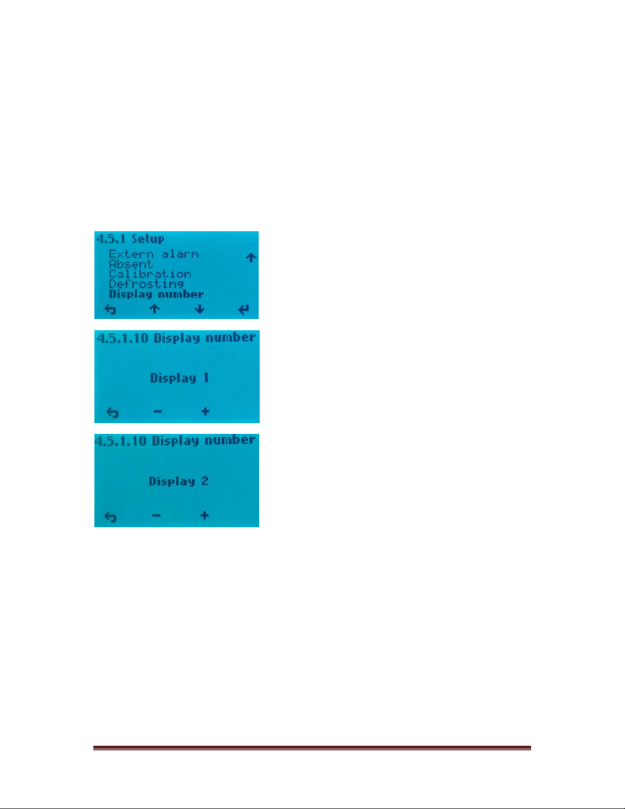
4.5.1.10Displaynumber
Iftwocontrolpanelsshouldbeused,then
fromthismenuithastobespecifiedthatone
ofthecontrolpanelsis«Display1»andthe
otheroneis«Display2».Thistoavoiddelayin
thesignalsbetweenthecontrolpanelsand
maincontrolboardinsidetheunit.
Itdoesnotmatterwhichofthecontrolpanels
thatarecalledDisplay1orDisplay2.

393805‐2Rev0:05.05.2017.KJK
Wereservetherighttochangetechnicaldatawithoutnotice.http://www.ensy.noPage14
Mountinginstructions.Page14to27.
Tableofcontents:
1.General
2.Mountingoftheunit
2.1Bracketsandgasketstoavoidvibration
2.2Stopperbrackets
2.3Mountingofcookerhood
2.4Ductcover
2.5Dimensionsandtechnicaldata
3.Connections
3.1Electricalconnections
3.2Ductconnections
4.Settingtheairflow
5.Alarms
1.General
Thisguideismadetoprovideinstallationanduserinstructionsregardingthecorrectinstallationof
AHU400‐BVandBH.
AHU‐400BVandBHisdesignedforheatrecoverywithairvolumesofupto400m³/h.Theenergy
fromtheexhaustairistransferredtosupplyairthroughtherotaryheatexchangerwheretheair
streamspasseachotherwithoutmakingcontact.
Theunithasabuiltin‐heaterforsupplementaryheatingofsupplyair.Humiditysensorforforced
ventilationisintegratedintoventilationunit.Controlpanelisintegratedintothefronthatch.Option
forasecondcontrolpaneltobeconnectedismadeoutsidetheunit.
Theunitcanalsoconnectadditionalequipmentcookerhoodoverthestove,pulseswitchfor
controllingtheforcedventilation,forexample,wetroomsorbathrooms,sensorforcarbon
managementandswitchmanagementaway/homefunction.Controloftheseoptionsareintegrated
intoAHU‐400BVandBH.
AHU400‐BVandBHissuppliedinpaintedfinish,testedandreadyforoperation.Installation,
commissioningandtuningmustbeperformedbyauthorizedpersonnel.
2.Mounting
Togetherwiththeunitisdeliveredthefollowingequipment:
1.Suspensionbracketandstoppers
2.WallBracketwithvibrationdampeninggasket
3.Self‐adhesivevibrationdamping
4.Accessoriesbagcontainingthenecessaryscrews
5.5pcs.plugsforconnectingadditionalequipment.
6.Keyforopeningthefronthatch.
393805‐2Rev0:05.05.2017.KJK
Wereservetherighttochangetechnicaldatawithoutnotice.http://www.ensy.noPage15
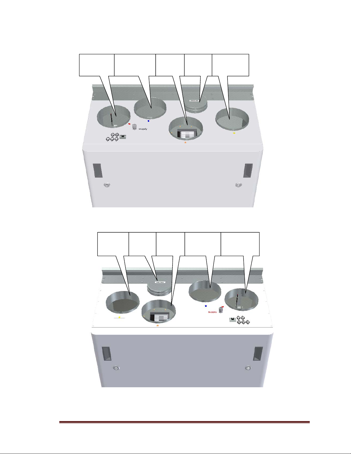
First,selecthowtheunitshouldbemountedsothatthepipingsystemshouldbeaseasyaspossible.
(SketchovershowAHU‐400BV)
(SketchovershowAHU‐400BH)
Cooker
hood
Exhaust
air
Extractair
fromroom
Supplyairto
room
Freshair
fromoutside
Cooker
hood
Freshairfrom
outside
Supplyair
toroom
Extractair
from room
Exhaust
air
393805‐2Rev0:05.05.2017.KJK
Wereservetherighttochangetechnicaldatawithoutnotice.http://www.ensy.noPage16
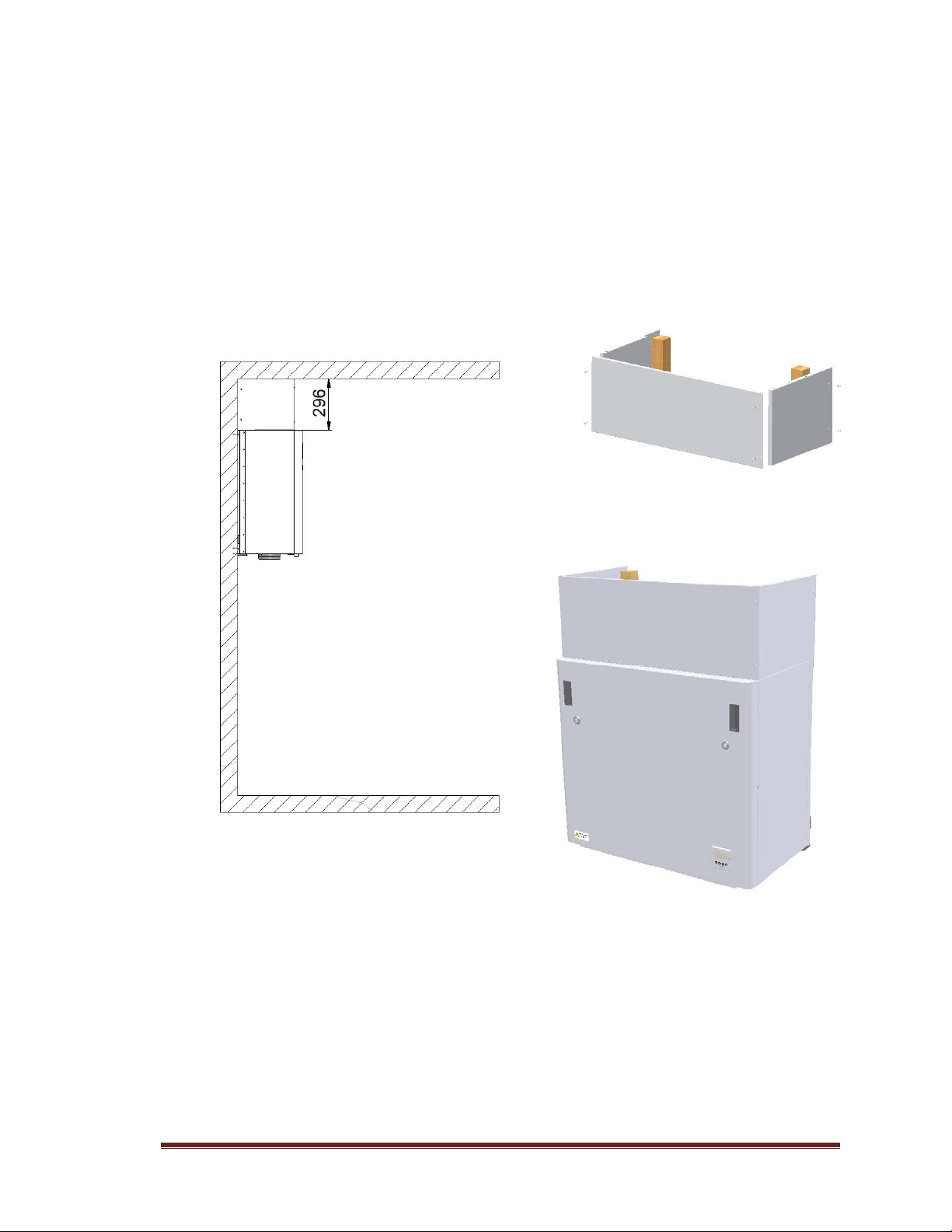
Theunitcanalsobeplacedonthefloor.Itisthenimportantthatthereareplacedatleast50mm
insulationundertheunittopreventvibrationtothebuilding.Ifventilationunitwillbeplacedasthe
sketchshowsitmustnotbecoveredsothatserviceisprevented.
Ifplacedattheatticmakesurethatthere
areatleast500mmclearanceoverthefront
hatchsotherewillberoomforservice.
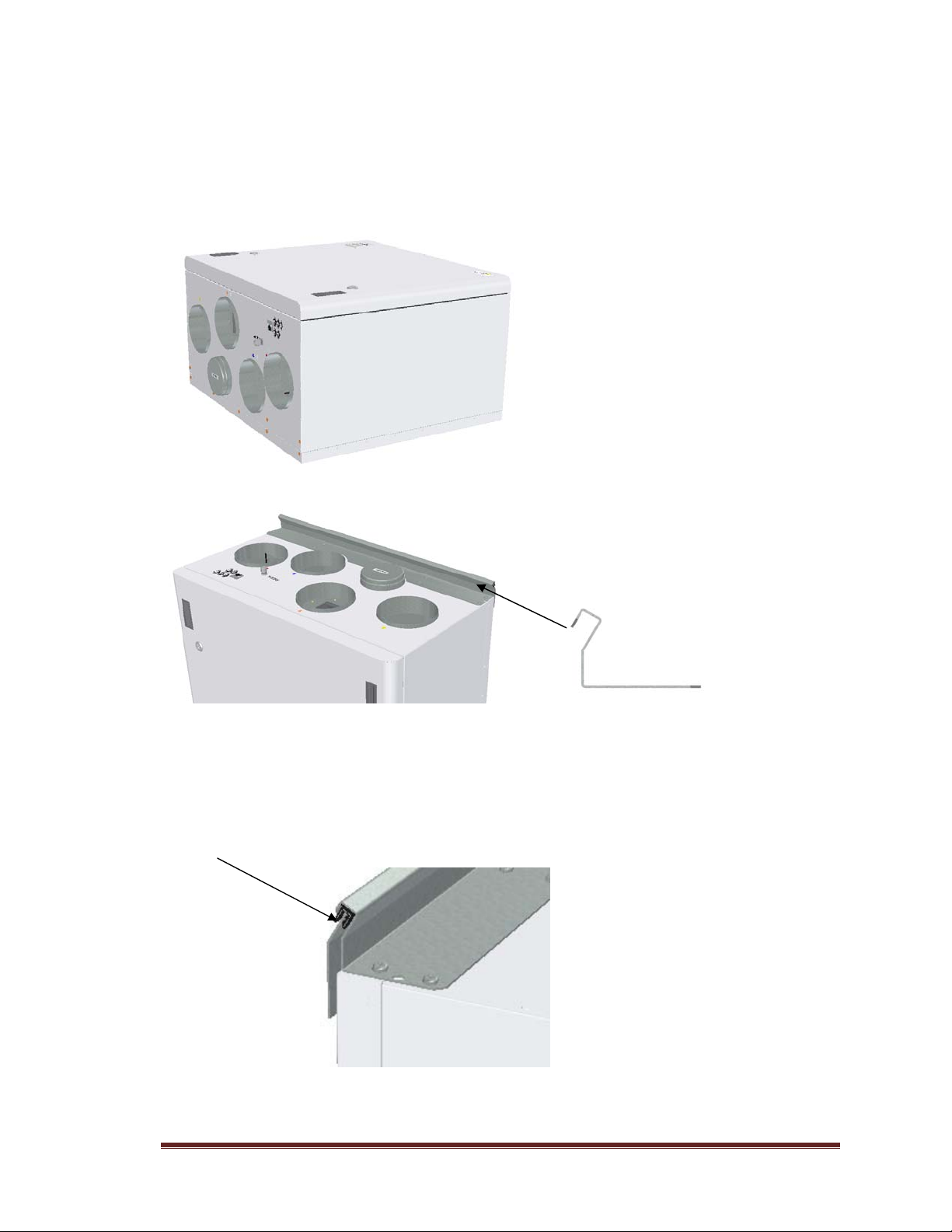
2.1Bracketsandvibrationgasket
Suspensionbracketscrewedontopofthe
unitasshown.
Use8pcsM5x16mm,suppliedwiththeunit
(SketchovershowAHU‐400BV)
Makesurethattheedgeprotectiongasketisplacedonthewallbracket.

393805‐2Rev0:05.05.2017.KJK
Wereservetherighttochangetechnicaldatawithoutnotice.http://www.ensy.noPage17
Togettheunitinrightpositionusethe
followingbracketsandscrews.Inorderto
reliefthehangerbracketonthetopitis
importanthoweveralsotomountthebracket
tobeundertheunit.Ensurethatthescrews
hitthebeamsbehindthewalliftheunitisto
behungonalightwall.
Use6pcswoodscrews5x40mm,supplied
withtheunit,foreachbracketMonter
veggfestetmedvibrasjonspakning.Påseat
vibrasjonspakningenerintakt.
Mountthewallbracketwithvibrationgasket.
Besurethatthevibrationgasketisintact
Gluevibrationgaskettothebackoftheunit,seeillustration.Approx.60mmfromthebottomofthe
unit.
2.2Stopperbrackets
Topreventtheunittobeliftedoutofthebracketsshouldbeinstalledtwostoppers.Usetwopcsof
woodscrews5x40mm,suppliedwiththeunit,foreachbracket.Inordernottotransmitvibration,itis
gluedvibrationmaterialonthesebrackets

393805‐2Rev0:05.05.2017.KJK
Wereservetherighttochangetechnicaldatawithoutnotice.http://www.ensy.noPage18
2.3Mountingofcookerhood
Ifkitchenexhausthoodistobeusedtogetherwiththeunit
Ifkitchenexhausthoodistobeconnected
intothetopoftheunit,youmustremovethe
endcapinthetopthatismarked“COOKER
HOOD”
(SketchshowsAHU‐400BV)
(SketchshowsAHU‐400BH)
393805‐2Rev0:05.05.2017.KJK
Wereservetherighttochangetechnicaldatawithoutnotice.http://www.ensy.noPage19
2.4Ductcover
Ifyouwanttouseaductcovertohidethepipingsyouwillneedthedistance296mmfromtheroof
anddowntothetopofunit.
Theductcoverhastobeorderedseparatelyfromsupplier.(Art:0100307‐2)
Theinstructionhowtomountthisductcoveryouwillfindtogetherwiththeductcover.
This manual suits for next models
1
Table of contents
Other Ensy Fan manuals


Popular Fan manuals by other brands


Bestron
Bestron ADV45S instruction manual

Sencor
Sencor ULTRASILENT SFE 2340WH Translation of the original manual

Uberhaus
Uberhaus PRO FE45-H1 Operator's manual
 8504103 REV D... manual")
TJERNLUND
TJERNLUND SS1C SIDESHOT WITH UC1 UNIVERSAL CONTROL (VERSION X.06) 8504103 REV D... manual

Hunter
Hunter 25703 owner's guide

Vents-us
Vents-us HRV 80 user manual


