Enthuze ENT5089 Quick setup guide

1
INSTRUCTIONS FOR ASSEMBLY AND USE OF ITEM: ENT5089
800 LBS UNIVERSAL OVER-CAB ALUMNIUM TRUCK RACK
Enthuze Automotive Products
email: [email protected]
website: www.enthuze.ca

2
Read and understand all warnings, cautions, and assembly, installation and use instructions prior to assembling,
installing or using this product. Failure to follow all warnings, cautions and instructions may result in serious injury.
The warnings, cautions, and instructions in this manual cannot cover all possible conditions or situations that could
occur. Exercise common sense and caution when using this truck rack. Always be aware of the environment and
ensure that the rack is used in a safe and responsible manner.
NEVER allow other persons to assemble, install or use this product until they have read this manual and have
developed a thorough understanding of how the product works.
NEVER attempt to modify this product or subject it to an installation or use for which it was not designed. Doing so
may result in damage and/or serious injury.
SAVE THESE INSTRUCTIONS IN A SAFE PLACE FOR FUTURE REFERENCE
ASSEMBLY, INSTALLATION, USE AND PERSONAL SAFETY PRECAUTIONS
•Park your truck on a level, hard surface well away from hazards. Place transmission in park and set the parking
brake with engine off. If working indoors, ensure adequate clearance for installation and exit prior to starting.
•ALWAYS follow all federal and state department of transportation regulations governing installation and use.
•Verify that installation surface has no hidden wires before installing.
•NEVER allow the rack to come into contact with an electrical source. The rack is not insulated and contact will
cause electrical shock.
•ALWAYS wear appropriate safety gear such as ANSI-approved safety goggles and heavy-duty work gloves when
assembling, installing, loading, unloading or removing/storing the rack.
•NEVER attempt to assemble, install, load or unload the rack while you are tired or under the influence of drugs or
alcohol.
•Keep children and bystanders away from the work area while assembling, installing, loading/unloading the rack.
•ALWAYS thoroughly inspect your rack for loose parts and/or signs of damage prior to each use, installation or
removal.
•NEVER use your rack until any loose parts have been properly secured or damaged parts have been properly
replaced.
•Maximum weight capacity rating applies only to an evenly distributed and properly secured load on a properly
installed rack.
•NEVER exceed the evenly distributed maximum weight capacity of this rack.
•NEVER exceed the rated maximum weight capacity of the truck on which this rack is installed. Refer to the truck’s
Gross Vehicle Weight Rating.
•Carrying any load can be hazardous. All loads must be tied down securely to the rack to prevent them from
changing position or coming loose as a result of wind, road hazards or vehicle movement.
•Top heavy loads increase the chance of rollover. High loads must be transported with GREAT CAUTION to avoid
striking objects with low clearance or vehicle tipping during turns, sudden maneuvers or high winds.
•Be aware of dynamic loading! Sudden load movement may briefly create excess load causing product failure.
Technical Specifications
Property
Specification
Length
133in.
Width
70.5in.
Height
36.5in.
Maximum Weight Capacity
800lbs.

3
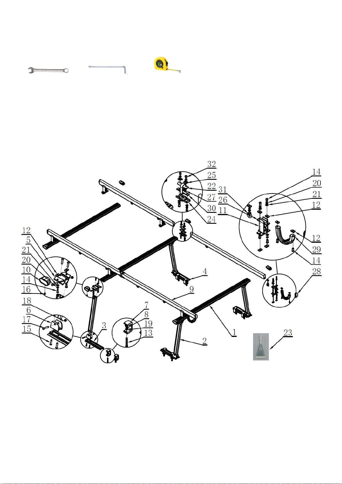
PARTS LIST
Prior to assembly and installation, make sure all parts are present, intact and undamaged. If you discover missing
and/or damaged parts, please contact our customer service using the information on page 1.
Item#
Description
Picture
Quantity
Item#
Description
Picture
Quantity
1
Crossbar
3
17
M10x55 Button Head Screws
8
2
Support Bar
4
18
M10 Lock Nut
8
3
Driver Side Front/Passenger
Side Rear Leg Rail Mount
2
19
M10 Hex Nut
8
4
Passenger Side Front/Driver
Side Rear Leg Rail Mount
2
20
Spring Washer
48
5
Upper Connecting Plate
4
21
Flat Washer
44
6
Lower Connecting Plate
4
22
Connecting Plate
2
7
C-Clamp
8
23
Thread Glue
1
8
Clamp Bolt Foot
8
24
Splint
2
9
Side Rail
4
25
Washer
4
10
Crossbar End Cap
6
26
Connecting Plate
6
11
Connecting Base
6
27
Plastic Sleeve
2
12
M10 Nut
44
28
Side Rail End Cap
4
13
M10x75 Hex Head Bolt
8
29
Handle
2
14
M10x25 Button Head Screws
36
30
Thread Block
2
15
M10x40 Button Head Screws
16
31
Ring Bolt
8
16
ST4.8×16 Phillips Head
Self-Tapping Screws
6
32
M10x16 Button Head Screws
8
4
Tools Required
Open Wrench (1 pc.) Allen Wrench (1 pc.) Tape Measure (1 pc)
Size=17mm Size=6mm
ASSEMBLY/PARTS DIAGRAM
5
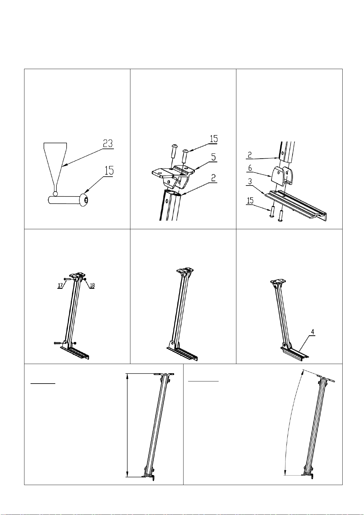
ASSEMBLY PROCEDURES
Step 1: Support Arm Assembly
①ATTENTION! All M10x40
Button Head Screws (15), require
a drop of thread glue (23), and
installation/tightening within 2
minutes of glue application.
②Connect Upper Connecting
Plate (5), on Support Bar (2), and
secure with M10x40 Button
Head Screws (15), as shown.
Note: Use Thread Glue (23), on
screws as noted in ①.
③Connect Driver Side Front
Leg Rail (3), & Lower Connecting
Plate (6), to bottom of support
bar (2), using M10x40 Button
Head Screws (15), as shown.
Note: Use Thread Glue (23), on
screws as noted in ①.
④Secure Upper (5), and Lower
(6), Connecting Plates using
M10x55 Button Head Screws
(17) and M10 Lock Nuts (18), as
shown.
⑤The front driver side support
arm is now assembled. Confirm it
is correct using the diagrams
below.
⑥Repeat this support arm
assembly procedure using the
Passenger Side Front Leg Rail
Mount (4). Then complete the
rear support arms in the same
manner.
CORRECT assembly example
for front and rear driver side
support arms.
The upper connecting base (5),
is level and parallel to rear leg
rail mount (3).
INCORRECT assembly
example for front and
rear driver side support
arms.
The upper connecting base (5),
is not level and parallel to rear
leg rail mount (3), because it is
facing the wrong direction.

6
STEP 2. Crossbar Installation
①Attach Spring Washers (20),
Flat Washers (21), to M10x25
Button Head Screws (14), and
secure to upper connecting plate
(5), with M10 Nuts (12), as
shown. Do NOT tighten. Repeat
process for all four support arms.
②Support arms are now ready
for crossbar installation.
③Slide the center channel of
the Crossbar (1), onto the M10
Nuts (12), at the top of the
support arms as shown. Only
finger tighten bolts at this stage
to allow for crossbar positioning.
④Place the rack assembly on the truck and center the crossbar on the support arms as shown. Once all
is properly positioned, the M10x25 Button Head Screws (14), can be tightened to lock the crossbar in
place on the support arms. Repeat the same process for the rear rack assembly.
Equal overhang on both sides
Driver
Side
Passenger
Side

7
STEP 3. Installation
①Attach an M10x75 Hex Head
Bolt (13), and M10 Hex Nut (19),
to each of the eight C-Clamps (7),
as shown.
②Position C-Clamp (7), close to
the base of the support arm so
that the tongue on the upper jaw
engages the groove in the Leg
Rail Mount (3), or (4). Place a
Clamp Bolt Foot (8) on the end of
the M10x75 Hex Head Bolt (13),
as shown.
③Tighten the M10x75 Hex
Head Bolt (13), and the M10 Hex
Nut (19), until entire assembly is
firmly affixed to the truck bed
rail. Install a second C-Clamp to
the same Leg Rail Mount at least
4” from the first.
④Continue the above procedure until you have installed two C-Clamps to each of the four Leg Rail
Mounts, securely affixing both crossbar assemblies to the truck bed rails as shown. WARNING! ALL
EIGHT C-CLAMPS MUST BE PROPERLY INSTALLED AS SHOWN FOR SAFE OPERATION OF THIS RACK.
Position clamps at
least 4” apart
8
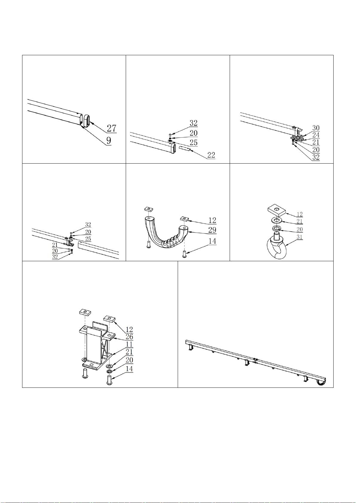
STEP 4. Side Rail Assembly and Installation
①Attach plastic sleeve (27), to
end of Side Rail (9), as shown.
②Attach Connecting Plate (22),
to end of Side Rail (9), using
M10x16 Button Head Screw (32),
Spring Washer (20), and Washer
(25), as shown.
③Attach Splint (24), and
Thread Block (30), to one end of
Side Rail (9), using M10x16
Button Head Screw (32), Spring
Washer (20), and Flat Washer
(21), as shown.
④ Attach a second Side Rail (9)
using the bolts and washers
shown below. Next, alternate
steps ⑤, ⑥ and ⑦ to achieve
side rail assembly configuration
shown in ⑧.
⑤Attach Handles (29), to end
of Side Rails as shown in ⑧
using M10x25 Button Head
Screws (14), and M10 Nuts (12).
⑥Attach Ring Bolts (31), to
bottom of Side Rails (9), using
Spring Washers (20), Flat
Washers (21), and screw M10
Nut (12).
⑦ Install Connecting Plates (26), on Connecting
Bases (11), and attach to bottom of Side Rails (9),
using M10x25 Button Head Screws (14), Spring
Washers (20), Flat Washers (21), and M10 Nuts
(12). Do not tighten until installed on crossbars.
⑧ Repeat steps ① through ⑦ to complete two
side rail assemblies configured as shown below.
Note: Connecting Bases (11), cannot be positioned
under the joints linking the two side rail sections.

9
⑨ Attach side rail assemblies to crossbars using
M10x25 Button Head Screws (14), Spring Washers
(20), Flat Washers (21), and M10 Nuts (12). Do
not tighten until both side rails assemblies are
properly positioned on the crossbars.
⑩Tighten all 16 of the M10x25 Button Head
Screws (14), on the four Connecting Bases (11),
linking the side rails to the two rear crossbars
prior to installing and securing the front-most
crossbar.
STEP 5. Completing your rack.
①Install all six Crossbar End Caps (10), and
secure in place using ST4.8×16 Phillips Head
Self-Tapping Screws (16), as shown.
②Install the four press-fit Side Rail End Caps as
shown.

10
③ Check to make sure all hardware has been securely tightened. Depending on the configuration of
your truck, your installed rack should resemble this diagram. Congratulations, your rack is now ready for
use. Please remember to haul your loads safely.
Table of contents
Other Enthuze Automobile Accessories manuals


