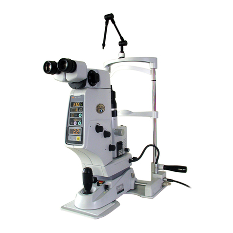
Nidek Medical YC-1600 User manual

NIDEK
OPHTHALMIC YAG LASER SYSTEM
Model YC-1600
SERVICE MANUAL
XYC14*RDA001E/E
Total pages: 105
2005.3.3

HEAD OFFICE : 34-14, Maehama, Hiroishi-cho, Gamagori, Aichi 443-0038, Japan
Telephone: (0533) 67-6611
Facsimile: (0533) 67-6610
TOKYO OFFICE : 6th Floor, Takahashi Bldg., No.2, 3-chome, Kanda-jinboucho
(International Div.) Chiyoda-ku, Tokyo 101-0051, Japan
Telephone: (03) 3288-0571
Facsimile: (03) 3288-0570
Telex: 2226647 NIDEK J
NIDEK INCORPORATED : 47651 Westinghouse Drive Fremont, California 94539, U. S. A.
Telephone: (510) 226-5700
Facsimile: (510) 226-5750
NIDEK SOCIETE ANONYME : Europarc 13, rue Auguste Perret, 94042 CRETEIL, France
(Représentant Autorisé) Telephone: (01) 49 80 97 97
Facsimile: (01) 49 80 32 08 Printed in JAPAN

Table of Contents
§1
INTRODUCTIONS ......................................................................................................1-1
1.1Beforeusingthismanual..............................................................................................1-1
1.2Beforerepairing..........................................................................................................1-1
1.3Handlingandrepairingofthelaser head ......................................................................1-1
1.4Handling andrepairing oftheboardandwiring ............................................................1-1
§2
CAUTIONS................................................................................................................... 2-1
2.1 Cautions in laser emission........................................................................................ 2-1
2.2 Handling of the laser head........................................................................................2-1
2.3 Boards for repair.......................................................................................................2-1
2.4 Cautions in checking connectors..............................................................................2-1
2.5 Cautions in disconnecting cords...............................................................................2-2
2.6 Cautions in soldering cords ...................................................................................... 2-2
2.7 Cautions in using the energy meter for the YAG laser ............................................. 2-2
§3
TROUBLESHOOTING ..............................................................................................3-1
§4
SUB TROUBLESHOOTING......................................................................................4-1
4.1 The pilot lamp does not light....................................................................................4-1
4.2 Both fixation lamp and backlight of the control panel do not light .........................4-2
4.3 Only fixation lamp does not light.............................................................................4-3
4.4 Only backlight of the control panel does not light ...................................................4-3
4.5 The error display appears .........................................................................................4-4
4.5.1 Error 1 appears................................................................................................ 4-4
4.5.2 Error 4 appears................................................................................................ 4-4
4.5.3 Error 5 appears................................................................................................ 4-5
4.5.4 Error 7 appears................................................................................................ 4-6
4.5.5 Error 10 appears.............................................................................................. 4-8
4.5.6 Error 12 appears.............................................................................................. 4-9
4.5.7 Error 13 appears.............................................................................................. 4-9
4.5.8 Error 14 appears............................................................................................ 4-10
4.5.9 Error 15 appears............................................................................................ 4-11
4.5.10 Error 30 appears.......................................................................................... 4-12
4.5.11 Error 31 appears..........................................................................................4-13
4.5.12 Error 50 appears.......................................................................................... 4-14
4.5.13 Error 51 appears.......................................................................................... 4-14
4.5.14 Error 52 appears.......................................................................................... 4-15
4.5.15 Error 53 appears.......................................................................................... 4-15
4.5.16 Error 54 appears ..........................................................................................4-16
4.5.17 Error 90 appears ..........................................................................................4-16
4.6Theilluminationlightisnotprojected .........................................................................4-17

4.7Thefocusingrodlooks likeshiftingwhenthePD isadjusted ......................................4-18
4.8Theilluminationlightisshiftedfromthecenterof
Microscopic visual field when the magnification is 10× ...................................... 4-18
4.9 The focusing rod cannot be seen clearly ................................................................ 4-18
4.10 There are some spots in the illumination light .....................................................4-19
4.11 The illumination light is not focused on the focusing rod.................................... 4-19
4.12 The position of illumination light on the focusing rod is not normal .................. 4-19
4.13 The illumination light does not go out even if the Brightness
control is turned fully counterclockwise............................................................. 4-19
4.14 The slit image tilts when turning it to the vertical position.................................. 4-20
4.15 The slit does not fully close or open.....................................................................4-20
4.16 The position where the slit closes is shifted from the center ...............................4-20
4.17 Coarse movement to back and forth is not smooth ..............................................4-21
4.18 Coarse movement to right and left is not smooth.................................................4-21
4.19 Fine movement to back and forth, and to right and left is not smooth.................4-22
4.20 Vertical movement is not smooth ......................................................................... 4-22
4.21 Aiming beam is not emitted .................................................................................4-23
4.22 The STATUS indicator for READY mode does not light ....................................4-23
4.23 The position of burnt pattern is not same to the projected position
of the aiming beam ............................................................................................. 4-23
4.24 There is an unevenness in the burnt pattern .........................................................4-24
4.25 Setting of the number of pulses cannot be changed .............................................4-25
4.26 Counter display cannot be reset to “0”.................................................................4-25
4.27 The measured energy of YAG laser beam is not normal ...................................... 4-26
4.28 The system does not stop with the Emergency stop switch ................................. 4-26
§5
REPAIR.........................................................................................................................5-1
5.1 Removing covers......................................................................................................5-1
5.1.1 Right cover .....................................................................................................5-1
5.1.2 Left cover.........................................................................................................5-2
5.1.3 Bottom cover of the microscope arm.................................................................5-2
5.1.4 Cover of the microscope arm ............................................................................5-2
5.1.5 Front cover ......................................................................................................5-3
5.1.6 SL cover B .......................................................................................................5-3
5.1.7 SLcover A .......................................................................................................5-3
5.1.8 Switch box .......................................................................................................5-4
5.1.9Right coverof thelamphousing .........................................................................5-4
5.1.10Leftcover ofthelamp housing.........................................................................5-5
5.1.11Coverof theaimingadjustment part.................................................................5-5
5.2 Check and replacement of fuses..................................................................................5-5
5.3Voltagecheckfor walloutlet .......................................................................................5-6
5.4Replacementofkeycontrolswitch..............................................................................5-6
5.5Replacementofthepilotlamp .....................................................................................5-6
5.6ReplacementoftheEmergencystopswitch .................................................................5-7
5.7Replacement ofthefixationlampASSY ......................................................................5-7
5.8Replacementoftheswitchingpowersupply.................................................................5-8
5.9 Replacement of the master board ................................................................................5-8
5.10 Replacement of the focusASSY ...............................................................................5-9

5.11 Replacement of the display boardASSY .................................................................5-10
5.12ReplacementoftheYAGlaserunit ..........................................................................5-10
5.13Replacementof theenergymonitorASSY...............................................................5-12
5.14 Replacement of the rack .........................................................................................5-12
5.15Replacementofthewheelshaft ...............................................................................5-13
5.16Replacementofthe plate.........................................................................................5-13
5.17ReplacementoftheYAG shutterASSY...................................................................5-14
5.18Replacement oftheaimingshutterASSY.................................................................5-14
5.19 Replacement of theYLcableASSY........................................................................5-15
5.20 Replacement of theYLpower supply board ............................................................5-15
5.21ReplacementoftheilluminationASSY.....................................................................5-16
5.22Replacement oftheverticaldrivingaxelofthe chinsupport ......................................5-17
§6
VERIFICATIONANDADJUSTMENT ........................................................................ 6-1
6.1Adjustmentofthe microscopeandbinocular tube ........................................................6-1
6.1.1 Check of the optical axis of microscope ............................................................6-1
6.1.2Adjustmentoftheopticalaxiswiththebinoculartube .........................................6-1
6.1.3Adjustmentoftheprism holderposition .............................................................6-2
6.1.4Adjustment oftheoptical axiswiththe microscopehead ....................................6-3
6.2Adjustmentoftheilluminationpart ...............................................................................6-4
6.2.1Cleaningoftheopticalsystemforillumination.....................................................6-4
6.2.2Cleaningofthefilters.........................................................................................6-5
6.2.3Cleaningoftheslit.............................................................................................6-5
6.2.4Adjustmentofthefocusofillumination ...............................................................6-6
6.2.5Illuminationfocusadjustmentfortheprismhead
without tilting mechanism .............................................................................. 6-7
6.2.6 Illumination focus adjustment for the prism head
with tilting mechanism .................................................................................... 6-7
6.2.7 Check of the optical axis of illumination........................................................6-9
6.2.8 Adjustment of the optical axis of illumination (horizontal) ...........................6-9
6.2.9 Adjustment of the optical axis for prism head
withtiltingmechanism (vertical) ..........................................................................6-9
6.2.10Adjustment oftheoptical axis forprismhead
with tilting mechanism (vertical) ......................................................................6-10
6.2.11Adjustmentoftheverticalpositionofslit ........................................................ 6-11
6.2.12Adjustmentof theclosingofslit .....................................................................6-12
6.2.13Checkandadjustmentofthehorizontalslitimage...........................................6-13
6.2.14Checkand adjustmentof theverticalslit image ..............................................6-15
6.2.15Adjustmentoftheslitshutterposition(horizontal) ...........................................6-15
6.2.16Adjustmentoftheslitshutterposition(vertical)...............................................6-16
6.3Adjustmentoftheaimingbeam..................................................................................6-17
6.3.1Fixingtheaimingshutterplate ..........................................................................6-17
6.3.2Checkofthe sensor foraimingshutter .............................................................6-18
6.3.3Adjustmentof theopticalaxisofaimingbeam ..................................................6-19
6.3.4Focusadjustment ofthe aimingbeam ..............................................................6-19
6.3.5Adjustmentoftheopticalaxisoftwo-pointaimingbeams .................................6-19
6.3.6Adjustmentoftheaimingenergy ......................................................................6-20
6.3.7Adjustmentofthemaximumenergy .................................................................6-21
6.3.8Adjustmentoftheminimumenergy ..................................................................6-21

6.4Adjustment oftheYAG laser.....................................................................................6-22
6.4.1AdjustmentoftheYAGshutter ........................................................................6-22
6.4.2 Check of the sensor forYAG shutter ...............................................................6-23
6.4.3Adjustment of theindicatedand measured valuesofPFNvoltage.....................6-23
6.4.4Adjustment of the PFN voltage .......................................................................6-25
6.4.5Adjustment of themirrorholder 3 and opticalaxisof
YAG laser head ..............................................................................................6-27
6.4.6Adjustment of the focusASSY ........................................................................6-27
6.4.7Adjustment of theDmirrorASSY
(aligning theYAG laser beam to the aiming beam) ............................................6-28
6.4.8Adjustment of thefocusofYAG laser ..............................................................6-28
6.4.9Adjustmentof thefocusshift............................................................................6-29
6.4.10Adjustment oftheYAG laserenergy ..............................................................6-30
6.5Otheradjustments ....................................................................................................6-35
6.5.1Adjustmentofthesmoothness ofverticalmovement .........................................6-35
6.6Adjustmentofindicatedenergyfrom outsideof thedevice andsettable function..........6-36
6.6.1Adjustmentofindicated energyofYAGlaser ...................................................6-36
6.6.1.1Gain adjustment .................................................................................6-36
6.6.1.2Offsetadjsutment...............................................................................6-36
6.6.2Adjustmentofaimingenergy ..................................................................................6-36
6.6.2.1Aiminggainadjsutment .......................................................................6-36
6.6.2.2Aimingoffsetadjustment.....................................................................6-36
6.6.3Releaseoftiltinglens-barrel(option)control ....................................................6-37
§7
WIRING DIAGRAM ................................................................................................... 7-1
§8
ERROR CODE LIST ................................................................................................... 8-1
8.1 Error code list ............................................................................................................8-1
8.2Dip switchlist .............................................................................................................8-2
8.3Otherindications ........................................................................................................8-3
§9
SYSTEM PARAMETER LIST .................................................................................... 9-1
9.1Changingandsettingoftheparameters........................................................................9-1
9.2Originalsettingofthe systemparameters .....................................................................9-2
9.3 Contents of parameters...............................................................................................9-3
§
10
LIST OF PARTS TO BE REPLACED ......................................................................10-1
10.1 Consumables ........................................................................................................ 10-1
10.2 Parts to be repaired and replaced..........................................................................10-1
§
11
TOOLS, MEASUREMENT DEVICE, SOLVENTAND JIGS ............................... 11-1
11.1Tools...................................................................................................................... 11-1
11.2 Measurementdevice ............................................................................................... 11-1
11.3Solvent ................................................................................................................... 11-1
11.4Jigs......................................................................................................................... 11-1
11.5 Others.................................................................................................................... 11-1

XYC14*RDA001E/E
§1 INTRODUCTION
1 - 1
1.1 Before using this manual
• Thisservicemanual is fortheOPHTHALMICYAG LASER SYSTEMYC-1600.
• Be sure to use this manual after understanding the operator’s manual for the OPHTHALMIC
YAG LASER SYSTEM YC-1600 thoroughly.
• This manual is subject to change without notice for improvement. Since the Technical Bulletin
will be released every time significant changes are made to the system, refer to the Technical
Bulletin together with this manual.
1.2 Before repairing
• Be sure not to lose or drop the removed screws inside the system.
• Apply a threadlocker to the screws which have been loosened and tightened again.
• Refer to the wiring diagram of the YC-1600 when repairing (see 7.1).
1.3 Handling and repairing of the laser head
• Be sure to turn OFF the power of the system when handling the laser head.
• Be sure to return the laser head to NIDEK for repair. Never disassemble, adjust and repair the
laser head.
NIDEK assumes no responsibility if the laser head is disassembled, adjusted and repaired.
1.4 Handling and repairing of the board and wiring
• Be sure to turn OFF the power of the system when handling and repairing the board and
wiring.
[WARNING]
Since Nd:YAG laser is an invisible infrared ray, it may cause the hazardous exposure to
radiation if the system is improperly handled and operated.
[CAUTION]
Be sure not to expose yourself to the laser beam at a place where the laser beam passes
through or is emitted when handling and repairing.
[CAUTION]
Be sure to use the safety goggles for the Nd:YAG laser.

XYC14*RDA001E/E
1 - 2
[CAUTION]
Neverlookstraightat the Nd:YAGlaserevenif the safetygogglesare used.
[CAUTION]
Nevertouchtheoptical parts suchasmirrors and lensdirectly.
[CAUTION]
Never emit the laser beam to the skin.
[CAUTION]
Pay attention not to get an electric shock when unavoidably opening covers to check or repair
the electrical parts.

XYC14*RDA001E/E
§2 CAUTIONS
2 - 1
2.1 Cautions in laser emission
• Never emit the laser beam to personnel or things.
• Never touch the high voltage part (shown with mark) when emitting the laser beam since
there is a fear of an electric shock.
• Be sure not to drop metallic parts such as tools and screws into the laser system.
2.2 Handling of the laser head
• Never disassemble or repair the laser head.
Return the laser head to NIDEK if the repair is necessary.
2.3 Boards for repair
• The IC8 (EEPROM) on the MASTER BOARD which is supplied by NIDEK has already been
placed in the initial state. The setting values memorized in each EEPROM become optimum
for each system’s performance. As a result, the setting values may be varied according to each
system.
If using a new board, remove the IC8 (EEPROM) from the old one and attach it to a new one.
2.4 Cautions in checking connectors
• Visually check the connecting condition of connectors.
If the connector is almost disconnected, securely reconnect it.
• Verify the conditions of the contact pins and contacts.
• Cleaning of the contact pins
Clean the contacts with a spray which restores electrical continuity to them when dust or
oil makes them dirty.
• Verify the condition of the contact pins and contacts.
Disconnect the connectors and verify each cord by pulling a cord with the force approx. 1
kgf.
If the contact pin is removed, raise the hook of the pin using the precise screwdriver, and
insert it into the connector.

XYC14*RDA001E/E
2 - 2
2.5 Cautions in disconnecting cords
• If the heat-shrinkable tube covers the cord, remove it using nippers or knife.
• Use the soldering iron to remove the soldered parts.
• Remove the old solder adhered to the cord or terminal with the soldering iron.
2.6 Cautions in soldering cords
• If the cord was covered by the heat-shrinkable tube, run the cord through the tube.
• Solder the cords to bundle them before soldering the cord.
• Put the heat-shrinkable tube on the soldered part and constrict it using a heat gun.
2.7
Cautions in using the energy meterfortheYAGlaser
• According to the energy meter to be used, the necessity of the dispersion lens, which is attached
to the objective lens at the time of the energy measurement, is varied.
Refer to the table below when measuring the energy.
• There is a fear that the detector of the energy meter is damaged if the excessive energy density
is applied to the photoreceptor of the detector.
Be sure to maximize the spot size of the aiming beam on the photoreceptor as possible so that
the YAG laser never come into focus on the photoreceptor.
Energy meter Dispersion lens
MODEL-365 Necessary
MODEL PHDX50 Unnecessary

XYC14*RDA001E/E
§3 TROUBLESHOOTING
3 - 1
Plug the power cord to the wall outlet.
Does the pilot lamp light?
Insert the key and turn to the ON ( )
position.
Do the fixation lamp and backlight of the
control panel light?
Does the error display appear?
Removethecap and insertthefocusing rod.
Istheilluminationlightprojectedonthefocusing
rod?
Adjust the dioptric power of the eyepieces.
Adjust the PD of the microscope.
Is the condition of the optical system of the
microscope normal?
Is the condition of the illumination normal?
4.1 The pilot lamp does not light
4.2 Both fixation lamp and backlight of the
control panel do not light
4.3 Only fixation lamp does not light
4.4 Only backlight of the control panel does
not light
4.5 The error display appears
4.6
The illumination light is not projected
4.7 The focusing rod looks like shifting when
the PD is adjusted
4.8 The center of illumination light is shifted
from the center of Microscopic visual
field when the magnification is 10×
4.9 The focusing rod cannot be seen clearly
4.10 There are some spots in the
illumination light
4.11 The illumination light is not focused
on the focusing rod
4.12 The position of illumination light on
the focusing rod is not normal
4.13 The illumination light does not go out
even if the Brightness control is turned
fully counterclockwise
Y
N
N
Y
N
N
Y
Y
N
Y
N
Y

XYC14*RDA001E/E
3 - 2
Is the condition of the slit normal?
Is the movement of the slit lamp normal?
Reduce the light amount of the slit lamp.
Can the aiming beam be seen?
Remove the focusing rod and attach the
cap.
Stick the burn paper to the head rest.
Turn the Energy control to set the output
energy to minimum.
Turn the YAG Focus shift control to “0”
position.
Do the STATUS indicator for STANDBY
mode go off and the one for READY mode
light when the STATUS switch is pressed?
Is theYAG laser beam emitted normally when
the trigger switch is pressed?
4.14 The slit image tilts when turning it to
the vertical position
4.15 The slit does not fully close or open
4.16 The position where the slit closes shifts
from the center
4.17 Coarse movement to back and forth is
not smooth
4.18 Coarse movement to right and left is
not smooth
4.19 Fine movement to back and forth, and
to right and left is not smooth
4.20 Vertical movement is not smooth
4.21 Aiming beam is not emitted
4.22 The STATUS indicator for READY
mode does not light
4.5 The error display appears
4.23 The position of burnt pattern is not
same to the projected position of the
aiming beam
4.24 There is an unevenness in the burnt
pattern
N
Y
Y
Y
Y
Y
N
N
N
N

XYC14*RDA001E/E
3 - 3
Can the setting of the number of pulses
be changed when the Burst switch is
pressed?
Is the counter reset to “0” when the Reset
switch is pressed?
Is the energy of the emitted YAG laser beam
normal?
Does the system stop when the Emergency
stop switch is pressed?
Turn the key switch to OFF ( ) position and
pull out the key.
End
4.25 Setting of the number of pulses can not
be changed
4.26 Counter display cannot be reset to “0”
4.27 The measured energy of YAG laser
beam is not normal
4.28 The system does not stop with the
Emergency stop switch
Y
N
Y
Y
Y
N
N
N

XYC14*RDA001E/E
3 - 4

XYC14*RDA001E/E
§4 SUB TROUBLESHOOTING
4 - 1
4.1 The pilot lamp does not light
This trouble may be caused by the break of fuses in the switch box, failure of the switching
power supply, and connection failure of connectors.
Is there continuity in F1 and F2 fuses in the
switch box?
(See 5.2.)
Is the required voltage applied to the wall
outlet?
(See 5.3.)
Is the voltage between 1(-) and 2 (+) of
P2 in the switching power supply DC
+12V?
Is the voltage between 1 (+) and 2 (-) of P501
on the key switch board DC +12V?
Is the voltage between 5 (+) and 6 (-) of P502
on the key switch board DC +12V?
Failure of the pilot lamp.
Replace it with a new one.
(See 5.5.)
Replace fuses.
(See 5.2.)
Secure the required voltage.
(See 5.3.)
Replace the switching power supply.
(See 5.8.)
Connection failure of the cable of P501 or
connector. Check the continuity and repair
the failed part.
Connection failure inside the key switch
board.
Replace the key switch board with a new one.
(See 5.4.)
Y
N
Y
N
N
Y
N
N
Y
Y

XYC14*RDA001E/E
4 - 2
4.2 Both fixation lamp and backlight of the control panel do not light
This trouble may be caused by the connection failure of connectors.
Is there no continuity between 2nd and 4th/
5th pin on the key switch when the key switch
is turned OFF?
Is there continuity between 2nd and 4th/5th
pin on the key switch when the key switch is
turned ON?
Is the Emergency stop switch normal?
Disconnect P3 of the remote connector.
Is there continuity between 3rd and 4th pin of
P3?
Reconnect connectors P501, P502, and P503
on the key switch board and P3 of the remote
connector.
Failure of the key switch.
Replace the key switch board with a new one.
(See 5.4.)
Replace the Emergency stop switch with a
new one.
(See 5.6.)
Connection failure between 3rd and 4th pins
of P3 of the remote connector.
Repair the failed part.
Y
N
Y
N
N
Y

XYC14*RDA001E/E
4 - 3
4.3 Only fixation lamp does not light
This trouble may be caused by the connection failure of connectors.
Is the voltage between 1 (+) and 2 (-) of P503
on the key switch board DC +12V?
Remove the fixation lamp ASSY.
Is the voltage between 1 (+) and 2 (-) of
P1 DC +12V?
Replace the fixation lamp ASSY.
(See 5.7.)
Connection failure inside the key switch
board.
Replace the key switch board with a new one.
(See 5.4.)
Connection failure of the cable between P503
and J13, between P13 and P1, or connectors.
Check the continuity and repair the failed
part.
N
Y
N
4.4
Only backlight of the control panel does not light
This trouble may be caused by the connection failure of connectors or failure of the master
board.
Are the following connections proper?
• P113 and P106 on the master board
• J201 on the display board, P501 on the
key switch board
• J5 of the external connector
Is the voltage between 1 (+) and 3 (-) of P113
on the master board DC +12V?
Is the voltage between 1 (+) and 2 (-) of P110
on the master board DC +5V?
Replace the display board ASSY with a new
one.
(See 5.11.)
Reconnect the connectors.
Break in the cable or connection failure
between PJ5 on the key switch board and
PJ113 on the master board.
Check the continuity and repair the failed
part.
Replace the master board with a new one.
(See 5.9.)
Y
N
N
Y
N
Y
Y

XYC14*RDA001E/E
4 - 4
4.5 The error display appears
4.5.1 Error 1 appears
Error 1 appears when the temperature inside the YAG laser head becomes 45 ºC or more.
Turn the key switch to the OFF position and
remove the right and left covers.
Set it aside for 30 minutes for cooling.
Is the resistance across TS1 on the master
board infinity?
Replace the master board with a new one.
(See 5.9.)
Failure of TS1.
Replace the master board with a new one.
(See 5.9.)
Y
N
4.5.2 Error 4 appears
Error 4 appears when the malfunction occurs to the contents of EEPROM.
Initialize the EEPROM.
(See 9.2.)
Reset the followings;
• Aiming energy
• PFN voltage
• Focus of the YAG laser
• YAG laser energy
(See 6.3.6, 6.4.3, 6.4.6, 6.4.10.)

XYC14*RDA001E/E
4 - 5
4.5.3 Error 5 appears
Error 5 appears when the YAG shutter does not open or close automatically.
The cause may be the failure of the detection sensor of the YAG shutter.
Does the YAG shutter open when the system
is in the READY state and close in the
STANDBY state?
Is the YAG shutter caught in cables?
Are the voltage between 5 (+) and 7 (-) of
P102 on the master board DC +5V, and
between 6 (+) and 7 (-) DC +0V when the
shutter close?
Is the detection sensor (photo-interrupter)
normal?
(See 6.4.1.)
Failure of the rotary solenoid.
Replace the YAG shutter ASSY with a new
one.
(See 5.17.)
Repair the part where the YAG shutter plate
is caught in.
Failure of the IC1 on the master board.
Replace the master board with a new one.
(See 5.9.)
Failure of the detection sensor.
Replace the YAG shutter ASSY with a new
one.
(See 5.17.)
Fix the rotary solenoid.
(Refer to 5.17.)
Is the rotary solenoid fixed firmly?
Adjust the YAG shutter ASSY.
(See 6.4.1.)
N
Y
Y
N
N
Y
N
Y
Y
N

XYC14*RDA001E/E
4 - 6
4.5.4 Error 7 appears
Error 7 appears in the case where the aiming shutter does not open automatically when the
aiming laser is ON or it does not close when the aiming laser is OFF.
The cause may be the failure of the detection sensor of the aiming shutter or the solenoid for the
aiming shutter.
• The aiming shutter does not open automatically when the aiming laser is ON.
Is the aiming shutter plate placed in the open
position?
Is the voltage between 4 (+) and 7 (-) of P103
on the master board DC 0V?
Failure of the IC1 on the master board.
Replace the master board with a new one.
(Refer 5.9.)
Is the voltage between 1 (+) and 2 (-) of
P103 on the master board DC +10V or
more?
Failure of the IC2 on the master
board.
Replace the master board with a
new one.
(See 5.9.)
Failure of the solenoid.
Replace the aiming shutterASSYwith a new
one.
(See 5.18.)
Adjust the position of the detection sensor
(photo-interrupter).
(See 6.3.1.)
N
Y
N
N
Y
Y
Table of contents
Other Nidek Medical Measuring Instrument manuals

Nidek Medical
Nidek Medical ARK-1S User manual

Nidek Medical
Nidek Medical LM-7 User manual

Nidek Medical
Nidek Medical OPD-Scan III User manual

Nidek Medical
Nidek Medical AR-600 User manual

Nidek Medical
Nidek Medical LM-1000 User manual

Nidek Medical
Nidek Medical OPD-Scan III User manual

Nidek Medical
Nidek Medical PM-700 User manual

Nidek Medical
Nidek Medical ARK-700 Series User manual

Nidek Medical
Nidek Medical LM-1800P User manual

Nidek Medical
Nidek Medical YC-1800 User manual