enviromental express AutoBlock Fill Administrator Guide
AutoBlock® Fill Filling Station
Operation & Instruction Manual
©2021 Environmental Express. All rights reserved.
July 2021 1065EE26_M Rev 2
+1.800.343.5319 or +1.843.881.6560 envexp.com

+1.800.343.5319 or +1.843.881.6560 envexp.com Environmental Express
AutoBlock® Fill: Operation and Instruction Manual Contents
Contents
General Information
Warranty and Repair Policy 1
Declaration of Conformity 2
About Your AutoBlock®Fill
Part Numbers / Model Information / Specications 3–4
Getting Started
Installation / Safety / Maintenance 4–7
Operation Using the AutoBlock® Fill Software on a PC 8–11
Operation Using Onboard Touch-Screen Controller 11–12
Parts and Supplies
Accessories 13
Adaptation of EPA Methods for Use with Your HotBlock®
Method 200.2, Revision 2.8 14–15
Method 200.7, Revision 4.4 16–17
Method 200.8 18–19
Methods 245.1, 7470, and 7471 for Mercury Digestions 20–21
Method 365.1 for Phosphorus 22
Method 3050B 23–24
NIOSH Method 7303 24–25
Sample Preparation for Lead Analysis using the GhostWipe® Wipes 25–26
Method 3060A for use with the HotBlock®and StirBase™ Systems 27–28

+1.800.343.5319 or +1.843.881.6560 envexp.com Environmental Express • 1
AutoBlock® Fill: Operation and Instruction Manual Warranty and Repair Policy
Loaner AutoBlock® Fill system MAY be available during the repair period. There are only a limited number of these units.
A reasonable charge for “cleanup” will be charged if a loaner is issued. The customer will be responsible for all shipping
charges associated with a loaner unit.
Limited Warranty
The Environmental Express AutoBlock® Fill is warranted against defects in materials and workmanship when used in
accordance with applicable instructions, for a period of one year from the date of shipment. This warranty extends
to parts, labor, and any approved transportation charges. This warranty applies only to damage or failure caused by
normal laboratory use. The warranty is limited to product repair. If Environmental Express is unable to repair the
AutoBlock® Fill, the customer may, at his or her option, receive a replacement unit or a full refund.
In no event shall Environmental Express have any obligation to make repairs, replacements or corrections required,
in whole or in part, as the result of (i) normal wear and tear, (ii) accident, disaster or event of force majeure, (iii)
abuse, neglect, misuse, fault or negligence of or by customer, (iv) use of the product in a manner for which it was not
designed, (v) causes external to the product such as, but not limited to, power failure or electrical power surges, (vi)
improper storage and handling of the product, (vii) use of the product in combination with equipment or software
not supplied by Environmental Express, (viii) ordinary maintenance, (ix) alterations, repairs or installations that have
not been performed by Environmental Express or its authorized representative or (x) failure to maintain product in
accordance with Environmental Express’ written instructions.
Environmental Express makes no other warranty, expressed or implied for this product with respect to merchantability,
tness for a particular use or any other matter and expressly disclaims all other warranties. Environmental Express
is not liable for any consequential, special, indirect or compensatory damages arising from use of, or in conjunction
with this product. the maximum liability of Environmental Express (whether by reason of breach of contract, tort,
indemnication, or otherwise, but excluding liability of seller for breach of warranty (the sole remedy for which shall
be as otherwise provided herein)) shall be the invoice price of this product.
Repair Policies
Note: This warranty does not apply to any consumable items associated with the AutoBlock® Fill system.
Under Warranty Repair:
If the AutoBlock® Fill should fail to operate as warranted
within the warranty period (one year from date of
shipment), Environmental Express will repair it and
ship it back to the customer at Environmental Express’
expense. The remainder of the warranty period will be
honored from the original ship date. Environmental
Express will bear the cost of ground transportation both
to and from the customer’s location, and bear the cost of
any parts, labor and cleanup required.
However, if it is determined that the damage to the
AutoBlock® Fill was caused by negligence or improper
use or by another excluded cause as set forth above,
this warranty will not apply. The warranty is also void
if the system is used beyond its intended purpose or
in the event of any unauthorized repair. In such cases,
reasonable and customary repair charges will apply.
Repair charges will be quoted prior to work being done.
Out of Warranty Repair:
If the AutoBlock® Fill fails after the warranty period has
lapsed, the repair procedure is as follows:
First, notify an Environmental Express Technical
Service Representative of product’s failure and place
an order for repair. Whenever possible, our customer
service technician will walk you through possible
troubleshooting scenarios which may enable you to
repair your block on-site.
If on-site repair is not possible, the customer may return
the non-working unit to Environmental Express using
appropriate shipping containers and insurance. Repair
charges will be assessed and estimated prior to work
being done. Repair charges will include all freight costs
as well as reasonable and customary charges for parts
and labor.

+1.800.343.5319 or +1.843.881.6560 envexp.com Environmental Express • 2
AutoBlock® Fill: Operation and Instruction Manual Declaration of Conformity
The manufacturer, Environmental Express, 2345A Charleston Regional Parkway, Charleston, SC 29492 declares
that the following product, AutoBlock® Fill Item Number ABF5000, is in conformity with:
4000040
Product Information:
Item # Date of Purchase
AutoBlock® Fill Serial #
Please record the serial # of your AutoBlock® Fill here for easy reference. Your serial # is located on the back of your AutoBlock® Fill.
Standard for Safety Electrical Equipment for Measurement, Control, and Laboratory Use;
Part 1 General Requirements, UL 61010-1, CAN/CSA-C22.2 No. 61010-1, 2nd Edition,
Issued 12 July, 2004 with revisions through and including 28 October, 2008; Equipment
for Measurement, Control, and Laboratory Use Part 2-010: Particular Requirements for
Laboratory Equipment for the Heating of Materials, IEY 61010-2-010, 2nd Edition, Issued
1 June, 2003, Safety Requirements for Electrical Equipment for Measurement, Control, and
Laboratory Use - Part 2-010:Particular Requirements for Laboratory Equipment for the
Heating of Materials, CSA C22.2.61010.2.01
Environmental Express declares that the AutoBlock Fill conforms with the essential
requirements of the applicable EC directives.
Call +1.800.343.5319 or +1.843.881.6560 envexp.com
2345 A Charleston Regional Pkwy • Charleston, SC 29492
AutoBlock® Fill: Operation and Instruction Manual Part Numbers / Model Information / Specications
+1.800.343.5319 or +1.843.881.6560 envexp.com Environmental Express • 3
AutoBlock® Fill Station Specications:
Sample Capacity: 12 to 96 wells
Nominal Sample Size: 15 to 100 mL
Volume Resolution: 0.1 mL
Operating Temperature of Block: Ambient to 300°C
Pump Accuracy: ±2% volume
Dimensions: 31”W x 27”H x 22”D
Electrical: 120/240 VAC, 10 A
Description Item #
AutoBlock® Fill lling station with software, ABF5000
integrated pump, PTFE tubing, ve 1-L glass
reagent bottles, 100-mL waste vessel, and
installation hardware
Compatible HotBlock®Models
Volume No. of
per Well Samples Item #
HotBlock systems
15 mL 96 SC196, SC196-240
50 mL 36 SC100, SC100-240
50 mL 54 SC154, SC154-240
100 mL 25 SC150, SC150-240
100 mL 35 SC151, SC151-240
HotBlock Pro systems
15 mL 96 SC189, SC189-240
50 mL 36 SC191, SC191-240
50 mL 54 SC181, SC181-240
100 mL 25 SC192, SC192-240
100 mL 35 SC182, SC182-240
HotBlock 200 systems
15 mL 96 SC2015-96, SC2015-96V240
50 mL 36 SC2050-36, SC2050-36V240
50 mL 54 SC2050-54, SC2050-54V240
100 mL 25 SC2100-25, SC2100-25V240
100 mL 35 SC2100-35. SC2100-35V240
AutoBlock® Fill: Operation and Instruction Manual Installation, Safety & Maintenance
+1.800.343.5319 or +1.843.881.6560 envexp.com Environmental Express • 4
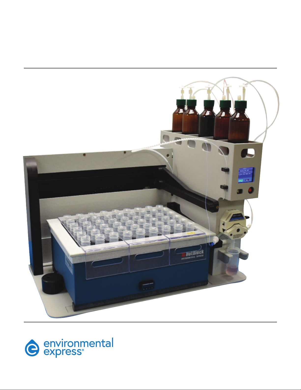
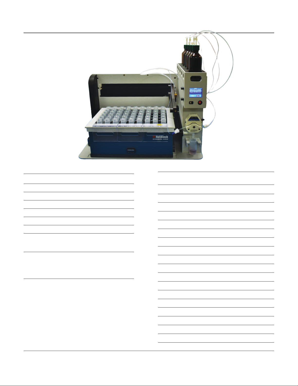
About Your Environmental Express AutoBlock®Fill Station
AutoBlock® Fill provides a safe, efcient method of adding digestion reagents to water, wastewater, soil, and sludge samples
for metals analysis. The station works with any size of HotBlock®, HotBlock® Pro, and HotBlock® 200 metals digestion systems
to automate the most dangerous step of metals digestion—the reagent addition.
The station dispenses independently from up to ve reagent bottles. No need to swap out reagent bottles when switching
digestion methods—a ve-way valve setup provides easy switching between reagents. The reagents are dispensed by an
integrated Masterex® peristaltic pump accurate to ±2% volume (calibratable to any dispensing volume).
The AutoBlock® Fill can be programmed and controlled via the onboard touch screen or use the included software to connect
directly to a computer. The station features preprogrammed EPA methods or the user can create customized programs.
Users should be aware of potential dangers from heating certain types of compounds. Such hazards may include explosion or
the release of toxic or ammable gases. The AutoBlock® Fill is designed to t in a fume hood.
Denitions/Markings
Each AutoBlock® Fill and/or HotBlock® product displays certain markings and symbols. All personnel working with the
AutoBlock® Fill and/or HotBlock® should have an understanding of the following symbols and denitions:
• V = voltage
• ~ = alternating current
• Hz = frequency
• A = amperes
This symbol means Caution
Hot Surface. The surface of the
HotBlock® may be too hot to
safely touch with bare hands.
This symbol means
Read and become familiar
with instructions before
operation of instrument.
Installation of your AutoBlock® Fill Station
1. The AutoBlock® Fill requires some assembly prior to operation. A video showing how to perform the assembly is located
on the AutoBlock® Fill product page.
2. The top section of foam packaging contains the horizontal brace, the HotBlock® rails, and the vertical brace. The
bottom section of foam packaging contains the tower, base plate, XY arm assembly, and power cord and tubing. A bag
of hardware to connect all the pieces together is also included.
3. Attach the tower to the base plate. Set the base plate on a secure at surface with the cam lock lever on the left side.
This will orient the base with the attached brace rail to the right, the wider track slot in the front, and the narrower
track slot towards the back. The far-right side will have an outline of the tower with six screw holes. The tower should
be oriented with the peristaltic pump to the front, the drain trench on the left, and the ve-way valve on the right. Use
six (6) #0.25-20 x 0.75 Phillips head screws. This step and the next one are best accomplished by laying the tower on its
back and having the bottom panel facing you.
4. Attach the vertical brace to the bottom panel at the left rear corner. The rounded end will be up in the air and the at
end will be attached to the panel. The notched side will be at the bottom facing the rear. Use two (2) #0.25-20 x 0.75
Phillips head screws.
5. Remove the side panel from the right side of the tower. You will need a Phillips head screwdriver to remove the screws.
Be sure to note which screws came from which holes. The shorter screws must go back in their specic holes to assure
proper t. Set the panel aside.

+1.800.343.5319 or +1.843.881.6560 envexp.com Environmental Express • 5
AutoBlock® Fill: Operation and Instruction Manual Installation, Safety & Maintenance
6. Attach the horizontal brace to the bottom panel, vertical brace, and tower. The open end of the horizontal brace will
t in the notch on the bottom of the vertical brace. The closed end of the horizontal brace will t up against the side
of the tower. Use ve (5) #10-25 x 0.375 Phillips head screws to secure the bottom of the horizontal brace. Use three (3)
#10-25 x 0.375 Phillips head screws with nuts to attach the horizontal brace to the tower. Make sure the nut is on the
inside of the tower. Use two (2) #10-25 x 0.375 Phillips head screws to attach the horizontal brace to the vertical brace.
Leave the middle spot empty for one (1) #0.25-20 x 0.75 Phillips head screw when attaching the XY arm assembly.
7. Remove the XY arm assembly from the box and set in place behind the unit.
8. Remove the back cover from the XY arm assembly. There are four (4) #10-24 x 0.375 Phillips head screws holding it in
place; two on each side.
9. Attach the XY arm assembly to the frame. Use ten (10) #0.25-20 x 0.75 Phillips head screws to attach the XY arm
assembly from the back. Use one (1) #0.25-20 x 0.25 screw inside the tower at the top.
10. Locate the two loose cable ends on the left side of the XY arm assembly and feed one through each of the two large
access holes in the back of the tower. The X motor cable coming from the far-left side of the assembly should be
inserted in the top hole. The Y motor cable runs inside along the length of the assembly and should be inserted in the
bottom hole.
11. Attach the X and Y motor cables to the top two cables inside the tower; X to the top position and Y to the second
position. The cables screw together and will be secure when you feel a physical click to lock them in place.
12. Attach the valve cables from the tower to the side panel. The cables are numbered near the connectors to match the
correct ones together.
13. Replace the side panel and back cover to the appropriate parts of the unit. Make sure to place the shorter screws on
the side panel in the appropriate positions. Snap the caps in place over the side panel screws.
14. Locate the wire support screws on the front left side of the tower and loosen them several full turns. There is no need
to remove them from the brackets. Insert the long end of the support wire (thicker solid piece) from the spiral-wrapped
assembly into the support brackets. Tighten the screws down to hold the wire in place.
15. Loosen the retaining screw on the side of the moving XY carriage, near the dispensing tip. Insert the other end of the
support wire and tighten the screw to hold the wire securely in place.
16. Loosen the ange nut above the dispensing tip on the XY carriage. Insert the delivery tube into the ange nut and
through the probe until it is ush with the end. Tighten the ange nut but do not clamp it down fully to pinch the
tubing.
17. Lift the locking lever of the peristaltic pump on the front of the tower. Insert the peristaltic pump tubing assembly
in the pump with the blue connector on the left side. Ensure that the pump tubing rests in between the clamps in
the ends of the locking lever prior to securing it in place. The tubing on the right side of the pump tubing assembly
attaches to the center port of the 5-way valve on the right side of the tower.
18. Attach the loose end of the delivery tubing to the left side of the pump tubing assembly. Insert the 100-mL vessel
(# SC490) in the waste container holder underneath the peristaltic pump on the front of the tower.

+1.800.343.5319 or +1.843.881.6560 envexp.com Environmental Express • 6
AutoBlock® Fill: Operation and Instruction Manual Installation, Safety & Maintenance
19. For each digestion reagent bottle, you will need to cut a piece of tubing from the included coil. Use an empty bottle
as a guide in determining the correct length. Insert one end of the tubing into the bottle cap and attach it to an
empty bottle. Slide the tube far enough into the bottle so that the end of the tubing is near the bottom of the bottle.
Do not put the tubing ush against the bottom of the container as it will not be able to draw liquid in an efcient
manner. Run the tubing in a gradual bend to the 5-way valve. Make sure there are no kinks in the tubing to restrict
ow. Use a ferrule and angeless nut to secure the tubing into one of the numbered ports in the 5-way valve. Repeat
for as many digestion reagents are desired.
Note: The bottle with DI water must always be connected to port #1.
20. Attach the 5-pin connector from the power block to the back-right corner of the AutoBlock® Fill.
Installation of a HotBlock® in the AutoBlock® Fill Station
1. If using a new HotBlock®, remove the metal screws from the bottom plate of the unit. Attach the appropriate size
rails to the bottom of the HotBlock® using the hex head screws included with the unit. An appropriate hex head
driver is also included with the AutoBlock® Fill. The rails should run from side to side on the HotBlock®. If using a
previously purchased HotBlock®, remove the PVC screws and rubber feet from the bottom of the unit. Attach the rails
as described above.
2. Adjust the locking cam lever to accommodate the size of the HotBlock® you are using. Slide it to the right for a
square block and to the left for a rectangular block. Tighten it down after adjustment.
3. Place the HotBlock® on the bottom plate of the AutoBlock® Fill with the controller facing front. Insert the power cord
through the slot in the back panel of the AutoBlock® Fill.
4. Slide the HotBlock® towards the back panel of the unit until the rails slide in place in the appropriate slots on the
base plate.
5. Slide the HotBlock® towards the tower until it is ush against the brace beside the tower.
6. Lock the cam lever in place against the side of the HotBlock®. It should be held securely in place and not move in
any direction. The HotBlock® is now ready for positional calibration.
Note: See the “Using the AutoBlock® Fill Software on a PC” section for instructions on how to perform this calibration.
Installation Requirements
If digestions are to be performed on a HotBlock® installed in the AutoBlock® Fill station, make sure to locate the entire
system under a fume hood with a minimum face velocity of 100 fpm, and allow a minimum of 2” of space on all sides. The
following environmental conditions should be observed:
• Ambient temperature range: 5–45°C
• Ambient relative humidity: 0–100%RH
• Altitude: sea level to 2500 meters
HotBlock® units are rated as Pollution Degree 2 and Installation Category 2.

+1.800.343.5319 or +1.843.881.6560 envexp.com Environmental Express • 7
AutoBlock® Fill: Operation and Instruction Manual Installation, Safety & Maintenance
Electrical Requirements
• Required Voltage 120/240 volts, ~50/60 Hz, Current – 10 A.
• Power should not vary greater than ±10%. Connecting to the power supply must be done with the supplied power cord.
• For safety reasons, a separate power receptacle should be provided for any HotBlock® installed in the unit. Do not use
extension cords or outlet adaptors. Make certain that power outlets are earth-grounded at the grounding pin.
Potential Hazards
The AutoBlock®Fill should only be operated by properly trained personnel using standard laboratory safety practices.
• The AutoBlock® Fill has moving parts which can pinch extremities or entangle loose hair or clothing.
• Use extreme caution when operating any attached HotBlock® digestion block. Plastic and graphite surfaces of the blocks may
be too hot to safely touch with bare hands.
• All components contain electrical circuits and devices and compounds operating at dangerous voltages.
Contact with these circuits, devices and components can cause serious injury or painful electric shock.
• Proper grounding is essential to avoid a potentially serious electric shock hazard. Ensure that there is an internal ground
connection between the metal base of the system and the 3-pin earth-grounded receptacle.
• For safety reasons, a separate power outlet receptacle should be provided for the AutoBlock ® Fill and any attached HotBlock®.
Do not use extension cords or outlet adaptors. Make certain each power outlet is earth-grounded at the grounding pin.
• Power requirements for individual blocks may be found on our website.
• Application of the wrong supply voltage can create a re hazard and a potentially serious shock hazard, and could seriously
damage the system. See specications for individual components.
• Users should be aware of potential dangers from heating certain types of compounds. Such dangers may include the
release of toxic or ammable gases or explosion.
Maintenance
• Any service inquiries should be directed to the Environmental Express Technical Service Department at +1.800.745.8218 or
+1.843.881.6560.
• After each use, clean exterior surfaces with a damp sponge to remove acid residue.
• For acid spills, sponge with a diluted solution of sodium bicarbonate followed by distilled water. Acid that is spilled
directly into the digestion wells should be neutralized and removed.
• Before using any cleaning or decontamination methods except those recommended, check with Environmental Express
to conrm the proposed method will not damage your AutoBlock® Fill and/or HotBlock®.
• Avoid excessive spills; as liquid allowed to overow into the AutoBlock® Fill and/or HotBlock® casing can seriously damage
electronic components.
• Monitor the waste receptacle during use to ensure the rinses do not exceed the capacity of the 100-mL waste vessel.

+1.800.343.5319 or +1.843.881.6560 envexp.com Environmental Express • 8
AutoBlock® Fill: Operation and Instruction Manual Operation
Operation Using the AutoBlock® Fill Software and Onboard Touch Screen
The AutoBlock® Fill can be run using either the software on a connected PC (for full control) or via the onboard touch screen
(for routine, daily tasks). After initial calibrations and method development are completed, the only required function for
connection to a PC is for regular pump volume calibration/verication. The software download and a video showing how to
use the AutoBlock® Fill software are available on the AutoBlock® Fill product page.
Using the AutoBlock® Fill Software on a PC
The AutoBlock® Fill software consists of a primary working screen with tabs along the left side of the display. The tabs allow
you to switch between functional screens and alert you to unsaved information or connection issues in the software.
1. Home Screen – The home screen provides an image of the AutoBlock® Fill and a
functional link to the Environmental Express website.
2. Communications Screen – This is where you will set up the serial ports for the
USB connection between the PC and the instrument. The software should connect
automatically once the USB cable is in place, however the rst time connecting may
require manual connection. Select the drop-down menu titled “Serial Port”. It defaults
to “Autodetect” and will need to be changed to whichever port is populated in the
menu. Then click the large button at the top labeled “Open Communications”. The
software will then connect and indicate that communication has been established.
1
2
3
4
5
6
7
8
9
10

+1.800.343.5319 or +1.843.881.6560 envexp.com Environmental Express • 9
AutoBlock® Fill: Operation and Instruction Manual Operation
3. HotBlock® Screen – This screen is used to calibrate the position of the HotBlock® and
check pump volumes. To calibrate the HotBlock® position, you must rst choose the
block type from the drop-down menu. Blocks are listed by the Environmental Express
part number (e.g. SC154) as well as the well conguration (e.g. 9x6). If you are unsure of
the part number, choose any option that has the correct well conguration. Once you
make a selection, a map of the wells will appear onscreen. If you select the “Custom”
option, you will need to specify the number of wells in each row and column. The cups’
positions are labeled in rows by number and columns by letter. You will calibrate on
the front left corner cup (always labeled “A1”) and the back right corner cup.
Click the “Calibrate” button on the row for “Location of Cup A1”. The button will turn
red and the dispensing probe will move to a location close to where the A1 cup should
be. Use the “Jog” arrows to position the arm so that the dispensing tip is centered above
the A1 cup. The magnitude of the motion from the “Jog” arrows can be adjusted to
smaller distances, down to 0.1 mm, by changing the eld value. You can use the
“Dispense” button to verify the position. If you anticipate using the disposable reux
caps, we recommend having one in position over the cup being calibrated.
Click the same “Calibrate” button as before. The button will change color again and the
position will be saved to the unit. Repeat these steps for the location of the cup in the
opposite corner. Once that is completed, click the “Save Block to ABFill” button. If you
have not saved the block calibration to the unit, a red asterisk [*] will appear on the tab
to alert you of unsaved changes.
4. Pump Calibration Screen – This screen allows you to adjust the pump to account for
changes in the pump tubing. The positions of the cups used to check the calibration are
xed but the volume used can be adjusted to something close to the standard amount
of liquid being dispensed. Place a preweighed empty cup in each red shaded well as
indicated on the map of the block. Change the amount listed in Step 1 to the desired
calibration amount; 2 mL is the default value. Click the “Dispense” button to begin the
procedure. The unit will then dispense the indicated amount into each of the cups.
Weigh the cups and determine the amount of water dispensed by the increase in mass.
Average the values and enter in the eld in Step 2. Click the “Update” button and the
software will automatically calculate the Calibration Factor to update in the eld at the
top of the screen. Repeat the calibration steps until the value stabilizes within a margin
of error acceptable for your laboratory.
Note: Environmental Express recommends checking this value at least weekly and
possibly more often depending on the use in your laboratory. We also recommend
changing the peristaltic pump tubing at least monthly.

+1.800.343.5319 or +1.843.881.6560 envexp.com Environmental Express • 10
AutoBlock® Fill: Operation and Instruction Manual Operation
5. Methods Screen – The methods screen allows you to develop programs for dispensing
of digestion reagents as well as conguration of the digestion reagents loaded onto the
unit. Many of the common digestion methods from 40CFR are already preprogrammed
in the software. You may edit an existing method or create a new method from scratch.
The steps available in a method are Dispense, Hold, and Prompt. Dispense allows
you to select a digestion reagent from those that are assigned and specify how much
volume of it you wish to add to each cup. Hold will set a countdown timer for the time
specied (in minutes) and wait until the timer expires before proceeding to the next
step. Prompt will complete the step and then display a custom message that requires
user acknowledgement prior to continuing.
The default reagents available for selection in the assignment screen are water (which
must always be assigned to port #1), HCl, HNO2, H2O2, and H2SO4. If you wish to use a
reagent besides one of these, select “None” for that port, highlight the text, and type in
the reagent name you wish to use. That reagent will then be an option to choose in the
“Dispense” command.
You must click the button “Save Methods to ABFill” in order to be able to run that
method in a sequence. If you wish to save the method to the PC directory, you must
click “Export Method”. If you have information on the Methods Screen that has not
been saved, it will display a red exclamation mark [!] to alert you.
6. Sequences Screen – This screen will be the day-to-day operations screen. To set a
sequence, you choose a method, choose which cups you wish to use, and give the
sequence a name. If using the PC to control the unit, you can start the sequence by
clicking the “Run Sequence Button”. If the touch-screen controller will be used to run
the sequences, you must click “Save Sequences to ABFill” in order to have them
available.
For routine operation, it is best to create a sequence using your most common
digestion method with no cups selected. Make sure that the “Cup Selection” box is
checked and save the sequence to the unit. This will allow you to ll in the cups needed
for digestion with each batch that you run. You can save multiple sequences to the unit.
When selecting cups, you may choose individual wells by clicking each one, entire rows
by selecting the appropriate letter, entire columns by selecting the appropriate number,
or the entire block by selecting “All” at the bottom left corner of the block map.
The tab will show a red asterisk [*] if there is unsaved information in the sequences
screen.
7. Run Log Screen – If you have checked the “Audit” box on a sequence, the unit will save
basic run information for the sequence including start date/time, operator ID, Batch ID,
sequence name, method used, selected wells, reagents assigned, and end time. The log
must be loaded from the unit and then saved to the PC in order to retain the records.
8. Advanced/Service Screen – This screen should only be used under the direction of
representatives from Environmental Express when troubleshooting the unit.

+1.800.343.5319 or +1.843.881.6560 envexp.com Environmental Express • 11
AutoBlock® Fill: Operation and Instruction Manual Operation
9. Maintenance/Supplies Screen – This screen contains part numbers and ordering
information for common consumable items related to the AutoBlock® Fill.
10. Help Screen – Contains contact information for technical support, links to the
manual, and links to support videos.
Using the Onboard Touch-Screen Controller
The onboard touch screen is intended for use in routine day-to-day operations of the AutoBlock® Fill. It is functional without a PC
being connected to the unit. The touch screen saves a copy of the sequences and methods that have been downloaded to it from
the PC software.
When using the touch screen, the user may cycle through all sequences that have
been saved to the unit. When going through the available sequences the screen
will display the method that has been assigned to that sequence, any cups that are
selected, and the reagents being used.
After selecting the desired sequence, it will display the block size and the volume
needed for each digestion reagent in use for that sequence. The user should verify
that the information is correct and that the appropriate volumes are available before
proceeding.
The next screen shows a map of the block with the selected cups to be lled. The user
will select “OK” or “Adjust Cups” depending on how the sequence is designed.

+1.800.343.5319 or +1.843.881.6560 envexp.com Environmental Express • 12
AutoBlock® Fill: Operation and Instruction Manual Operation
Adjusting the selected cups is done in a similar manner to using the PC software;
individually, in rows, in columns, or the entire block. Press “OK” after the correct cups
have been assigned.
It will then ask if you are ready to start the run. Press “Yes” to begin or “Cancel” to
return to the main menu.
+1.800.343.5319 or +1.843.881.6560 envexp.com Environmental Express • 13
AutoBlock® Fill: Operation and Instruction Manual Parts & Supplies
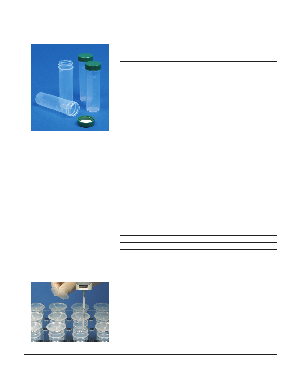
Polypropylene Disposable Screw-cap Digestion Cups
Eliminate Transfer Steps.
• Certied for low metals background and EPA approved†for digestions
• Volume certied
These carefully engineered digestion vessels provide premium performance in your
HotBlock®systems. Cups are molded of claried homopolymer polypropylene, providing
a higher working temperature (to 130C) and greater chemical resistance than commonly
used co-polymer polypropylene.
Accurate, molded-in graduations allow analysts to easily reproduce volumes to within
0.5%. Vessels serve as graduated cylinders, as well as storage containers. After digestion
is complete, the sample can be brought to volume and capped for storage, eliminating
time-consuming transfer steps. The result is a “one-cup” system that greatly reduces labor
and costs associated with metals preparation.
Screw caps are available with polyethylene-faced foam liners for a leak-proof seal (green
and white caps only) or as a plug-style closure (natural caps only).
Each box of cups comes with a Certicate of volume accuracy and a Certicate of Analysis
for 68 trace metals—only metals-free materials come in contact with your sample. Both
the Ultimate Cup (UC) and the Ultimate Clean Cup (UCC) vessels have been redesigned
for increased durability, stability, and a tighter seal. In addition, the Ultimate Clean Cup
comes in packaging to ensure ready-to-use arrival and is further trace-metal analysis
certied to parts-per-billion and parts-per-trillion levels.
†Environmental Express digestion cups are approved for, but not limited to, EPA Methods 3005, 3010,
3050B, 200.2, 200.7, 200.8, 7470A, 7471A, 245.1, and 245.7.
Total
Description Capacity Graduations Quantity Item #
15mL Cup (clear cap, no liner) 18mL to 15mL 1000 SC415
100mL Cup (white cap, liner) 125mL to 100mL 225 SC490
50mL Ultimate Cup (green cap, liner) 68mL to 50mL 500 UC475-GN
50mL Ultimate Cup (white cap, liner) 68mL to 50mL 500 UC475-W
50mL Ultimate Cup 68mL to 50mL 500 UC475-NL
(natural cap, no liner)
50mL Ultimate Clean Cup 68mL To 50mL 150 UCC000-50
(natural cap, no liner)
Ribbed Watch Glasses allow partial reux during digestion.
Ribbed watch glasses are available to t all Environmental Express digestion vessels.
Polypropylene construction is naturally free of contaminants. Watch glasses have a center
stem to aid in handling and decrease the potential for contamination.
Description For Digestion Cup Quantity Item #
19.5mm Watch Glass 15mL 1000 SC417
44mm Watch Glass 50mL 1000 SC505
52mm Watch Glass 100mL 500 SC610
For a complete list of consumables and
accessories, visit the Metals Digestions
section of our website.

+1.800.343.5319 or +1.843.881.6560 envexp.com Environmental Express • 14
AutoBlock® Fill: Operation and Instruction Manual EPA Method 200.2, Revision 2.8
1.0 Scope and Application
1.1 The following procedures have been written as an aid to EPA digestion
procedure 200.2 for use with the Environmental Express HotBlock. EPA
Method 200.2 is for the determination of total recoverable analytes in
groundwater, surface water, drinking water, wastewater and (with the
exception of silica) in solid samples such as sediment, sludge and soil.
Use EPA Method 200.2 for reference while following the sample preparation
steps outlined below. A complete list of elements appropriate for analysis is
included in EPA Method 200.2. Analysis can be performed by ame atomic
absorption, GF/AA, ICP and ICP-MS.
2.0 Apparatus and Materials
2.1 HotBlock for Metals Digestions — Item # C6002, SC100, SC150*, SC151*,
SC154, SC196, SC2015, SC2050, or SC2100*
2.2 Polypropylene Digestion Vessels — 50mL, 100mL, or 15mL
2.3 Ribbed Watch Glasses or Reux Caps, appropriately sized for vessel capacity
2.4 FilterMate — Item # SC0401 (or appropriate FilterMate® or FlipMate®) for
sample ltration if necessary
*Note: For all procedures, when using the block with the SC490 digestion vials with
a 100mL sample, double the volume of all reagents and acids added.
3.0 Procedure, Aqueous Sample Preparation
3.1 Mix sample thoroughly to achieve homogeneity. For each digestion
procedure, transfer a 50mL sample (or appropriate volume for your lab)
into the polypropylene digestion vessel. For best results, weigh the sample
directly in the vessel on a tared balance.
3.2 Add 1mL (1:1) HNO3and 0.5mL (1:1) HCl, then swirl. Heat the sample in the
HotBlock at 95°C for 2.5 hours without boiling. Place a ribbed watch glass
(SC505) on top of the digestion vessel.
Note: When using a watch glass, adjust the control point temperature of the HotBlock so
that a 50mL, 5% acid solution is heated to 85°C BEFORE placing the watch glass over the
sample. Laboratory tests have proven that the addition of the ribbed watch glass will add
approximately 10°C to the sample temperature, bringing the sample temperature up to 95°C.
3.3 Using the polycarbonate transfer racks, remove samples from the HotBlock
and allow them to cool.
3.4 After cooling, dilute samples to 50mL with DI Water.
3.5 If necessary, lter with SC0401 (or appropriate FilterMate® or FlipMate®)
to remove insoluble material.
Note: The ltration step should be performed slowly with little pressure placed on the
plunger. If excessive back pressure occurs, stop ltration and allow sediments to “settle out”.
Applying pressure to the plunger may cause sample “blow through” allowing sediment to
pass through the lter into the digestate.
Adaptation for EPA Method 200.2, Revision 2.8 for use with the
Environmental Express HotBlock® Digestion System Revised 12.13

+1.800.343.5319 or +1.843.881.6560 envexp.com Environmental Express • 15
AutoBlock® Fill: Operation and Instruction Manual EPA Method 200.2, Revision 2.8
4.0 Procedure, Solids Sample Preparation
4.1 Sieve a dried sample using a 5-mesh polypropylene sieve and grind in a
mortar and pestle. Weigh a representative sample of 0.5 ±0.01g into a
digestion vessel.
4.2 Add 2mL of (1+1) HNO3and 5mL of (1+4) HCl. Cover with a ribbed watch
glass (SC505) or reux cap (SC506),and place in the HotBlock at 95°C.
4.3 Heat sample for 30 minutes.
4.4 (Optional) Although step 3 is the nal heating step for EPA Method 200.2,
if the sample is suspected of having a high concentration of organic
compounds, it is recommend to complete this step:
Add 2mL of 30% H2O2to the well-cooled sample. Allow the exothermic
reaction to occur (approximately 10 minutes) and place the sample back
in the HotBlock at a temperature of 10° less than the original set point for
an additional 30 minutes. The reaction with the H2O2raises the sample
temperature. Boiling should not occur if the temperature of the HotBlock
is lowered.
Note: H2O2helps aid in the breakdown of high organic compounds in the sample thus
creating a more complete digestion.
4.5 Using the polycarbonate transfer racks, remove samples from the HotBlock
and allow them to cool completely.
4.6 Bring sample volume to 50mL with DI water.
4.7 If necessary, lter with SC0401 (or appropriate FilterMate® or FlipMate®)
to remove insoluble material.
Note: The ltration step should be performed slowly with little pressure placed on the
plunger. If excessive back pressure occurs, stop ltration and allow sediments to
“settle out”. Applying pressure to the plunger may cause sample “blow through” allowing
sediment to pass through the lter into the digestate.
All QC samples, concentration limitations, elemental lists and reagent specications
are addressed in depth in EPA Method 200.2. Safety concerns are also part of the full
method. Follow the instructions listed in EPA Method 200.2. These steps should only
be used as a guide to help improve the performance of your HotBlock.

+1.800.343.5319 or +1.843.881.6560 envexp.com Environmental Express • 16
AutoBlock® Fill: Operation and Instruction Manual EPA Method 200.7, Revision 4.4
1.0 Scope and Application
1.1 The following procedures have been written as an aid to EPA digestion
procedure 200.7 for use with the Environmental Express HotBlock. EPA
Method 200.7 is for the determination of total recoverable analytes in
groundwater, surface water, drinking water, wastewater, and (with the
exception of silica) in solid samples such as sediment, sludge and soil.
Use EPA Method 200.7 for reference while following the sample preparation
steps outlined below. A complete list of elements appropriate for analysis is
included in EPA Method 200.7. Analysis can be performed by ICP.
2.0 Apparatus and Materials
2.1 HotBlock for Metals Digestions — Item # C6002, SC100, SC150*, SC151*,
SC154, SC196, SC2015, SC2050, or SC2100*
2.2 Polypropylene Digestion Vessels — 50mL, 100mL, or 15mL
2.3 Ribbed Watch Glasses or Reux Caps, appropriately sized for vessel capacity
2.4 FilterMate — Item # SC0401 (or appropriate FilterMate® or FlipMate®) for
sample ltration if necessary
*Note: For all procedures, when using the block with the SC490 digestion vials with
a 100mL sample, double the volume of all reagents and acids added.
3.0 Procedure, Total Recoverable Elements, Aqueous Sample
(EPA Method 200.7, Paragraph 11.2)
3.1 Mix sample thoroughly to achieve homogeneity. For each digestion
procedure, transfer a 50mL sample (or appropriate volume for your lab)
into the polypropylene digestion vessel. For best results, weigh the sample
directly in the vessel on a tared balance.
3.2 Add 1mL 1:1 HNO3and 0.5mL 1:1 HCl and swirl. Heat in the HotBlock at a
sample temperature of 85°C and evaporate to about 10mL taking care that
the cup does not go dry. This will take approximately 2 hours.
3.3 Cover the vessel with a disposable watch glass (Item # SC505) and reux an
additional 30 minutes.
Note: When using a watch glass, adjust the set point temperature of the HotBlock so
that a 50mL, 5% acid solution is heated to 85°C BEFORE placing the watch glass over the
sample. Laboratory tests have proven that the addition of the ribbed watch glass will add
approximately 10°C to the sample temperature, bringing the sample temperature up to 95°C.
3.4 Using the polycarbonate transfer racks, remove samples from the HotBlock
and allow them to cool. Bring samples up to volume with DI water.
3.5 If necessary, lter with SC0401 (or appropriate FilterMate® or FlipMate®) to
remove insoluble material.
Note: The ltration step should be performed slowly with little pressure placed on the
plunger. If excessive back pressure occurs stop ltration and allow sediments to
“settle out”. Applying pressure to the plunger may cause sample “blow through” allowing
sediment to pass through the lter into the digestate.
Adaptation for EPA Method 200.7, Revision 4.4 for use with the
Environmental Express HotBlock® Digestion System Revised 12.13

+1.800.343.5319 or +1.843.881.6560 envexp.com Environmental Express • 17
AutoBlock® Fill: Operation and Instruction Manual EPA Method 200.7, Revision 4.4
4.0 Procedure, Total Recoverable Elements, Solids Sample
(EPA Method 200.7, Paragraph 11.3)
4.1 For each digestion procedure, transfer 0.5g ± 0.01g of a dried sieved
sample into the 50mL polypropylene vessel.
4.2 Add 2.0mL (1:1) HNO3and 5mL (1:4) HCl and swirl. Cover the vessel with
a disposable watch glass (item # SC505) and reux an additional
30 minutes at a sample temperature of 85°C.
Note: When using a watch glass, adjust the set point temperature of the HotBlock so
that a 50mL, 5% acid solution is heated to 85°C BEFORE placing the watch glass over the
sample. Laboratory tests have proven that the addition of the ribbed watch glass will add
approximately 10°C to the sample temperature, bringing the sample temperature up to 95°C.
4.3 Allow to cool and bring to 50mL volume with DI water.
4.4 Filter with SC0401 (or appropriate FilterMate® or FlipMate®) to remove
insoluble material.
All QC samples, concentration limitations, elemental lists and reagent specications
are addressed in depth in EPA Method 200.7. Safety concerns are also part of the full
method. Follow the instructions listed in EPA Method 200.7. These steps should only
be used as a guide to help improve the performance of your HotBlock.

+1.800.343.5319 or +1.843.881.6560 envexp.com Environmental Express • 18
AutoBlock® Fill: Operation and Instruction Manual EPA Method 200.8
1.0 Scope and Application
1.1 The following procedures have been written as an aid to EPA digestion
procedure 200.8 for use with the Environmental Express HotBlock. EPA
Method 200.8 is for the determination of total recoverable analytes in
groundwater, surface water, drinking water, wastewater, and (with the
exception of silica) in solid samples such as sediment, sludge and soil. Use
EPA Method 200.8 for reference while following the sample preparation
steps outlined below. A complete list of elements appropriate for analysis is
included in EPA Method 200.8. Analysis can be performed by ICP-MS.
2.0 Apparatus and Materials
2.1 HotBlock for Metals Digestions — Item # C6002, SC100, SC150*, SC151*,
SC154, SC196, SC2015, SC2050, or SC2100*
2.2 Polypropylene Digestion Vessels — 50mL, 100mL, or 15mL
2.3 Ribbed Watch Glasses or Reux Caps, appropriately sized for vessel capacity
2.4 FilterMate — Item # SC0401 (or appropriate FilterMate® or FlipMate®) for
sample ltration if necessary
*Note: For all procedures, when using the block with the SC490 digestion vials with
a 100mL sample, double the volume of all reagents and acids added.
3.0 Procedure, Aqueous Sample Preparation -- Dissolved Analytes
(EPA Method 200.8, Paragraph 11.1)
3.1 For the determination of dissolved analytes in ground and surface waters,
pipet a 20mL or greater aliquot of ltered, acid-preserved sample into the
polypropylene digestion vessel.
3.2 Add an appropriate volume of (1+1) HNO3to adjust the acid concentration
of the aliquot to approximate a 1% (v/v) nitric acid solution. If the direct
addition procedure is being used, add internal standards, cap and mix.
Note: If a precipitate is formed during acidication, transport or storage the sample aliquot
must be treated using procedures for Total Recoverable Analytes.
4.0 Procedure, Aqueous Sample Preparation — Total Recoverable Analytes
(EPA Method 200.8, Paragraph 11.2)
Note: This section applies to water samples containing turbidity of greater than 1 NTU.
4.1 For each digestion procedure, transfer 50mL of well-mixed, unltered,
acid-preserved sample into the polypropylene digestion vessel.
4.2 Add 1.0mL (1+1) HNO3and 0.5mL of (1+1) HCl and swirl. Heat in the
HotBlock at a sample temperature of 85°C. The HotBlock set temperature
should be approximately 105°C. The temperature of a reference blank
should be tested to ensure correct temperature.
Adaptation for EPA Method 200.8, for use with the
Environmental Express HotBlock® Digestion System Revised 12.13
This manual suits for next models
1
Table of contents
Other enviromental express Laboratory Equipment manuals

Popular Laboratory Equipment manuals by other brands


Belden
Belden HIRSCHMANN RPI-P1-4PoE installation manual

Koehler
Koehler K1223 Series Operation and instruction manual

Globe Scientific
Globe Scientific GCM-12 quick start guide

Getinge
Getinge 86 SERIES Technical manual

CORNING
CORNING Everon 6000 user manual

Biocomp
Biocomp GRADIENT MASTER 108 operating manual


