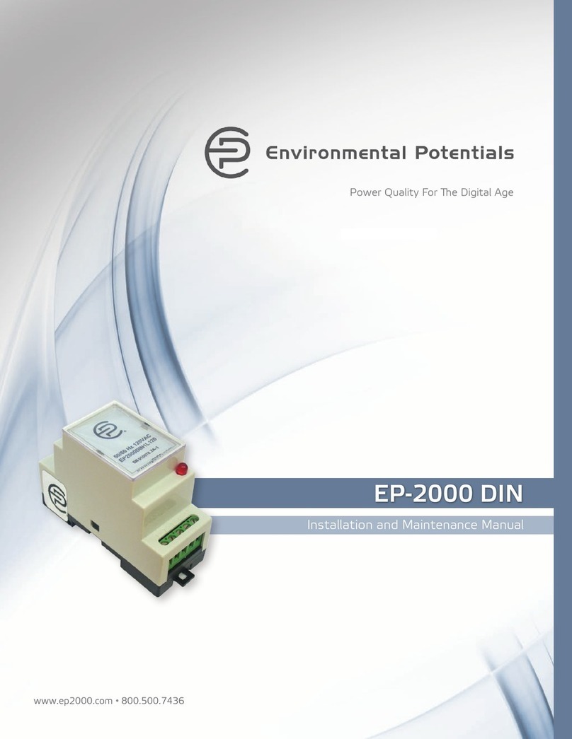
environmental potentials EP-2000 Series Manual

www.ep2000.com •800.500.7436
Power Quality For e Digital Age
Installation and Maintenance Manual
EP-2000 • EP-2050 • EP-2500
EP-2000 Series
Wall Mounted Waveform Corrector

EP-2000 Series INSTALLATION GUIDE 2
Mailing Address: 1802 N. Carson Street, Suite 108-2132, Carson City, NV 89701
FIVE YEAR WARRANTY
• Environmental Potentials will replace or repair any product from the EP-2000 product
line as long as it was not damaged during installation or damaged
from faulty installation.
• EP warranty registration card must be filled out and received by Environmental
Potentials within 15 days of installation.
• is warranty is for the repair or replacement of damaged EP products only.
Environmental Potentials accepts no liability, written or expressed, for the damage
that may have occurred to any other equipment; nor does Environmental Potentials
warranty cover any labor cost associated with replacement of such product.
Table of Contents
3 – Safety First
3 – Pre-Installation Preparations
4 – Voltage Ratings & Power Source Configurations
6 – Mounting
7 – Wiring
7 – Maintenance
7 – Servicing
EP-2000 Series Wall Mounted Waveform Corrector
Installation and Maintenance Manual


EP-2000 Series INSTALLATION GUIDE 4
Voltage Ratings & Power Source Configurations
Single Leg 1 Wire, 1 Neutral + Ground Installation
1. Connect white neutral to neutral bus bar.
2. Next connect black phase A to phase A of the 30 A breaker.
3. Last connect green ground to ground bus bar or panel. Ground is case ground only
and should NOT be connected to neutral bus bar.
SINGLE PHASE WYE
PRODUCTS
EP-2000
EP-2050
EP-2500
EP-2550
VOLTAGE
ID# MCOV
1L120 132 V
1L290 264 V
Single Phase Installation
1. Connect white neutral to neutral bus bar.
2. Next connect black phase A to phase A of the 30 A breaker.
3. en connect black phase B to phase B of 30 A breaker.
4. Last connect green ground to ground bus bar or panel. Ground is case ground only
and should NOT be connected to neutral bus bar.
TWO PHASE WYE
PRODUCTS
EP-2000
EP-2050
EP-2500
EP-2550
VOLTAGE
ID# MCOV
1S240 132 V
ree Phase Wye Installation
1. Connect white neutral to neutral bus bar.
2. Next connect black phase A to phase A of the 30 A breaker.
3. en connect black phase B to phase B of 30 A breaker.
4. en connect black phase C to phase C of 30 A breaker.
5. Last connect green ground to ground bus bar or panel. Ground is case ground only
and should NOT be connected to neutral bus bar.
THREE PHASE WYE
PRODUCTS
EP-2000
EP-2500
VOLTAGE
ID# MCOV
3Y208 132 V
3Y240 132V
3Y480 304V
3Y600 380V
L
N
Single Phase 1 Wire + Neutral
L1
N
L2
Split Phase 2 Wire + Neutral
L1
N
L2
L3
3 Phase Wye 3 Wire + Neutral
single leg 1 wire + 1 neutral
single phase, 2 wire + 1 neutral
3 phase Wye, 3 wire + 1 neutral

5
ree Phase Delta Installation
1. Connect black phase A to phase A of the 30 A breaker.
2. Next connect black phase B to phase B of 30 A breaker.
3. en connect black phase C to phase C of 30 A breaker.
4. Last connect green ground to ground bus bar or panel. Ground is case ground only
and should NOT be connected to neutral bus bar.
THREE PHASE DELTA
PRODUCTS
EP-2000
EP-2500
VOLTAGE
ID# MCOV
3D240 264V
3D480 528V
ree Phase High Leg Delta Installation
1. Connect black phase A to phase A of the 30 A breaker.
2. Next connect red phase B to phase B of the 30 A breaker.
WARNING: Please confirm that phase B is the HIGH LEG
3. en connect black phase C to phase C of the 30 A breaker.
4. Last connect green ground to ground bus bar or panel. Ground is case ground only
and should NOT be connected to neutral bus bar.
3 PHASE HL DELTA
PRODUCTS
EP-2000
EP-2500
VOLTAGE
ID# MCOV
3H240 132V
234V
L1
L2
L3
3 Phase Delta 3 Wire
L3
L1
L2
3 Phase Delta 3 Wire
N
3 phase delta 3 wire
3 phase delta 3 wire + neutral

EP-2000 Series INSTALLATION GUIDE 6
Mounting
For optimal performance, mount EP product as close to
electrical panel as possible. Longer wire increases inductance
in the system and the EP unit may not function properly.
Make sure the EP product is mounted in a dry and clean
environment. e EP unit can be mounted in any secure area
above, below, beside or inside the electrical panel.
For optimal performance:
• EP-2000 should be connected no more than 6 inches
from electrical panel.
• EP-2500 should be connected no more than 12 inches
from electrical panel.
Although internal mounting can be preferred mounting for
shorter lead lengths and optimal performance, it poses two
problems:
1. IEEE does not recommend internal mounting of
Waveform Corrector in the event of end of life
termination of the unit that may cause damage to the
internal distribution panel.
2. On internal installation the panel must be opened for
visual verification of units’ functional status.
Ensure you have considered all of these options before
attempting internal installation.
WARNING
• ALWAYS have a professional
electrician with proper safety
equipment perform installation.
• Any attempt to open unit voids
warranty.
!!
SIDE MOUNTING
EP units are designed for installation to ½ inch
panel knockout on side, top or bottom of panel.
Unit may also be secured with #8 self tapping or
wood screws.
INTERNAL MOUNTING
Ensure a minimum of 1 inch clearance to all
electrical surfaces before attempting an internal
mounting.

7
Wiring
1. Requires a dedicated 30 A circuit breaker to connect
Waveform Corrector to the electrical system.
2. Wire should be connected straight to the power
source. Avoid sharp bends and refrain from splicing
the wires as this will reduce the effectiveness of
the unit.
3. Do not twist wires.
NOTE: It is good electrical practice to tighten all of the
bolts in the electrical panel. Electrical leads should be
connected securely to prevent fire or electrical damage.
Maintenance
EP products do NOT require periodic maintenance. e
units have LED lights to provide visual indication of the
unit’s functional status. It is also good practice to inspect
the connections of the power supply wiring to the EP unit
monthly.
Servicing
EP units contain no serviceable parts and require no
adjustments. All EP products are designed to provide many
years of electrical protection without any need for servicing.
If the EP unit does malfunction, have a professional
electrician inspect the wire connections. If the problem
persists, contact your EP sales representative to discuss
obtaining a replacement unit.
WYE INSTALLATION
DELTA INSTALLATION
Line 1
Line 1
Line 2
Line 2
Line 3
Line 3
Neutral
Ground
Ground
This manual suits for next models
3
Table of contents
Other environmental potentials Power Distribution Unit manuals
