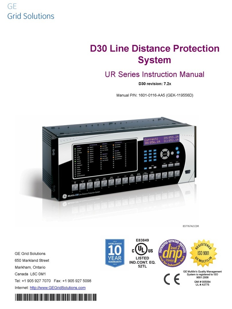
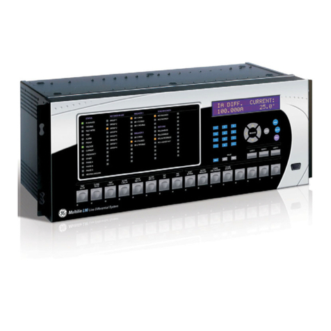
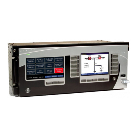
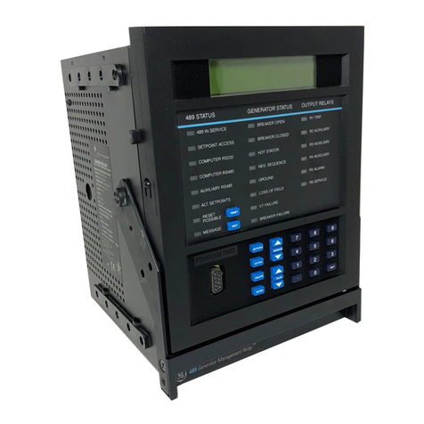
GE D90 Plus User manual

GE
Grid Solutions
Instruction Manual
Product version: 1.6x
GE publication code: 1601-9019-C4 (GEK-113258D)
D90Plus
Line Distance Protection System
1601-9019-C4
IISO 9001
G
N
E
I
L
M
I
U
T
L
T
E
S
I
R
G
E
E
D
R

Copyright © 2016 GE Multilin Inc. All rights reserved.
D90Plus Line Distance Protection System Instruction Manual for version 1.6x.
D90PlusController, EnerVista, EnerVista Launchpad, EnerVista URPlus Setup, FlexLogic,
Multilin, and GE Multilin are trademarks or registered trademarks of GE Multilin Inc.
The contents of this manual are the property of GE Multilin Inc. This documentation is
furnished on license and may not be reproduced in whole or in part without the permission
of GE Multilin. The content of this manual is for informational use only and is subject to
change without notice.
Part number: 1601-9019-C4 (October 2016)

D90PLUS LINE DISTANCE PROTECTION SYSTEM – INSTRUCTION MANUAL iii
D90Plus Line Distance Protection System
Table of contents
1 GETTING STARTED Important procedures ...................................................................................................1
Cautions and warnings................................................................................................................................1
Inspection checklist.......................................................................................................................................1
Introduction to the URPlus-series.................................................................................2
Hardware architecture ................................................................................................................................3
Firmware architecture .................................................................................................................................4
Communications overview ........................................................................................................................6
EnerVista software.........................................................................................................7
Software requirements................................................................................................................................8
Installing the EnerVista URPlus Setup software.................................................................................8
Software access........................................................................................................................................... 10
2PRODUCT
DESCRIPTION
Device overview............................................................................................................15
Front panel interface .................................................................................................................................16
Protection features.....................................................................................................................................17
Automation features..................................................................................................................................20
Equipment manager features ...............................................................................................................21
Metering and monitoring features...................................................................................................... 22
Digital fault recorder..................................................................................................................................23
Communications .........................................................................................................................................24
Order codes ...................................................................................................................24
Specifications................................................................................................................25
Protection specifications..........................................................................................................................25
Automation specifications ...................................................................................................................... 36
Equipment manager..................................................................................................................................37
Metering specifications ............................................................................................................................38
Digital fault recorder specifications....................................................................................................39
Front panel interface .................................................................................................................................40
Hardware specifications.......................................................................................................................... 41
Communications specifications ...........................................................................................................43
Test specifications.......................................................................................................................................43
Environmental specifications ................................................................................................................44
Approvals and certification.....................................................................................................................44
3 INSTALLATION Physical installation.....................................................................................................45

iv D90PLUS LINE DISTANCE PROTECTION SYSTEM – INSTRUCTION MANUAL
TABLE OF CONTENTS
Dimensions .....................................................................................................................................................45
Module withdrawal and insertion ........................................................................................................46
Rear terminal layout...................................................................................................................................47
Electrical installation...................................................................................................48
Typical wiring .................................................................................................................................................49
Dielectric strength .......................................................................................................................................50
Main processor module ............................................................................................................................50
Power supply module.................................................................................................................................52
AC modules.....................................................................................................................................................53
Contact inputs and outputs ....................................................................................................................55
4 INTERFACES Front panel overview ...................................................................................................61
Front panel interface operation............................................................................................................62
Metering menu..............................................................................................................................................63
Control menu .................................................................................................................................................63
Digital fault recorder menu.....................................................................................................................64
Equipment manager menu .....................................................................................................................66
Annunciator....................................................................................................................................................67
5 ENERVISTA
SOFTWARE SUITE
Introduction to EnerVista URPlus Setup ....................................................................71
Extended EnerVista URPlus Setup features ..............................................................71
Setting templates.........................................................................................................................................71
Securing and locking FlexLogic™ equations...................................................................................76
Settings file traceability.............................................................................................................................77
6 COMMUNICATIONS Communications overview .........................................................................................81
Network topology ........................................................................................................................................81
Network settings ..........................................................................................................84
Ethernet ports................................................................................................................................................84
TFTP protocol .................................................................................................................................................88
SNTP protocol ................................................................................................................................................89
Ethernet actual values...............................................................................................................................90
Modbus communications............................................................................................91
Modbus protocol ..........................................................................................................................................91
Modbus user map........................................................................................................................................92
DNP communications ..................................................................................................93
DNP protocol..................................................................................................................................................93
DNP user point list .......................................................................................................................................97
IEC 60870-5-104 communications ............................................................................98
IEC 60870-5-104 protocol settings......................................................................................................98
IEC 60870-5-104 point lists ..................................................................................................................100
IEC 60870-5-104 actual values ..........................................................................................................101
IEC 61850 communications ..................................................................................... 101
GSSE/GOOSE configuration..................................................................................................................101
IEC 61850 server configuration..........................................................................................................114
Logical node prefixes ..............................................................................................................................116
MMXU deadbands ....................................................................................................................................118
GGIO1 status configuration .................................................................................................................120
GGIO2 control configuration................................................................................................................121
GGIO4 analog configuration................................................................................................................122
Report control configuration ...............................................................................................................124
IEC 61850 actual values.........................................................................................................................125
FlexStates.................................................................................................................... 126

TABLE OF CONTENTS
D90PLUS LINE DISTANCE PROTECTION SYSTEM – INSTRUCTION MANUAL v
FlexState settings ..................................................................................................................................... 126
FlexState actual values.......................................................................................................................... 126
Real time clock........................................................................................................... 127
User-programmable self-tests ............................................................................... 129
Serial port ................................................................................................................... 130
Shared operands ....................................................................................................... 131
Shared communication operands.................................................................................................... 132
Communication logic operands ........................................................................................................ 133
7 PROTECTION Protection overview..................................................................................................135
Introduction to protection elements ............................................................................................... 135
Power system............................................................................................................. 137
Installation settings ................................................................................................................................. 137
AC input modules ..................................................................................................................................... 138
Power system frequency ...................................................................................................................... 143
About AC sources ..................................................................................................................................... 144
Grouped protection elements................................................................................. 148
Line pickup................................................................................................................................................... 148
Distance elements ................................................................................................................................... 152
Current elements...................................................................................................................................... 187
Voltage elements...................................................................................................................................... 223
Breaker failure ........................................................................................................................................... 233
Wattmetric zero-sequence directional ground fault............................................................... 244
Control elements ....................................................................................................... 248
Pilot schemes ............................................................................................................................................. 249
Setting group control.............................................................................................................................. 274
Trip output ................................................................................................................................................... 276
FlexMatrix..................................................................................................................................................... 281
VT fuse failure............................................................................................................................................. 284
Open pole detector.................................................................................................................................. 286
Autoreclose ................................................................................................................................................. 289
Underfrequency ........................................................................................................................................ 312
Overfrequency ........................................................................................................................................... 314
Breaker configuration ............................................................................................................................ 316
Breaker flashover ..................................................................................................................................... 323
Digital counters ......................................................................................................................................... 328
FlexCurves™ ............................................................................................................................................... 331
Protection inputs and outputs................................................................................ 335
Protection virtual inputs........................................................................................................................ 335
Protection virtual outputs..................................................................................................................... 337
Contact input and output default assignment........................................................................... 338
Contact input configuration................................................................................................................ 338
Contact outputs ........................................................................................................................................ 342
Shared operands ...................................................................................................................................... 343
Protection FlexLogic™ .............................................................................................. 345
Protection FlexLogic™ gates and operators ............................................................................... 348
FlexLogic™ rules ....................................................................................................................................... 349
Graphical programming interface ................................................................................................... 349
Protection FlexLogic™ equation editor.......................................................................................... 351
Protection FlexLogic™ timers ............................................................................................................. 352
Non-volatile latches ................................................................................................................................ 353
Protection FlexElements™.................................................................................................................... 354
Protection FlexLogic™ operands ...................................................................................................... 359

vi D90PLUS LINE DISTANCE PROTECTION SYSTEM – INSTRUCTION MANUAL
TABLE OF CONTENTS
8 AUTOMATION Automation controller overview............................................................................. 373
Input and output structure...................................................................................................................374
Breakers ...................................................................................................................... 375
Breaker control ..........................................................................................................................................375
Breaker interlocking.................................................................................................................................378
Disconnects ................................................................................................................ 380
Disconnect configuration......................................................................................................................380
Disconnect control ...................................................................................................................................385
Disconnect interlocking .........................................................................................................................388
Automation control................................................................................................... 390
Front panel status and control...........................................................................................................390
Local-remote control scheme.............................................................................................................392
Synchrocheck .............................................................................................................................................394
Selector switch...........................................................................................................................................399
Automation inputs and outputs ............................................................................. 405
Automation virtual inputs .....................................................................................................................405
Automation virtual outputs ..................................................................................................................407
Contact input and output default assignment ...........................................................................408
Contact input configuration.................................................................................................................409
Contact outputs.........................................................................................................................................413
Virtual analog outputs............................................................................................................................415
Shared operands.......................................................................................................................................415
Automation logic ....................................................................................................... 417
Automation operators ............................................................................................................................420
Automation logic equation editor .....................................................................................................424
Automation logic operands..................................................................................................................431
9EQUIPMENT
MANAGER
Overview of the equipment manager.................................................................... 435
Breaker management............................................................................................... 436
Circuit breaker arcing .............................................................................................................................436
Battery monitor ......................................................................................................... 439
Indications and wiring ............................................................................................................................439
Battery monitor settings........................................................................................................................440
Shared operands ....................................................................................................... 442
Shared equipment manager operands..........................................................................................443
Equipment manager operands ..........................................................................................................444
10 DIGITAL FAULT
RECORDER
Sequence of events recorder................................................................................... 447
Front panel operation .............................................................................................................................447
Fault report................................................................................................................. 448
Front panel indications...........................................................................................................................448
Fault report operation.............................................................................................................................449
Fault type determination.......................................................................................................................450
Fault location ..............................................................................................................................................450
Fault report settings ................................................................................................................................451
Transient recorder .................................................................................................... 454
Front panel indications...........................................................................................................................456
Transient recorder settings ..................................................................................................................457
Disturbance recorder ............................................................................................... 462
Front panel indications...........................................................................................................................464
Disturbance recorder settings ............................................................................................................465
Shared operands ....................................................................................................... 470
Shared digital fault recorder operands ..........................................................................................471

TABLE OF CONTENTS
D90PLUS LINE DISTANCE PROTECTION SYSTEM – INSTRUCTION MANUAL vii
11 METERING Metering source......................................................................................................... 473
Phasor measurement unit....................................................................................... 473
Phasor measurement unit configuration...................................................................................... 474
Phasor measurement unit calibration............................................................................................ 475
Phasor measurement unit communications............................................................................... 476
Phasor measurement unit triggering ............................................................................................. 479
Phasor measurement unit recording.............................................................................................. 488
Phasor measurement unit reporting over network ................................................................. 492
Phasor measurement unit one-shot............................................................................................... 493
Data logger................................................................................................................. 496
Data logger function configuration................................................................................................. 496
Data logger channel configuration.................................................................................................. 498
Shared operands ....................................................................................................... 500
Shared metering operands.................................................................................................................. 501
Metering logic operands ....................................................................................................................... 502
12 LOCAL INTERFACE Local interface overview.......................................................................................... 505
Annunciator panel..................................................................................................... 505
Annunciator operation........................................................................................................................... 505
Annunciator configuration................................................................................................................... 507
Mimic diagram editor ............................................................................................... 509
Dynamic symbols ..................................................................................................................................... 510
Static symbols............................................................................................................................................ 511
Metering blocks ......................................................................................................................................... 512
Text blocks................................................................................................................................................... 513
View modes................................................................................................................................................. 513
Pre-configured mimic diagrams ....................................................................................................... 514
User-programmable pushbuttons ......................................................................... 518
User-programmable pushbuttons settings ................................................................................. 519
13 SECURITY Password security .....................................................................................................523
Password security settings.................................................................................................................. 524
Password security operation .............................................................................................................. 526
EnerVista security management system.............................................................. 527
Enabling the security management system................................................................................ 527
Adding a new user ................................................................................................................................... 527
Modifying user privileges...................................................................................................................... 528
14 TESTING Test mode ................................................................................................................... 531
Force contact inputs............................................................................................................................... 531
Force contact outputs............................................................................................................................ 532
Self-tests ..................................................................................................................... 533
Self-test error messages....................................................................................................................... 534
15 THEORY OF
OPERATION
The D90Plus distance elements ............................................................................... 539
Distance element arming logic.......................................................................................................... 539
Distance element time domain algorithm.................................................................................... 540
Distance element frequency domain algorithm........................................................................ 540
Distance supervision............................................................................................................................... 541
Distance characteristics........................................................................................................................ 542
Memory polarization............................................................................................................................... 548
Distance elements analysis................................................................................................................. 549

viii D90PLUS LINE DISTANCE PROTECTION SYSTEM – INSTRUCTION MANUAL
TABLE OF CONTENTS
Phase distance applied to power transformers .................................................. 553
Example system with power transformers...................................................................................556
Ground directional overcurrent theory................................................................. 558
Ground directional overcurrent example ......................................................................................559
Series compensated lines ........................................................................................ 559
Memory polarized directional comparators.................................................................................560
Dynamic reach control...........................................................................................................................561
Single-pole tripping................................................................................................... 563
SLG fault scenario for single-pole tripping....................................................................................565
SLG fault evolving into an LLG fault scenario for single-pole tripping.............................566
Phase selection ..........................................................................................................................................567
Communications channels for pilot-aided schemes ...............................................................568
Permissive echo signaling.....................................................................................................................575
Pilot scheme and phase selector coordination ..........................................................................576
Cross-country fault example...............................................................................................................577
16 MAINTENANCE General maintenance ............................................................................................... 579
Back up and restore settings .................................................................................. 579
Back up settings ........................................................................................................................................579
Restore settings .........................................................................................................................................580
Upgrade software...................................................................................................... 580
Upgrade firmware ..................................................................................................... 581
Uninstall and clear files and data .......................................................................... 582
Repairs.........................................................................................................................582
Storage ........................................................................................................................ 582
Disposal....................................................................................................................... 583
17 APPENDIX Warranty..................................................................................................................... 585
Revision history ......................................................................................................... 585

D90PLUS LINE DISTANCE PROTECTION SYSTEM – INSTRUCTION MANUAL 1
D90Plus Line Distance Protection System
Chapter 1: Getting started
Getting started
Please read this section to help guide you through the initial setup of the D90Plus Line
Distance Protection System.
Important procedures
It is highly recommended that the following sections are reviewed before placing the
D90Plus in service.
Cautions and warnings
Before attempting to install or use the device, review all safety indicators in this document
to help prevent injury, equipment damage, or downtime.
The following safety and equipment symbols are used in this document.
DANGER
DANGER: Indicates a hazardous situation which, if not avoided, will result in death or serious
injury.
WARNING
IMPORTANT: Indicates a hazardous situation which, if not avoided, could result in death or serious
injury.
CAUTION
CAUTION: Indicates a hazardous situation which, if not avoided, could result in minor or
moderate injury.
NOTICE
FASTPATH: Indicates practices not related to personal injury.
Inspection checklist
Use the following procedure to unpack and inspect the D90Plus.
1. Open the system packaging and inspect the unit for physical damage.
2. View the rear nameplate and verify that the correct model has been ordered.
3. Ensure that the following items are included:
– Instruction Manual and Communications Guide (if ordered).

2D90
PLUS LINE DISTANCE PROTECTION SYSTEM – INSTRUCTION MANUAL
INTRODUCTION TO THE URPlus-SERIES CHAPTER 1: GETTING STARTED
– GE EnerVista CD (includes software and documentation).
4. For product information, instruction manual updates, and the latest software updates,
please visit the GE Multilin website at http://gegridsolutions.com/multilin.
5. If there is any noticeable physical damage, or any of the contents listed are missing,
please contact GE Multilin immediately.
GE Multilin contact information and call center for product support:
GE Grid Solutions
650 Markland Street
Markham, Ontario
Canada L6C 0M1
Worldwide telephone: +1 905 927 7070
Europe/Middle East/Africa telephone: +34 94 485 88 54
North America toll-free: 1 800 547 8629
Fax: +1 905 927 5098
E-mail: multilin.tech@ge.com
Website: http://gegridsolutions.com/multilin
Introduction to the URPlus-series
Historically, substation protection, control, and metering functions were performed with
electromechanical equipment. This first generation of equipment was gradually replaced
by analog electronic equipment, most of which emulated the single-function approach of
their electromechanical precursors. Both of these technologies required expensive cabling
and auxiliary equipment to produce functioning systems.
Recently, digital electronic equipment has begun to provide protection, control, and
metering functions. Initially, this equipment was either single function or had very limited
multi-function capability, and did not significantly reduce the cabling and auxiliary
equipment required. However, recent digital relays have become quite multi-functional,
reducing cabling and auxiliaries significantly. These devices also transfer data to central
control facilities and human-machine interfaces using electronic communications. The
functions performed by these products have become so broad that many users now prefer
the term IED (Intelligent Electronic Device).
It is obvious to station designers that the amount of cabling and auxiliary equipment
installed in stations can be even further reduced, to 20 to 70% of the levels common in
1990, to achieve large cost reductions. This requires placing even more functions within
the IEDs.
Users of power equipment are also interested in reducing cost by improving power quality
and personnel productivity, and as always, in increasing system reliability and efficiency.
These objectives are realized through software which is used to perform functions at both
the station and supervisory levels. The use of these systems is growing rapidly.
High speed communications are required to meet the data transfer rates required by
modern automatic control and monitoring systems. In the near future, very high speed
communications will be required to perform protection signaling with a performance
target response time for a command signal between two IEDs, from transmission to
reception, of less than 3 milliseconds. This has been established by the IEC 61850 standard.
IEDs with the capabilities outlined above will also provide significantly more power system
data than is presently available, enhance operations and maintenance, and permit the use
of adaptive system configuration for protection and control systems. This new generation
of equipment must also be easily incorporated into automation systems, at both the
station and enterprise levels. The GE Multilin Advanced Universal Protection System
(URPlus-series) has been developed to meet these goals.

CHAPTER 1: GETTING STARTED INTRODUCTION TO THE URPlus-SERIES
D90PLUS LINE DISTANCE PROTECTION SYSTEM – INSTRUCTION MANUAL 3
The D90Plus is the sub-cycle distance protection and advanced automation controller for
the URPlus-series platform.
Hardware architecture
The D90Plus is a microprocessor-based device. It has a modular design consisting of a
chassis containing discrete modules that interface over a common bus. Each module is
dedicated to a specific purpose. Several of the modules are required for basic operation of
the device, while others are optional.
The power supply module receives AC or DC power from an external supply and produces
conditioned 12 V DC power for all of the modules in the chassis. The power supply also
generates 48 V DC power for external contact wetting. The output contact indicating a
critical failure of the unit also resides on this module.
The AC module measures AC currents and voltages derived from CTs and VTs. These
signals are sampled and digitized and sent over the D90Plus bus to the CPU module for
further processing. A version is available that accepts nominal 5 A current and another
that accepts nominal 1 A current.
Input and output modules monitor digital (on and off) signals from external devices (field
contacts or other IEDs), control external devices such as breakers, and send digital signals
to other devices. Input and output modules are subdivided into protection inputs and
outputs and automation inputs and outputs, with several flavors of each type.
The CPU module contains the firmware for the D90Plus. The firmware contains the
algorithms required for the various functions provided by the device. The CPU receives
analog and digital data from the AC and input/output modules. The data is processed by
the CPU and resulting control actions are sent back to the input-output modules. The CPU
has one rear Ethernet port that is used for configuration and record retrieval and one rear
RS485 port supporting the Modbus and DNP protocols. The CPU also contains the IRIG-B
port required for clock synchronization.
The communications module is required for communicating with external devices over
Ethernet using the IEC 61850, DNP 3.0, or IEC60870-5-104 protocols. This module is also
required for peer-to-peer GSSE/GOOSE messaging. This module contains its own
microprocessor which is dedicated to handling communications tasks. It also contains two
redundant Ethernet ports. Each port supports 100Base-FX over multi-mode fiber and 10/
100Base-TX over twisted pair, with auto-negotiation. These ports may additionally be
configured for single IP or dual IP redundancy.
NOTE
NOTE: The D90Plus requires one power supply module, one CPU module, one AC module, and at
least one protection input/output module. Communications modules are optional.
The front panel interface consists of an annunciator display, a main display, and an
EnerVista USB port. The annunciator display collects alarm indications from the
D90Plus internal functions and presents them using a standard annunciator format. Alarms
and their corresponding messages are entirely user-configurable. The main display allows
the user to view metering data collected by the D90Plus. It also provides access to the
control functions via dedicated control pushbuttons. The USB port allows the user to
interface with the D90Plus using the EnerVista software running on a portable PC. The
D90Plus operates independently from the front panel interface.

4D90
PLUS LINE DISTANCE PROTECTION SYSTEM – INSTRUCTION MANUAL
INTRODUCTION TO THE URPlus-SERIES CHAPTER 1: GETTING STARTED
Figure 1: D90Plus block diagram
Figure 2: D90Plus hardware overview
Firmware architecture
The D90Plus is organized into six major functions.
•Protection.
• Automation.
• Metering.
$&'5
3URWHFWLRQ
$XWRPDWLRQ
(TXLSPHQWPDQDJHU
'LJLWDOIDXOWUHFRUGHU
0HWHULQJ
/RFDO+0,
&RQWDFWRXWSXWV
9LUWXDORXWSXWV
*226(
*66(
&RQWDFWLQSXWV
9LUWXDOLQSXWV
&7LQSXWV
97LQSXWV
*226(
*66(
+0,6&$'$ ,('
(QHU9LVWDVRIWZDUH
$&PRGXOHV
IDFLOLWDWHILHOG
XSJUDGHV
$QDORJ
PHDVXUHPHQW
RIFRQWDFWVWDWH
&RPPXQLFDWLRQV
PRGXOH
%DVH7
%DVH);
6LQJOH$&PRGXOHIRU
òEUHDNHUVFKHPH
6LQJOHJURXQGLQJ
VWXGIRUVLPSOLILHG
ZLULQJ
5XJJHGFKDVVLV
²&WR&
7ZRWLHUHGGDJJHUHG
WHUPLQDOEORFNVHDV\
DFFHVVWRORZHU
WHUPLQDOV
0DLQWHQDQFH
(WKHUQHWSRUW
6HSDUDWLRQEHWZHHQ
FRPPXQLFDWLRQVDQG
'&ZLULQJ
$&'5

CHAPTER 1: GETTING STARTED INTRODUCTION TO THE URPlus-SERIES
D90PLUS LINE DISTANCE PROTECTION SYSTEM – INSTRUCTION MANUAL 5
• Digital fault recorder (DFR).
• Equipment manager.
• Front panel interface (HMI).
These functions operate autonomously from one another. Each function has its own
configuration parameters and each generates it own output signals. All functions share
the hardware and the communications facilities within the device.
The protection function contains the necessary elements required to detect faults in the
power system and send tripping signals to isolate the fault. This will be the primary sub-
system for many users. The protection function also has its own dedicated FlexLogic™
engine which runs at the same scan rate as the protection (16 times per power system
cycle). Protection FlexLogic™ is used to create custom logic schemes for protection
purposes.
Automation is divided into two major sub-groupings: control schemes and automation
logic. Control schemes are hard-coded general purpose schemes responsible for
automatic control within the substation. These include breaker and disconnect switch
control, interlocking, and synchrocheck. Automation logic is intended for development of
custom or advanced automatic schemes in the case the user requires a level of
functionality beyond that found in the hard-coded schemes. Automation logic generally
requires a lower execution rate than protection logic but has greatly expanded
functionality and lines of logic.
The metering function generates a wide range of real-time power system measurements
including voltage, current, frequency, complex power, and energy. It also incorporates a
data logger that provides historical recording of selected metering quantities and includes
statistical (maximum, minimum, and average) and alarming capabilities. The metering
function also provides synchrophasor capabilities in accordance with IEEE C37.118-2005.
The digital fault recorder incorporates transient recorder, disturbance recorder and fault
report capabilities. The transient recorder is intended to capture short events such as a
fault at a high sampling rate (up to 256 samples per cycle). The disturbance recorder
captures longer events such as a power swing at a lower sampling rate. The channel
assignments and triggering of these features can be independently configured. The fault
report facility provides a comprehensive record of the key measurements associated with
an event including fault type, fault location, pre-fault and post-fault quantities, and
clearing time.
The equipment manager function monitors important parameters of the station battery
under normal operation and can be used to detect incipient failures.
Despite their logic separation, signals can be exchanged between these functions. For
instance, it is useful for the digital fault recorder to record the output of protection
functions. Consequently a fixed, pre-determined set of signals is available as inputs to
each function. These are illustrated in the following figure.
The D90Plus also includes shared operand functionality. Output signals from the various
functions can be assigned as shared operands available to all functions. These signals can
then be assigned as inputs within other functions.
For example, assume that the PHASE TOC1 OP protection FlexLogic™ operand is required as
a signal within the automation function. This signal would be assigned as a shared
operand. As such, the PHASE TOC1 OP operand would subsequently become available to the
automation function by appearing in the list of available operands.

6D90
PLUS LINE DISTANCE PROTECTION SYSTEM – INSTRUCTION MANUAL
INTRODUCTION TO THE URPlus-SERIES CHAPTER 1: GETTING STARTED
Figure 3: Functional architecture
Communications overview
The EnerVista URPlus Setup software can communicate with the relay through three ports:
the front panel USB port, the rear Ethernet port, and the rear RS485 port. Both rear ports
are located in slot D.
9LUWXDORXWSXWV
(OHPHQWV«
)OH[/RJLF
9LUWXDODQDORJV
'DWDORJJHU
V\QFKURSKDVRUV
3URWHFWLRQ
3URWHFWLRQDQDORJYDOXHV
)OH[$QDORJYDOXHV
3URWHFWLRQRSHUDQGV
9LUWXDOLQSXWV
6KDUHGRSHUDQGV
$XWRPDWLRQ
9LUWXDODQDORJYDOXHV
)OH[$QDORJYDOXHV (OHPHQWV«
$XWRPDWLRQORJLF
$XWRPDWLRQRSHUDQGV
9LUWXDOLQSXWV
6KDUHGRSHUDQGV
'LJLWDOIDXOWUHFRUGHU
)OH[$QDORJYDOXHV
(TXLSPHQWPDQDJHU
6KDUHGRSHUDQGV
0HWHULQJ
)URQWSDQHO+0,
5HPRWH
LQSXWV
$XWRPDWLRQ
FRQWDFW
LQSXWV
3URWHFWLRQ
FRQWDFW
LQSXWV
&7VDQG97V
'63
3URWHFWLRQ
FRQWDFW
RXWSXWV
$XWRPDWLRQ
FRQWDFW
RXWSXWV
$&'5
)OH[$QDORJV
9LUWXDORXWSXWV
3URWHFWLRQRSHUDQGV
6KDUHGRSHUDQGV
7UDQVLHQWUHFRUG
'LVWXUEDQFHUHFRUG
)DXOWUHSRUW
%DWWHU\PRQLWRU
%UHDNHUDUFLQJ
)OH[$QDORJYDOXHV
6KDUHGRSHUDQGV
3URWHFWLRQRSHUDQGV
$XWRPDWLRQRSHUDQGV
0HWHULQJRSHUDQGV
(TXLSPHQWPDQDJHURSHUDQGV
$QQXQFLDWRU
0LPLFGLDJUDP
6KDUHG
RSHUDQGV

CHAPTER 1: GETTING STARTED ENERVISTA SOFTWARE
D90PLUS LINE DISTANCE PROTECTION SYSTEM – INSTRUCTION MANUAL 7
Figure 4: Communications overview
To communicate through the D90Plus rear RS485 port from a computer’s RS232 port, the
GE RS232/RS485 converter box is required. This device (catalog number F485) connects to
the computer using a straight-through serial cable. A shielded twisted-pair (20, 22, or 24
AWG) connects the F485 converter to the D90Plus rear communications port. The converter
terminals (+, –, GND) are connected to the D90Plus communication module (+, –, COM)
terminals. The line should be terminated with a 120 Ω, 1 nF R-C network.
Communications via Ethernet requires a connection to an Ethernet network using a
standard copper or fiber cable. The Ethernet port can also connect directly to a PC using a
cross-over cable.
To communicate via the faceplate USB port, a standard USB serial cable is used.
For additional information, refer to:
Main processor module on page 50.
EnerVista software
The EnerVista software suite is an industry-leading set of programs that simplifies every
aspect of the D90Plus. The EnerVista suite provides tools to monitor the status of your
protected asset, maintain the relay, and integrate information measured by the
D90Plus into DCS or SCADA monitoring systems. Convenient COMTRADE and sequence of
events viewers are an integral part of the EnerVista URPlus Setup software included with
every D90Plus. This allows the user to carry out post-mortem event analysis to ensure
proper protection system operation.
$&'5
853OXV
VHULHV,('
853OXV
VHULHV,('
853OXV
VHULHV,(' 2WKHU,(&,('V
,(&
VXEVWDWLRQFRQILJXUDWLRQ
(QHU9LVWDVRIWZDUH
0XOWL/LQN
(WKHUQHWVZLWFKHV
9LVWD1(7VRIWZDUH
&25325$7(
:$1
2WKHUVXEVWDWLRQV
6XEVWDWLRQ& 6XEVWDWLRQ%
-XQJOH08;718
8QLYHUVDOPXOWLSOH[HU
6XEVWDWLRQ$
(06
'06
6&$'$
6\VWHPFRQWUROFHQWHU
5HJLRQDOFRQWUROFHQWHU
(QJLQHHULQJ
3ODQQLQJ
+LVWRULDQ
6XVWDWLRQJDWHZD\
DOWHUQDWLYH
6&$'$
/(*(1'
&RSSHU
)LEHU
+XEVZLWFK
6&$'$
FRPPXQLFDWLRQV
(WKHUQHW
5HGXQGDQWQHWZRUN
23(135272&2/²,(&
&203/,$17,('V
68%67$7,21$

8D90
PLUS LINE DISTANCE PROTECTION SYSTEM – INSTRUCTION MANUAL
ENERVISTA SOFTWARE CHAPTER 1: GETTING STARTED
Software requirements
The EnerVista URPlus Setup software interface is used to communicate with the D90Plus.
The EnerVista URPlus Setup software interface is the preferred method to edit settings and
view actual values because the PC monitor can display more information in a simple
comprehensible format.
The following minimum requirements must be met for the EnerVista URPlus Setup software
to properly operate on a PC.
• Pentium class or higher processor (Pentium II 300 MHz or higher recommended).
• Windows 2000, XP, or Vista.
• Internet Explorer 4.0 or higher.
• 128 MB of RAM (256 MB recommended).
• 200 MB of available space on system drive and 200 MB of available space on
installation drive.
• Video capable of displaying 800 × 600 or higher in high-color mode (16-bit color).
• USB 2.0 or Ethernet port for communications to the IED.
Installing the EnerVista URPlus Setup software
After ensuring the minimum requirements for using EnerVista URPlus Setup software (see
previous section), use the following procedure to install the EnerVista URPlus Setup from the
enclosed GE EnerVista CD.
1. Insert the GE EnerVista CD into your CD-ROM drive.
2. Click the Install Now button and follow the installation instructions to install the no-
charge EnerVista software.
3. When installation is complete, start the EnerVista Launchpad application.
4. Click the IED Setup section of the Launch Pad window.
5. In the EnerVista Launch Pad window, click the Add Product button and select the
“D90Plus Line Distance Protection System” from the Install Software window as shown
below. Select the “Web” option to ensure the most recent software release, or select
“CD” if you do not have a web connection, then click the Add Now button to list
software items for the D90Plus.

CHAPTER 1: GETTING STARTED ENERVISTA SOFTWARE
D90PLUS LINE DISTANCE PROTECTION SYSTEM – INSTRUCTION MANUAL 9
EnerVista Launchpad will obtain the software from the Web or CD and automatically
start the installation program.
6. Select the complete path, including the new directory name, where the EnerVista
URPlus Setup will be installed.
7. Click on Next to begin the installation. The files will be installed in the directory
indicated and the installation program will automatically create icons and add
EnerVista URPlus Setup to the Windows start menu.
8. Click Finish to end the installation. The URPlus-series device will be added to the list of
installed IEDs in the EnerVista Launchpad window, as shown below.

10 D90PLUS LINE DISTANCE PROTECTION SYSTEM – INSTRUCTION MANUAL
ENERVISTA SOFTWARE CHAPTER 1: GETTING STARTED
Software access
The user can connect remotely to the D90Plus through the rear RS485 port or the rear
Ethernet port with a PC running the EnerVista URPlus Setup software. The D90Plus can also
be accessed locally with a laptop computer through the front panel USB port or the rear
Ethernet port using the Quick Connect feature. Refer to the following sub-sections for
additional details.
Configuring serial communications
Before starting, verify that the serial cable is properly connected to the RS485 terminals on
the back of the device. The faceplate USB port is intended for local use and is not described
in this section; refer to the Using the Quick Connect Feature section for details on
configuring the USB port.
1. Verify that the latest version of the EnerVista URPlus Setup software is installed
(available from the GE EnerVista CD or online from
http://gegridsolutions.com/multilin). See the Software Installation section for
installation details.
2. Select the “D90Plus” device from the EnerVista Launchpad to start EnerVista URPlus
Setup.
3. Click the Device Setup button to open the Device Setup window and click the Add Site
button to define a new site.
4. Enter the desired site name in the “Site Name” field. If desired, a short description of
site can also be entered along with the display order of devices defined for the site. In
this example, we will use “Location 1” as the site name. Click the OK button when

CHAPTER 1: GETTING STARTED ENERVISTA SOFTWARE
D90PLUS LINE DISTANCE PROTECTION SYSTEM – INSTRUCTION MANUAL 11
complete.
5. The new site will appear in the upper-left list in the EnerVista URPlus Setup window.
Click the Device Setup button then select the new site to re-open the Device Setup
window.
6. Click the Add Device button to define the new device.
7. Enter the desired name in the “Device Name” field and a description (optional) of the
site.
8. Select “Serial” from the Interface drop-down list. This will display a number of
interface parameters that must be entered for proper serial communications.
9. Enter the relay slave address, COM port, baud rate, and parity settings from the
Settings > Communications > Serial Ports tree item in their respective fields.
10. Click the Read Order Code button to connect to the URPlus device and upload the
order code. If the software is unable to upload the order code due to a
communications error, ensure that the EnerVista URPlus Setup serial communications
values entered in the previous step correspond to the relay setting values.
11. Click “OK” when the relay order code has been received. The new device will be added
to the Site List window (or Online window) located in the top left corner of the main
EnerVista URPlus Setup window.
The site device has now been configured for serial communications. Proceed to the
Connecting to the D90Plus section to begin communications.
Configuring Ethernet communications
Before starting, verify that the Ethernet network cable is properly connected to the
Ethernet port on the back of the relay. To setup the relay for Ethernet communications, it
will be necessary to define a site, then add the relay as a device at that site.
1. Verify that the latest version of the EnerVista URPlus Setup software is installed
(available from the GE EnerVista CD or online from
http://gegridsolutions.com/multilin).
2. Select the “URPlus” device from the EnerVista Launchpad to start EnerVista URPlus

12 D90PLUS LINE DISTANCE PROTECTION SYSTEM – INSTRUCTION MANUAL
ENERVISTA SOFTWARE CHAPTER 1: GETTING STARTED
Setup.
3. Click the Device Setup button to open the Device Setup window, then click the Add
Site button to define a new site.
4. Enter the desired site name in the “Site Name” field.
If desired, a short description of site can also be entered along with the display order
of devices defined for the site. In this example, we will use “Location 2” as the site
name.
5. Click the OK button when complete.
The new site will appear in the upper-left list in the EnerVista URPlus Setup window.
6. Click the Device Setup button then select the new site to re-open the Device Setup
window.
7. Click the Add Device button to define the new device.
8. Enter the desired name in the “Device Name” field and a description (optional) of the
site.
9. Select “Ethernet” from the Interface drop-down list.
Figure 5: Configuring Ethernet communications
This will display a number of interface parameters that must be entered for proper
Ethernet functionality.
10. Enter the relay IP address specified in the Settings > Communications > Network >
Addressing menu in the “IP Address” field.
11. Enter the relay slave address and Modbus port address values from the respective
settings in the Settings > Communications > Modbus > Protocol menu.
12. Click the Read Order Code button to connect to the D90Plus device and upload the
order code. If an communications error occurs, ensure that the three EnerVista URPlus
Setup values entered in the previous steps correspond to the relay setting values.
13. Click OK when the relay order code has been received. The new device will be added
to theSite List window (or Online window) located in the top left corner of the main
EnerVista URPlus Setup window.
Other manuals for D90 Plus
4
Table of contents
Other GE Power Distribution Unit manuals
Popular Power Distribution Unit manuals by other brands

Peak
Peak PKC0M04 owner's manual

Panamax
Panamax M4400-20A instructions

Server Technology
Server Technology Switched Rack PDU Installation and operation manual

D&R ELECTRONICS
D&R ELECTRONICS PDU42WB Installation & operation manual

Pulizzi
Pulizzi IPC34XX-NET Series Specifications

ABB
ABB SPA 650 Series Communication protocol manual