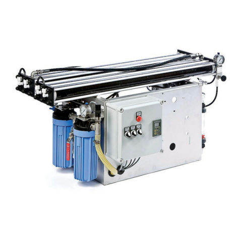
Enwa EnwaMatic EM BS 300 User manual

GENERIC MANUAL - FOR REFERENCE ONLY.
ALL BESPOKE UNITS WILL HAVE PROJECT SPECIFIC DETAILS

EnwaMatic® Bespoke BS 300
Contents
Declaration of conformity: 2
Pressure test certificate: 3
Contacts: 4
Installation notes: 5
Installation schematic: 6
Actuator switch positions: 7
EnwaMatic Operation: 8
Flow diagram: Service / Backwash: 9
Control panel operation: 11
Maintenance & Troubleshooting: 13
Pump data sheets 16
Wiring diagrams: 20

2


EnwaMatic® Bespoke BS 300
Installation Notes
Refer to installation schematic:
The unit should connect to two DN50 / 2” isolation valves on the main district heating scheme
(DHS).
Flow through the vessel is driven by a dedicated circulation pump: Grundfos CRI 20-1.
Inlet / outlet line size is DN50 / 2”. Mains water and drain is DN25 / 1”.
A boosted mains water supply is used to backwash the filter media. A DN25 / 1” isolating valve is
provided on the break tank inlet. This feeds a 570 litre insulated GRP break tank via a solenoid
valve (24 vdc, NC). This valve is linked to the control panel and programmed such that the valve
will only open during backwash and where the break tank is below a set level. Additional security
is provided by an additional float level switch.
The tank is fitted with a raised inlet chamber and weir to provide Fluid Category 5 backflow
prevention.
A submersible pump within the break tank provides sufficient flow and head to backwash the filter
at 85 l/min. The Lowara Genyo pump controller is energised during the backwash cycle only and
is activated by pressure drop as the valves move into backwash positions.
The unit drain (backwash outlet) should discharge to a suitable floor drain – ideally such that the
flow is visible to the operator. This drain will be tested to ensure it is capable of receiving flows up
to 85 l/min for 15 minutes. It is critical that this drain is not blocked or impaired in any way.
All pipework and components are stainless steel, with the exception of the solenoid valve (mains
water supply), which has a brass body.
Insulation:
The vessel has internal, 100mm insulation.
External pipework requires insulation by the installer post commissioning.
The main power supply required is 20 A, 230V, single phase. The schematic shows the 230V,
24 VDC and signal cabling.
All pumps are powered from the main control panel.
A local isolator switch on the incoming supply should be installed close to the installation.
5

A
D
C
B1B2
VESSELOUTLET
VESSELINLET
AIRVENT
STRAINER
P
BACKWASH
OUTLET
TODRAIN
GRUNDFOSCRI20-1
TOFLOOR
ORDRAIN
DN50
DN25
DN25
DN50
FLOW
INDICATOR
SAMPLE
VALVE
DHS
INLET
FLOWREG
BYPASS
MCW
REG
DHS
OUTLET
MCW
INLET
P
MANUALVALVE
MOTORISEDVALVE
PRESSUREGAUGE
WAFERNONRETURN
2"BSP-F
2"BSP-F
2"BSP-F
1"BSP-F
1"BSP-F
1/2"BSP-F
DN50
PLASTIC
SCREENED
OVERFLOW
DRAIN
DABPULSAR30/80
PUMP
CONTROLLER1"BSP-M
1"BSP-FMCWSUPPLY
DN25
SOLENOIDVALVE
20 A
230V
50HZ
BMS
24VDCACTUATOR
ANDSENSORCABLING
CONTROLPANEL
FC5BREAKTANK+
BOOSTERPUMPASSEMBLY
2"BSP-F
INSTALLATIONSCHEMATIC
BESPOKE BS 300
JT4.6.15
PIPEWORKBYINSTALLER
230VELECTRICALBYINSTALLER
6

EnwaMatic® Bespoke BS 300
Actuator switch positions
Actuator handles are mounted in line with the valve stem, such that a closed valve handle is
perpendicular to the pipe on which it is mounted.
The green mark indicates the required contact status (S1>S3) for a closed valve.
Actuators are set up by ENWA at commissioning.
STATUS
OFF
RUN
BACKWASH
ACTUATOR A
ACTUATOR B1/B2
ACTUATOR C
ACTUATOR D
7

EnwaMatic® Bespoke BS 300
Operation
The EnwaMatic® Bespoke BS 300 is a dedicated side stream filtration / water treatment unit for
the DHS.A small percentage of the main flow is diverted through the vessel, such that total
system volume is turned over 1 - 2 times per day.
Side-stream filtration to less than 5 microns.
Inhibition of corrosion – maintaining a dissolved iron level of < 1.0 mg/l.
Regulation of hardness and scaling through calcite / dolomite media filtration.
Removal of air through integral air separation device.
Environmental restriction of bacterial growth.
Normal operation:
During normal operation, water enters the top of the vessel, passing through specialist filter
media, reaction media and gravel base layers to a strainer on the bottom outlet. Debris is
progressively collected by the filter media as it passes through the bed.
The flow rate is 200 l/min. This equates to position 7- 8 on the sight flow indicator.
Flow rate through the unit can be observed on the sight flow indicator and adjusted using the flow
regulator valve on the central column (see mechanical schematic).
This is a fully automated backwash system, requiring no on-site operation or maintenance.
Isolation:
The unit should be isolated by:
Pressing ‘Off’ on the control panel PLC interface.
Closing the main system isolation valves.
Turn off control panel prior to undertaking any work on the equipment.
The unit can be isolated for several days without a deterioration in water quality. If prolonged
periods of isolation are required, please contact ENWA for advice.
Automated backwash:
Backwashing is set at the control panel for 2 week intervals as default. This will be reviewed at
commissioning and on follow-up visits. The actuator positions and direction of water flow during
service and backwash are shown in the enclosed drawing.
8

BESPOKEBS300
JT - 4.6.15
ACTUATOR POSITIONS
DIRECTION OF FLOW
SERVICEBACKWASH
9

The sequence is:
1) Circulation pump is switched off.
2) Unit isolation valves (Valves C & D) close. Green light on panel goes out.
3) Valve B1 and the additional drain isolation Valve B2 move to backwash positions.
4) Valve A moves to backwash position. (MCW isolation open). Orange light on panel.
5) Breaktank pump is activated and backwash commences. This lasts for 10 - 15 minutes.
6) Unit returns to service. Pump is switched on.
The additional isolation valves have been included to increase system security. The unit cannot
return to service if these valves are not closed.
Fluid Category 5 (FC5) break tank and booster pump:
EM BS 300 units require a higher flow rate than can normally be supplied directly by a mains
water connection. To accommodate this, and to meet Water Regulations concerning connection
to mains water, a break tank is employed.
The tank is filled by a servo type solenoid valve. This valve is normally closed, requiring a 24 vdc
supply from the control panel to open. This can only happen during backwash and when the tank
is below the solenoid activation level.
A submersible pump (DAB Pulsar 30/80) within the tank provides the required backwash flow rate
and is controlled by a pressure switch within the Lowara Genyo pump controller. This controller
is only energized during the backwash process.
A hall effect level sensor controls the solenoid operation and provides a high & low level alarm.
An additional float level switch provides a back-up high level alarm, which will shut down the
water supply.
Failure of the FC5 device to correctly operate for the required time period during the backwash
cycle will generate an alarm.
Status of the solenoid valve, level sensor and pump controller are displayed on the PLC.
Backwash Flow Rate:
The flow rate is set on the regulating valve adjacent to Valve A. ENWA will set this flow at
commissioning, with final adjustment on the follow-up visit, when the unit has been in service for
several weeks. The drain will be tested and confirmed capable of receiving this flow rate.
Circulation pump:
Refer to attached data sheets. This is a fixed speed pump, controlled via the control panel. Flow
through the unit is confirmed by a flow switch and will provide an alarm if no flow is registered
past a set delay period. Status of pump and flow switch are displayed on the PLC screen.
Manual over-ride:
It is possible to manually operate the valves, but this is not recommended for normal operation.
Valves are moved by depressing the black button on the orange Belimo casing and turning the
black handle on the actuator. The panel must be switched off to override the permanent 24 vdc
supply, designed to keep valves closed.
10

EnwaMatic® Bespoke BS 300
Control Panel Operation
Indicator lamps are provided for basic ‘Run’, ‘Backwash’ and ‘Fault’ status. These outputs are
linked to relays which provide volt free contacts for BMS connection.
PLC display (HMI):
Bespoke, project specific software is installed to control and monitor the installation.
The HMI has 5 direct switch inputs:
ON - returns panel to normal operation after alarms or manual shut-down.
OFF - provides manual shutdown, without loss of power.
Pumps are switched off.All valves are closed.
BACKWASH - allows user to initiate a complete automated backwash cycle.
ALARM RESET - investigate and reset alarms.
ESC - return from menus.
In standby mode the PLC will display the ENWA logo only. Touch the screen to access the main
HMI display. The various status indicators are shown above.
11

Alarm menu:
Pressing the HMI button ‘ALARM RESET’ allows any alarms generated to be investigated.
Pressing the magnifying glass icon on the screen will expand any alarm groups.
Pressing the ‘Reset’ screen button will clear the alarm – if the cause has been rectified or is
currently inactive. Unless the cause is immediately apparent and can be safely restored, please
contact ENWA for further assistance.
Pressing ‘ALARM RESET’ when no current alarms are present allows the alarm history to be
seen.
Alarm conditions:
Alarm ID:
Description:
Notes:
000
Alarm Valve A
Valve in wrong position for current status
001
Alarm Valve B
Valve in wrong position for current status
002
Alarm Valve C
Valve in wrong position for current status
003
Alarm Valve D
Valve in wrong position for current status
004
Alarm pump UPS
Pump not started in RUN status
006
Break tank low level
Tank level has remained low beyond pre-set
delay period.
017
Backwash duration alarm
Solenoid valve not activated for pre-set period
during backwashing.
023
Alarm Flow Switch Run
Lack of flow in RUN, with pre-set delay period
024
Alarm circuit breaker
Tripped MCB’s in control panel.
Additional options:
Pressing the control panel icon on the HMI screen accesses additional options.
Select ‘Backwash Log’ to view history. Press the ‘ESC’ button to return.
The ‘Test sequence’ is a partial test only and is not recommended post commissioning. Users
should press the ‘Backwash’ button to observe a complete test cycle.
‘Settings’ requires a password number and is not recommended for normal operation. ENWA
can advise if further access is required – for example to change backwash dates. In general, the
correct settings are established at commissioning and refined on the initial follow-up visits.
Further adjustment should not be required, and may affect correct operation of the unit and break
tank.
12

EnwaMatic® Bespoke BS 300
Maintenance & Troubleshooting
On site maintenance:
There is no on-site maintenance requirement.
It is recommended only that routine checks are made when visiting the plantroom:
•Visible flow: Position 7-8 on the sight flow indicator.
•Green light on control panel. PLC HMI display ‘On’, status ‘Run’.
Any problems should be reported to ENWA.
Warranty / Maintenance Agreement:
The standard warranty on all equipment supplied is 2 years from delivery:
The unit will operate under the additional water treatment warranty for 15 months post
commissioning.
Any problems should be reported directly to ENWA, who will advise or attend as required.
After this time, regular annual servicing by ENWA should be carried out to check all components,
clean the filter media, top up reaction media and analyse system water. This service extends the
warranty on the water treatment process for additional 12 month periods. Any problems arising
during these periods should again be reported to ENWA.
Spares:
There is no requirement to hold spares on site.
Side stream filtration / water treatment provides long term management of water quality. Units do
not need to operate continuously and can remain isolated for extended periods once established.
ENWA hold most components in stock for immediate dispatch. Grundfos pumps have a lead time
of 2 weeks.
13

Troubleshooting:
Lack of flow through unit:
Check panel status and program condition.
Check main system isolation valves.
Check circulation pump is running:
Check indicator status on PLC. Visually check rotation through top cover.
Check flow regulating valve is open.
Check actuator positions. (Refer to enclosed drawing)
Report to ENWA.
Control panel:
No green light:
Check power supply. Is the LCD display active?
Check panel status and program condition.
Unit may be in initial stage of backwash. Max duration 2 mins.
Check actuator positions.
Report to ENWA.
Orange light:
Unit is in backwash.
This should continue for 10-15 minutes maximum.
Red light:
Check alarm condition message. Reset if cause is clear and can be safely rectified.
Otherwise:
=> Isolate unit and report to ENWA
14

Backwash / Break Tank faults:
Lack of flow during backwash:
Check HMI display indicator status for breaktank pump controller.
Check mains water supply isolation valve.
Check position of regulating valve adjacent to Valve A.
Check actuator positions.
Visual check of break tank level and float switch position.
Check panel status: Incorrect valve positions, high / low tank level or solenoid inactivation will
generate an alarm after a pre-set period.
Report to ENWA.
Low break tank level alarm:
Break tanks may reach low level during normal operation. In this case the pump will switch off
and wait for the tank to refill, resetting automatically. If the tank level remains low beyond a pre-
set time period, an alarm will be generated.
Check mains water supply isolation valves.
Ensure position of regulating valve adjacent to Valve A is not altered.
Visual check of tank level and float switch position.
Report to ENWA.
Break tank duration alarm:
The PLC will check that the breaktank has been active for a minimum time period during
backwashing. If this has not been achieved by the end of the process, an alarm will be generated.
Check mains water supply isolation valves.
Check position of regulating valve adjacent to Valve A.
Check HMI display indicator status for breaktank pump controller and solenoid status.
Visual check of tank level and float switch position.
Report to ENWA.
15

Printed from Grundfos CAPS [2014.04.042]
Position Qty. Description
1CRI 20-1 A-FGJ-I-V-HQQV
Note! Product picture may differ from actual product
Product No.: 96500314
Vertical, multistage centrifugal pump with suction and discharge ports on same the level (in-line)
enabling installation in a horizontal one-pipe system. Pump materials in contact with the liquid are in
stainless steel. A cartridge shaft seal ensures high reliability, safe handling and easy service and
access. Power transmission is via a split coupling. Pipework connection is via combined DIN-ANSI-JIS
flanges.
The pump is fitted with a 1-phase, foot-mounted, fan-cooled asynchronous motor.
Liquid:
Pumped liquid: Water
Liquid temperature range: -20 .. 90 °C
Liquid temp: 20 °C
Density: 998.2 kg/m³
Technical:
Speed for pump data: 2789 rpm
Rated flow: 21 m³/h
Rated head: 9.5 m
Shaft seal: HQQV
Approvals on nameplate: CE,TR
Curve tolerance: ISO 9906:1999 Annex A
Materials:
Pump housing: Stainless steel
DIN W.-Nr. 1.4408
ASTM A 351 CF 8M
Impeller: Stainless steel
DIN W.-Nr. 1.4301
AISI 304
Installation:
Maximum ambient temperature: 40 °C
Max pressure at stated temp: 16 bar / 90 °C
16 bar / -20 °C
Flange standard: DIN
Pipe connection: DN 50
Pressure stage: PN 16
Flange size for motor: FT115
Electrical data:
Motor type: 90SB
IE Efficiency class: NA
Number of poles: 2
Rated power - P2: 1.1 kW
Power (P2) required by pump: 1.1 kW
Mains frequency: 50 Hz
Rated voltage: 1 x 220-230/240 V
Rated current: 7,40/6,70 A
Starting current: 390 %
16

Printed from Grundfos CAPS [2014.04.042]
H
[m]
0
1
2
3
4
5
6
7
8
9
10
11
12
13
14
15
Q [m³/h]0 5 10 15 20 25
eta
[%]
0
10
20
30
40
50
60
70
80
90
100
CRI 20-1, 1*230 V, 50Hz
Pumped liquid = Water
Liquid temperature = 20 °C
Density = 998.2 kg/m³
P
[kW]
0.0
0.2
0.4
0.6
0.8
1.0
1.2
1.4
NPSH
[m]
0
1
2
3
4
5
6
7
P1
P2
Description Value
General information:
Product name: CRI 20-1 A-FGJ-I-V-HQQV
Product No: 96500314
EAN number: 5700396199245
Price: On request
Technical:
Speed for pump data: 2789 rpm
Rated flow: 21 m³/h
Rated head: 9.5 m
Impellers: 01
Shaft seal: HQQV
Approvals on nameplate: CE,TR
Curve tolerance: ISO 9906:1999 Annex A
Stages: 2
Pump version: A
Model: A
Materials:
Pump housing: Stainless steel
DIN W.-Nr. 1.4408
ASTM A 351 CF 8M
Impeller: Stainless steel
DIN W.-Nr. 1.4301
AISI 304
Material code: I
Code for rubber: V
Installation:
Maximum ambient temperature: 40 °C
Max pressure at stated temp: 16 bar / 90 °C
16 bar / -20 °C
Flange standard: DIN
Connect code: FGJ
Pipe connection: DN 50
Pressure stage: PN 16
Flange size for motor: FT115
Liquid:
Pumped liquid: Water
Liquid temperature range: -20 .. 90 °C
Liquid temp: 20 °C
Density: 998.2 kg/m³
Electrical data:
Motor type: 90SB
IE Efficiency class: NA
Number of poles: 2
Rated power - P2: 1.1 kW
Power (P2) required by pump: 1.1 kW
Mains frequency: 50 Hz
Rated voltage: 1 x 220-230/240 V
Rated current: 7,40/6,70 A
Starting current: 390 %
Cos phi - power factor: 0,98/0,99
Rated speed: 2770 rpm
Motor efficiency at full load: 73-71 %
Enclosure class (IEC 34-5): 55 (Protect. water jets/dust)
Insulation class (IEC 85): F
Motor protec: PTO
Motor No: 85215705
Others:
Minimum efficiency index, MEI ≥: 0.7
Net weight: 47 kg
Gross weight: 60 kg
Shipping volume: 0.09 m3
17

Printed from Grundfos CAPS [2014.04.042]
Note! All units are in [mm] unless others are stated.
Disclaimer: This simplified dimensional drawing does not show all details.
96500314 CRI 20-1 50 Hz
178
139
130
200
300
65
120.5
215
248
G 1/2 G 1/2
G 1/2 18.5 x 21.8
281413
26
90
165
127
18

Printed from Grundfos CAPS [2014.04.042]
Note! All units are in [mm] unless others are stated.
96500314 CRI 20-1 50 Hz
19
Table of contents
Other Enwa Water Filtration System manuals
Popular Water Filtration System manuals by other brands

Wilkerson
Wilkerson M31 Installation & service instructions
My Water Filter
My Water Filter MWF BIG BLUE WHOLE HOUSE WATER FILTRATION... Installation Instructions and Product Care
Fernox
Fernox MKIII user guide
Propur
Propur PP500 - IC Installation and operating instructions
FM Mattsson
FM Mattsson Purify Flex Installation and maintenance instruction

Spectra
Spectra VENTURA TROPICAL 200 DELUXE owner's manual

