176
Assembly
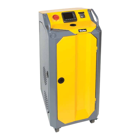
1) Install hoses to inlet and outlet
filters by threading the hose end
with the straight thread “o”-ring
seal fitting into the filter flange.
2) Connect the PVC tube wands to
the swivel fitting on the hose end.
Whenever servicing the PVC tube
wand do not overtorque the metal
fittings going into the PVC coupling.
Overtorque will result in cracking the
coupling. Generally, 1/4 turn beyond
handtight is sufficient.
Operating Instructions
1) Insert the inlet wand assembly
into the supply fluid receptacle
(drum/reservoir). The “RF”. filter
is the inlet filter.
2) Insert the outlet wand assembly
into the clean fluid receptacle
(drum/reservoir). The “CF” fIlter
is the outlet filter.
Caution:
Do not kink the hose assemblies,
this may result in excessive
vacuum or pressure at the pump.
3) Verify that the ON/OFF switch is
OFF and plug the cord into a 115V
10A grounded outlet (3 wire).
4) Turn switch to ON position and
check outlet wand for oil flow.
Allow 30 to 60 seconds for filters
to fill with oil. If repeated attempts
to obtain oil flow fail, check pump
inlet fittings for tightness, remove
inlet filter access cover and verify
the cover sealing “o”-ring is in
place. For very viscous fluids it
may be necessary to pour 1 or 2
quarts of fluid into the “RF” inlet
filter housing to prime pump
initially.
5) The condition of the filter
element should be monitored by
observing the cleanliness
indicator on the discharge
filter. When the Indicator is in the
CHANGE position, both inlet and
outlet filter elements MUST be
replaced to prevent fluid from
going into bypass in the filters.
6) The inlet filter Is provided with a
3PSI bypass spring, and prevents
the pump from cavitating If the
element is not changed. The outlet
filter is provided with a 25PSl
bypass spring to prevent excessive
pressure which may be harmful to
personnel or to the filter cart.
Warning:
The filter bypass spring acts as a
relief valve for the pump. Do not
restrict the discharge hose with
a shut-off valve which will defeat
the function of the bypass valve,
causing excessive pressure, which
may be harmful to personnel or to
the filter cart.
7) The cleanliness indicator works
on differential pressure and
will indicate the condition of the
element (CLEAN, CHANGE, or
BYPASS).
NOTE:
The filter cart must be in
operation for the indicator
to read properly.
Maintenance
Instructions
1) Turn switch to OFF position and
unplug cord from electrical outlet.
2) Remove tube wands from oil to
prevent siphoning.
3) Loosen hex head screws on
filter cover. Turn cover to clear
screws, remove cover.
4) Pull flow diverter assembly
from the filter head. Filter
element will follow the diverter.
a) Replace the cellulose,
synthetic or Microglass II
elements. Verify replacement.
b) Wire mesh elements can be
cleaned. Ultrasonic cleaners
provide best results.
5) Install element on flow diverter
and reinstall in filter housing.
Make sure diverter “o”-rings seat
properly into the head.
6) Check to be sure that the notch
on the flow diverter lines up with
the notch in the head.
7) Inspect the cover “o”-ring and
replace if necessary.
8) Replace cover and tighten hex
head screws until they are snug.
Do not over-torque these screws.
Do not interchange the inlet filter
cover with the outlet filter cover.
(The inlet filter has a “RF” prefix,
the outlet filter has a “CF” prefix).
Problem Cause Solution
Does not start. ON/OFF switch. Turn switch ON, replace switch if defective.
No electrical power. Plug in cart.
Defective motor. Replace.
Filter housing not filled with oil. Allow pump to run 30 to 60 seconds.
Suction leak. Check tightness of inlet fittings.
Check “o”-ring in inlet filter cover for nicks.
Kink or restriction in inlet hose.
Add 1 or 2 quarts of oil to inlet filter.
Defective pump. Replace pump.
Element dirty.
Replace or clean elements (both filters).
Oil extremely cold or viscous. Change element to coarser micron rating.
or BYPASS.
No outlet element. Install element.
40 micron element installed
Check cart model number to verify correct
in outlet filler. element. The inlet filter has a rating “RF”
prefix; the ouflet filter has a “CF” preflx.
Trouble Shooting
No oil flow or
erratic pump noise.
Indicator does not
seem to move.
Indicator reads
CHANGE
